To protect against shocks and shocks received by the wheels when driving on rough roads, the frame or load-bearing body suspended from the bridges with the help of elastic elements that form the suspension of the car.
The suspension consists of springs that soften the shocks received by the wheels, and shock absorbers that absorb body vibrations.
Distinguish between dependent and independent suspension.
A dependent suspension is a suspension in which the right and left wheel of one bridge are mounted on a rigid beam connected by springs to the frame.
Such a suspension is called independent, in which each of the wheels of the car is connected to the frame by levers and oscillates independently of the other.
Buses LiAZ-677 and Ikarus-260 are equipped with spring-pneumatic dependent suspension.
The elastic element of the suspension are two-section pneumatic cylinders. For fixing the front and rear axles the same scheme of the guiding device was used, consisting of two semi-elliptical springs, which perceive reactions from traction and braking torques.
The front spring consists of leaf springs assembled in a package with clamps and tie bolts. There are two root sheets, the ends of the sheets are bent. Stamped cups are riveted to the bent ends. The springs, together with the pillows in a straightened state, are installed in brackets that are welded to the base of the bus. The lower part of the brackets is closed with covers, which are fastened with bolts. The middle part of the spring is rigidly attached to the axle beam with bolts. For correct installation The front spring uses a wedge-shaped gasket.
rear spring differs from the front in that the number of sheets is reduced. To limit travel front axle up, buffers are installed on it, to limit the downward travel, limit the rebound, which is a cable loop.
Each air spring is equipped with one air vibration damper, which helps the shock absorbers dampen the vibrations of the springs.
The principle of operation of the air damper is that during the rebound stroke, air flows from the additional volume into the elastic element through the throttle hole, and during the compression stroke, the air freely flows into the additional volume.
A two-section air spring balloon consists of two to four layers of rubberized cord fabric, an inner rubber layer that ensures the tightness of the sheath and protection of the cord from oil and moisture, and an outer layer that protects the cord from mechanical damage and atmospheric influences.
Cord threads are made of nylon or kapron. The cylinder shell at the top and bottom has boards with steel rings and cords wrapped around them. The sealing of the cylinder is ensured by pressing rings. The profile of the clamping ring coincides with the profile of the bead shell, which ensures sealing over the entire inner surface of the ring.
The pressure ring is attached to the top and bottom flanges with 12 bolts. A tightening ring is installed between the sections of the balloon.
The body position regulator serves to automatically maintain a constant height of the bus body above the road at various loads.
In system air suspension three such regulators are installed: one in the front suspension and two in the rear. The regulator is attached to the bus body, and its lever is connected to the front or rear axles through a system of rods.
In the regulator housing there is a drive shaft, a rod, inlet valve first stage, second stage inlet valve with first stage jet, check valve.
From above, the body is closed with a stopper, in which the jet of the second stage is machined, and from below it is closed with a filter.
The shaft rotates in a bronze bushing, the rotation of the shaft is limited by a lock.
With an increase in the static load on the pneumatic peccora, the distance between the body and the wheel axle decreases, while the regulator lever and the shaft turn clockwise. An eccentric cam lifts the stem and the stem opens the first stage valve. Compressed air through the jet of the second stage "squeezing out the check valve, enters the jet of the first stage, then into the cavity of the regulator, and from there into the air springs, restoring its original height. When the lever returns to its original position, the air inlet will stop.
With a heavy load, when the end of the lever moves upwards by more than 30 mm, the first stage inlet valve opens the second stage valve with its end and accelerated compressed air is supplied through the second stage jet with a diameter of 1.5 mm.
When the load on the air springs decreases, the distance between the body and the axle of the wheels increases, the drive lever moves and the shaft turns counterclockwise. The stem moves down, its end moves away from the valve and the regulator cavity through the hollow stem and the filter is connected to the atmosphere. Before the Neutral position lever is engaged, the air is vented to the atmosphere.
To prevent air leakage at the joints of parts, the stem, shaft and plug are sealed with rubber rings.
A similar suspension is used on the Ikarus-260 bus, the difference is that the rear eye of the spring is connected to the base through an earring.
On the LAZ-695N bus, semi-elliptical steel springs work in conjunction with corrective springs of variable stiffness.
Long leaf springs with a small number of leaves provide soft suspension under light loads. As the load increases, the springs increase in stiffness.
The front suspension has hydraulic shock absorbers. Each spring has two main sheets, the ends of the sheets are bent to the ends of the springs, stamped cups are riveted and rubber cushions are put on. In the unloaded state, the spring is inserted into the brackets and secured with covers. The front end of the spring with closed cups is fixed in the rubber cushion, and the rear end has free longitudinal movement in the cushion. The springs are attached to the beams with stepladders through spacers. An overlay with an eyelet is installed on the beam, to which two plates of an equalizing earring are hingedly connected in the form of a triangle with its apex down. The upper corners of the equalizing earring are pivotally connected to the corrective springs.
The other ends of the springs on the axles are pivotally attached to the longitudinal beams of the base. All swivel joints are made on rubber bushings, consisting of two halves. The bushings are clamped with fingers with a nut and should not turn.
The use of rubber bushings and cushions eliminates hard contact with the body, reduces noise and vibration.
Rubber cushions prevent the springs from hitting the longitudinal beams of the base.
The suspension of the PAZ-672 bus is made on longitudinal semi-elliptical springs. Telescopic hydraulic shock absorbers are installed in the front and rear suspensions. The springs are attached to the base on rubber pads.
Cups are attached to the ends of two root sheets, into which rubber cushions are inserted: large cushions - into the cups of the top sheet, small ones - into the cups of the bottom sheet. The cushions with the ends of the springs are clamped by covers in the brackets of the base of the bus. A shock absorber is attached to the base bracket.
In the front brackets of the springs, additional thrust pads are installed in special sockets, which perceive the forces directed along the bus and prevent the longitudinal movement of the spring. Rear suspension has additional springs, which are fixed together with the main spring by ladders, and their ends are against the shelves of the support brackets.
In the unloaded state of the bus, the additional springs do not work, and when loaded, resting their ends against the brackets, they carry the load along with the main springs.
If the spring bushings are metal, then the spring fingers are lubricated with grease.
Rubber and nylon bushings are not lubricated. To reduce friction, the surface of the leaf springs is lubricated with graphite grease. The entire package of leaf springs is pulled together by a coupling bolt. A buffer is installed to limit the deflection of the spring.
Shock absorbers serve to dampen vibrations of the springs. All the buses under study are equipped with double-acting telescopic shock absorbers, which provide damping of vibrations when the wheel moves up and down relative to the vehicle's carrier system.
The shock absorber MAZ-500, unified for many brands of cars, consists of a casing to which the upper lug is welded, and a body to which the lower lug is welded.
Inside the housing is a working cylinder filled with shock absorber fluid. A piston is placed in the cylinder above the liquid, which is rigidly connected through the rod to the shock absorber lug. The shock absorber with its eyes is attached between the body and the spring.
Two valves are pressed into the bottom of the cylinder. Compression valve with base and spring and inlet poppet valve with spring and orifice.
The piston is sealed in the cylinder with rings. The piston is made in two rows of through holes, evenly spaced along the circles of different diameters. The through holes are closed from above with a flat plate loaded with a conical spring. When assembled, this assembly forms a bypass valve.
The through holes of the piston are blocked by a conical valve pressed from below by a spring and a nut. Together, this assembly forms a recoil valve.
The top of the cylinder is closed with a lid, which is also a rod guide. The sealing of the stem in the cover is provided by a rubber ring and gland. To prevent dust from entering the stuffing box, a felt seal is installed above it, and an stuffing box seal of the shock absorber body is installed between the stuffing box body and the shock absorber body, which is fastened with a nut with a key hole.
To prevent liquid pressure on the stuffing box seal leaking between the stem and the cover, a hole is made in the cylinder through which the liquid flows.
The work of the shock absorber is as follows. When hitting an uneven road, the distance between the axle and the frame decreases. The piston goes down, the liquid from under the piston is squeezed out into the above piston space A through the piston hole and at the same time, exerting pressure on the compression valve, penetrates into the space B between the cylinder and the housing. As the distance between the suspension and the body increases, the fluid flows back through the valve hole and the valve hole. The resistance of the fluid to flow through the calibrated holes contributes to the damping of the oscillation.
Combined pendants LIAZ
The bus suspension is the link between the body and the wheels. On buses LiAZ-677M, -677G, LAZ-4202, -42021, etc., pneumatic spring dependent suspensions. They differ mainly from the suspension of cars by the presence of an elastic element through which, through the springs, the forces acting on the wheels are transmitted to the body. The pneumatic elements included in the suspension, together with the hydraulic shock absorbers of the type described above, reduce body vibrations, provide good stability and smooth running of the bus, which is necessary for the comfort of passengers.
The air spring suspension has semi-elliptical springs as elastic elements, which perceive reactions from both traction braking torques and lateral forces, and pneumatic two-section rubber-cord shells of standard size 300-200, model I-02, called pneumocylinders. On each side, the suspension has a main spring from a ZIL-130 car, an air bellow and a telescopic shock absorber from a MAZ-500 car.
Device and work. The main element of the air suspension is an adjustable air spring. The spread of air springs on cars is associated with their advantage over other elastic elements: the ease of adjusting the main indicators and changing the characteristics of the suspension. The air suspension is adjusted by supplying or discharging liquid or gas to the air springs. As a result of such regulation, it is easy to change the position of the body and wheels, the stiffness of the suspension and the natural frequency of the body. The load capacity of the air spring is provided by the pressure of compressed air (or gas), and the stiffness is provided by the volume in which this air is located. The change in carrying capacity when loading or unloading the car is compensated by an increase or decrease in the pressure of compressed air in the pneumatic spring. Pneumatic springs change stiffness depending on the vibration frequency of the body and wheels. With an increase in the speed of movement, the suspension becomes stiffer.
The designs of adjustable air springs are very diverse, work on their improvement is ongoing, new schemes and design solutions are constantly being proposed. However, all types of adjustable air springs can be divided into two main types (Fig. 4.21): telescopic piston springs and air springs made on the basis of rubber-cord shells (RKO).
The main parts of the piston spring (Fig. 4.21, a) are the piston /, the working cylinder 2, the steel sphere 3, separated by a flexible rubber diaphragm 4. working body- gas (usually nitrogen) is in the steel sphere 3. Compressed gas is filled into the spring through valve 5. The air spring is controlled by supplying fluid 7 to the cylinder with the piston. At the exit from the working cylinder into the sphere, the liquid passes through the throttle 6 - a device that acts as a hydraulic shock absorber. Thus, elastic element combined in one design with a quenching device.
Figure 4.21, b shows a diagram of an adjustable air spring with RKO. On the body of the hydraulic shock absorber 11, an RKO 12 is fixed, made in the form of a sleeve, which, when the suspension is moved, rolls over the body 11. The design of the sleeve with a cord frame 9, an outer protective 8 and sealing 10 rubber layers resembles a tire device. The working volume of compressed air is enclosed between the RKO and the cup 13. An additional volume 15 can be connected to the air spring. Compressed air is supplied to the air spring through fitting 14. The method of changing the pressure of compressed air (or gas) affects the characteristics of the air spring. With a stationary piston, the liquid supply (Fig. 4.21, a) increases the gas pressure as a result of a decrease in its volume, while its mass remains unchanged. If compressed air is supplied to the air spring (Fig. 4.21, b), then the pressure will increase due to an increase in the mass of air, and the volume it occupies will remain the same. In the first case, the frequency of the body's natural vibrations increases and the smoothness of the car's running worsens, in the second, the frequency of the natural vibrations of the body and the smoothness of the ride are preserved.
The ability of air springs with RKO to keep the car running smoothly, regardless of whether it is loaded or empty, is of great importance. Such air springs are used on buses and trucks, the carrying capacity of which varies significantly. Piston air springs are used on passenger cars, the change in carrying capacity of which is small. It is possible to improve the characteristic of a piston air spring when the compressed gas pressure changes by connecting additional pneumatic elastic elements.
Adjustable air springs allow you to increase the stiffness of the suspension when the car is moving with high speed on a good road or low speed off-road. To change the stiffness of the air springs, an additional volume for compressed air is used (Fig. 4.21, b) or an additional pneumatic elastic element (Fig. 4.22).
If an additional volume 15 is connected to the air spring with RKO (see Fig. 4.21, b), then its rigidity will decrease, the suspension will be soft. When the additional volume is turned off, the suspension will be stiffened.
Figure 4.22 shows a scheme with three elastic elements used on Citroen cars (France). The main elastic elements 1 and 3 are installed in the wheel suspension guides. Additional elastic element 2 is connected by pipelines to the main ones. All three elements have the same pressures and volumes of compressed gas and do not differ from each other in design.
During the control of the suspension with the help of valves 4, it is possible to turn on and off the additional elastic element 2. When it is turned on, the stiffness of the suspension is significantly reduced, when it is turned off, it increases. In addition to regulating the position of the body and wheels, the suspension has two more modes of operation: “soft” with additional element and "hard" without it.
Figure 4.23 shows the design of a piston air spring. Compressed gas (nitrogen) is enclosed in a metal sphere, consisting of two parts - upper 5 and lower 8. The load on the gas is transferred by liquid through the separating diaphragm 7. When the spring is operating, the liquid displaced by piston 3 passes through the built-in shock absorber 9. It is connected to the car wheel rod /, which transmits forces to the piston through the thrust heel 11. Seals 12 are installed between the cylinder 10 and the piston 3. From below, the air spring is isolated from environment housing 13 with a device for draining fluid 2. When adjusting the spring, fluid is supplied through hole 4. The spring is filled with compressed gas using filling valve 6.
Figure 4.24 shows a diagram of an adjustable air suspension. The position of the body is controlled using a regulator, the drive 3 of which is connected to the suspension guide. In a piston spring, gas 4 and liquid 5 are separated by a diaphragm. The regulator has channels for supplying / and draining 2 liquids. A shock absorber is placed in the spring 6. When the load increases, the body lowers, and the regulator supplies fluid to the air spring cylinder, restoring the position of the body. With a decrease in vehicle load, the regulator ensures that fluid is drained from the air spring to maintain the position of the body.
The first passenger car mass production on air suspension was famous french car"Citroen DS-19", the serial production of which began in 1955. Adjustable piston air springs were installed on all wheels of the car. Citroen cars with such air springs are successfully produced at the present time. Pneumatic springs with RKO first appeared on mass-produced passenger cars in 1957 in the USA. It was expensive car Cadillac Eldorado. In the air suspension of the car, diaphragm-type RKOs were used. The same RKOs were installed on stock car Mercedes-Benz 300 CE produced in 1961. It turned out to be one of latest cars with this type of air suspension. Attempts to use the RKO of the diaphragm type have not gained distribution in passenger cars.
in the USSR in the early 1950s. intensive development of pneumatic suspensions for buses and trucks was carried out. At the All-Union Conference on the Problems of Air Suspension, prototypes of trucks and buses with air springs based on RKO were presented. Later started mass production buses with air suspension at the Lvov and Likinsky bus and trolleybus named after Uritsky (ZiU) plants. Experienced car"Moskvich" with air suspension was made in the late 60s. at the Izhevsk Automobile Plant.
Interest in air suspensions with RCS for passenger cars resurfaced when the possibility of using sleeve-type RCS in combination with electronic control systems became clear. Currently, controlled air suspensions are used by many leading automotive plants in Europe, the USA and
In vehicles with air suspension, the axle load is distributed between pneumatic cylinders filled with compressed air. Air suspension has been in use for over 40 years and has been shown to provide maximum comfort and smooth running vehicle compared to other types of pendants.
About the properties of air suspension
Modern pneumatic cylinders are produced using the same technology as tires for wheels - reinforcing cords are stretched in rubber, significantly reinforcing the structure. As a result, the service life of pneumatic cylinders is quite impressive and amounts to several years, subject to installation requirements.
In addition, the air suspension has some additional properties to achieve the most comfortable ride of the vehicle. Firstly, the system automatically regulates the air pressure in the pneumatic cylinders to maintain the specified ground clearance of the vehicle while driving, regardless of its load. Thereby possible move suspension is not reduced and remains maximum regardless of vehicle loading.
With increased loading in pneumatic cylinders, high blood pressure, as a result, the suspension becomes rigid and the stability of the vehicle is ensured. When the vehicle is lightly loaded, the pressure in the pneumatic cylinders decreases, the suspension becomes softer, while the stability of the vehicle remains unchanged.
Since each wheel is equipped with a separate air cylinder, the air suspension is independent. Automatic control pressure in the cylinders is carried out by an electronic module specially designed for autonomous use in vehicles.
Electronic system continuously monitors the “height” of the suspension and, in case of its decrease, pressurizes the cylinders with the help of a compressor. The compressor automatically turns off when the desired height of the car body is reached. If the suspension height is higher than the set value, the pressure is automatically released by the vent valve until the set values are reached. All air suspension components are powered by a 12-volt battery vehicle.
General information and history
Air suspension, promoted by Lincoln in 1984 in an advertisement for some car models, was first introduced in 1909 by the Cowey Motor Works of Great Britain. The suspension did not receive recognition in those days, because it was unstable due to constant leaks.

Picture 1. american car Stout-Scarab with air suspension, released in 1933.
The first truly working air suspension was developed by Firestone in 1933 for the experimental car Stout-Scarab (Figure 1). This car with rear location The engine was equipped with 4 rubber pneumatic shock absorbers installed instead of standard springs.
The air pressure in the shock absorbers was maintained by 4 small compressors connected to each air cylinder. The design cost a lot of money in those days, however, even today, air suspension is quite an expensive pleasure.

Figure 2. Suspension Locations: 1-Right Shock, 2-Compressor, 3-Left Shock, 4-Rear Height Sensor, 5-Suspension Switch, 6-Air Line, 7-Air Tanks, 8-Lower Suspension Arm, 9- Front height sensor.
In air suspension, the vehicle body is supported on wheels by pneumatic cylinders instead of springs, leaf springs, etc. Suspension types with steel shock absorbers or air-filled torsion bars are not classified as air suspension.
There are combined types of vehicle suspension, which use both air springs and metal springs. Most often, air suspension is installed on the rear axle of the car.
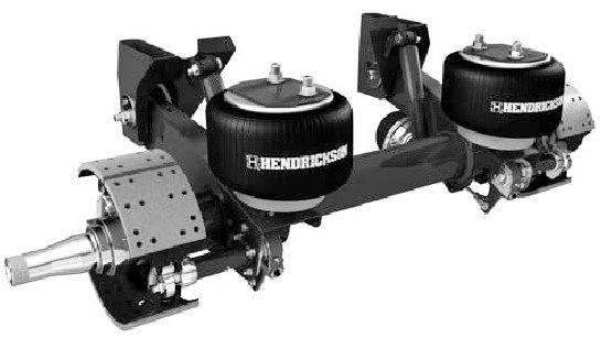
Figure 3. Air suspension of complex design.
In most cases, the main purpose of the air suspension is to level the vehicle. Typically, air suspension is part of the vehicle's air system. Most (but not all) air suspension vehicles are also equipped with air brakes and other pneumatic equipment. Problems with this equipment may affect the performance of the air suspension.
It is important to understand that when designing a vehicle's pneumatic systems, the manufacturer must adhere to established regulations to prevent equipment failure.
Especially it concerns brake system- its performance should be a priority in the general pneumatic system of the car.
Air suspension components
The pneumatic system consists of 3 main elements - a source of compressed air, pneumatic cylinders and valves (see Figure 4). There are many varieties of these components and methods of their application. IN this review we will consider only a few different implementations.

Figure 4. Elements of the pneumatic system and pneumatic cylinder.
Pneumatic cylinder
The pneumatic cylinder is a rubber cylinder ( air cushion) filled with compressed air (Figure 4). The plastic stem on the lower arm moves up and down with the arm. As a result, the resistance of the compressed air in the cylinder dampens the vibrations of the lever.
When the vehicle load changes, the valve at the top of the air spring opens to build up or relieve pressure. A pneumatic line is connected to the valve, through which compressed air is supplied, which is pumped by the compressor to maintain the set pressure.

Figure 5. Pneumatic cylinder operation.
Pneumatic shock absorbers
Pneumatic shock absorbers are equipped with a rubber boot placed on the shock absorber (Figure 6). Thanks to this constructive solution a sealed air chamber filled with compressed air is formed. Compressed air increases the load capacity of the vehicle without its subsidence.

Figure 6. Pneumatic shock absorber.
Some pneumatic shock absorbers are filled with compressed air through special valves on the service stations. After the cargo is transported, the pressure is released to ensure normal clearance.

Figure 7. Diagram of the pneumatic system.
Benefits of air suspension
- Provides a constant clearance for any vehicle load;
- The ability to adjust the stiffness of the suspension;
- Constant natural frequency, respectively better handling at any load of the vehicle;
- Reduces driver and passenger fatigue.
Applications for air suspension
- Hot rods, cargo and cars, motorcycles;
- luxury vehicles;
- Lifting mechanisms in cargo vehicles (Figure 8);
- Buses with electronically controlled suspension (low-floor, tilting buses).

Figure 8 lifting mechanism with air balloons.
Air suspension with electronic control
When installing air suspension with electronic control the standard springs on all wheels are replaced with pneumatic cylinders (Figure 9). The electronic system controls the compression ratio in the cylinders and automatically adjusts the clearance and level of the vehicle relative to the roadway.
On the rear axle of the car, pneumatic cylinders are mounted in front of the axle on lower arms, on the front axle - are part of suspension struts front wheels. These struts (Figure 10) are installed between the car body and the steering knuckle.

Figure 9. Pneumatic system with air bellows installed on all wheels of the vehicle.
An electric compressor pressurizes the air in the system (Figure 9). A dehumidifier attached to the compressor removes the moisture contained in the air as water can damage the system. Further, the air enters the pneumatic lines going from the compressor to each of the pneumatic cylinders.
A solenoid valve is placed in front of each cylinder, which opens or closes to pressurize or depressurize the cylinder. The control module controls the operation of the compressor and solenoid valves.

Figure 10. Construction of an air strut equipped with an air spring, a solenoid valve and a built-in height sensor.
The system uses 3 height sensors: at the front of the air struts (Figure 10) and at the right rear of the air spring (Figure 6). When the body is loaded, the sensor is triggered, the signal from which is transmitted to the control module. The control module turns on the compressor and opens the solenoid valves on the air springs.
As a result, pressure is built up in the cylinders, they are stretched, and the body rises to a predetermined height relative to the roadway. The control module then switches off the compressor and closes the solenoid valves.
After unloading the vehicle, the clearance increases, as a result of which the height of the body relative to the roadway exceeds the specified values, and the height sensors transmit a corresponding signal to the control module.
The control module opens the solenoid valves to bleed air, the body lowers to a predetermined height, after which the control module closes the solenoid valves.
Automatic level control
Many vehicles are equipped with automatic or electronic level control (Figure 11). The two rear air springs are connected via pneumatic lines to the compressor. At least one of the shock absorbers has a height sensor installed (Figures 6 and 11). When the load is on the rear or front of the car, the sensors are transmitted to electronic module Altitude change signal control.
As a result, the control module turns on the compressor to pressurize the air springs. If the vehicle is unloading, the control module opens the valves to bleed air from the shock absorbers.

Figure 11. Automatic leveling system. The height sensor in the shock absorber signals the need to turn the compressor on and off.
Electronic control module
(See Figure 12)
- It is the "brain" of the electronically adjustable suspension;
- Has a compact design;
- Handles driver requests from the control panel;
- Governs solenoid valves to ensure a given clearance;
- Continuously monitors system status.
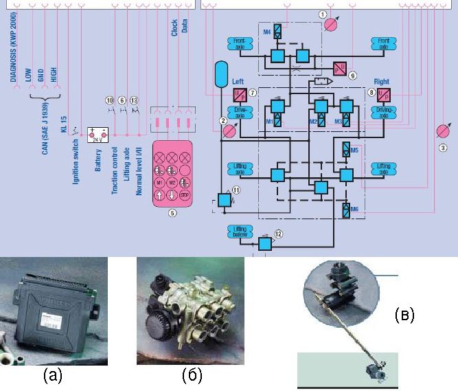
Figure 12. Sample diagram and appearance electronic block control, the appearance of the valve block and height sensor.
Solenoid valve block
(Figure 12, b)
- Modular system minimizing the number of pneumatic pipelines;
- Reduces response time to seconds;
- Fewer equipment reduces the chance of leaks;
- Minimum space requirement for installation.
Height sensors
(Figure 12, c)
- Three sensor system;
- Provide registration of vehicle clearance at any load.
Scope of electronically controlled air suspension
Thanks to the modular design pneumatic system with electronic control is used:
- In trucks with pneumatic elements on the rear axle, with pneumatic elements on the rear axle and in lifting device, with pneumatic elements on the rear and front axles, with pneumatic elements on the rear and front axles and in the lifting device;
- In buses equipped with air suspension;
- In trailers equipped with air suspension;
- In light commercial vehicles and passenger cars.
Electronically controlled air suspension can be optionally equipped with remote control management and has the following advantages:
- Ensures the parallelism of the vehicle body relative to the roadway, even with uneven loading;
- Provides a constant level of the loading platform without the need for manual adjustments;
- Keeps the system running exchange rate stability in accordance with existing European requirements. This system can also be used to optimally distribute the load on the vehicle axles;
- Rapid increase and decrease in clearance;
- Low air consumption, since short dynamic loads on pneumatic cylinders do not entail starting the compressor;
- Compatibility with low-floor buses;
- Load indication;
- Long service life;
- A little free space is required to install the system and piping.
Application of Electronic Air Suspension in Commercial Vehicles
Let's talk about the application of such a system in large commercial vehicles such as buses.
Clearance control and body alignment relative to the roadway
Height sensors continuously measure the distance between the axle and the vehicle body, transmitting the obtained values to the electronic control module. As the vehicle load increases or decreases, the measured height changes.
These changes are registered by the control unit, which automatically maintains the set height with the help of valves, which has a positive effect on driving performance, comfort and handling of the vehicle.
After stopping the bus at the command of the driver, it can be raised or lowered for the convenience of boarding / disembarking passengers (Figure 13).

Figure 13. Modern bus leaned over at a stop for boarding / disembarking passengers.
Riding with high and low ground clearance
The air suspension allows the driver to increase / decrease ground clearance in difficult places (for example, when moving through railway), when driving on sloping roads (drives, entrances to overpasses, etc.) and when driving through road sections limited in height.
The increased ground clearance prevents the bottom of the car from catching on the road, while the reduced clearance prevents the roof from clinging to overhanging obstacles. The system usually implements a height limit to prevent overpressurization of the air cylinders when the ground clearance is increased.

Figure 14. Driving with low and high ground clearance.
Locking doors and gearbox
Passenger safety regulations require that the parking brake be applied, the doors closed, and the gear engaged in neutral before lowering the vehicle when parked.
Easy Diagnosis
There are two user-friendly types of diagnostics:
- Standard blink codes;
- PC diagnostics.
Application in trucks
Air suspension in large trucks performs two important tasks: it raises and lowers the chassis for hitching a trailer and helps stabilize vehicles with a high center of gravity on the road.
Major truck manufacturers such as Ashok Leyland and others have developed electronically controlled air suspension for their heavy vehicles the next generation, fully meeting all established requirements (1360 requirements). In addition, the installed systems must ensure the comfort and safety of drivers of 40-ton trucks.
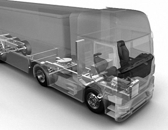
Figure 15. Electronically controlled air suspension components in heavy duty vehicles.
Advantages of electronically controlled air suspension:
- Better ride and handling of the vehicle;
- Reduced transmission vibration and wear;
- Easy embarkation / disembarkation of passengers;
- Possibility of vehicle passage to previously inaccessible areas;
- Reduced air consumption;
- Alignment of the vehicle body even with uneven loading;
- High adaptability of the vehicle to changing road conditions.
Suspension in low-floor buses

Figure 16. City bus - dimensions, appearance, design of steps.

Figure 17. Bus frame.

Figure 18. Front and rear suspension. Before - spring suspension with rubber finish. Rear axle- air suspension.
Suspension Specifications
| Number | Description | Meaning | 5460 | 10200 |
| 3 | Stiffness of front springs, kg/mm | 34.7 |
| 4 | Rigidity of back pneumocylinders, kg/mm | 15.42 |
| 5 | Natural swing frequency of the front suspension, Hz | 1.7 |
| 6 | Natural swing frequency of the rear suspension, Hz | 1.3 |
| 7 | Lateral stiffness of the front suspension (spring), Nm/g | 1960 |
| 8 | Lateral stiffness rear air suspension, Nm/g | 7415.6 |
| 9 | Lateral stiffness rear stabilizer suspension, Nm/g | 5554.7 |
| 10 | Lateral stiffness of the rear suspension, Nm/g | 12970.3 |
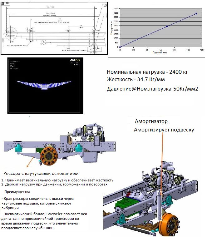
Figure 19. Front suspension.

Figure 20. Rear suspension.
Rear Air Suspension - Kinematic Analysis

Figure 21. Kinematic analysis.

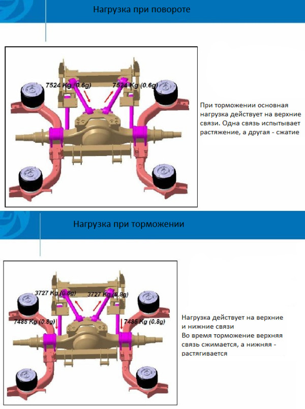

Figure 24. Rear suspension stiffness graph.

Figure 25. Final elemental analysis of the rear suspension brackets.

Figure 26. Rear Suspension - Axle Bracket Analysis.

Figure 27. Bench tests.
Bench tests of the air suspension were carried out for the following cases:
Conclusion
As a result of tests carried out in laboratory conditions, the advantages of electronically controlled air suspension over other standard types of suspensions have been confirmed:
- V this type suspension implemented the ability to adjust the clearance depending on road conditions;
- air suspension significantly increases the comfort of the vehicle and allows you to increase the ground clearance on difficult road sections and reduce it when driving on a freeway;
- the “tilt” function makes it easier for elderly passengers and people with disabilities to get into the vehicle;
- improves the course, stability and controllability of the vehicle;
- vibrations are reduced and transmission wear is reduced;
- it becomes possible to drive a vehicle on previously inaccessible sections of roads;
- electronically controlled system is characterized by reduced air consumption;
- the alignment of the vehicle is ensured even with uneven loading;
- the vehicle becomes more adaptable to changing road conditions.