Anti-lock braking system (ABS) - consists of sensors for the wheels, an acquired data processing unit, also contains modulators and electronic valves. The task of the sensors is to monitor the rotation of the wheels, their speed, they immediately send the acquired data to the data processing unit. The unit processes them and, based on the results, makes decisions whether to open or close the electric valves using modulators. Electric valves, in turn, are located directly in the brake system and keep the level and pressure of the brake water under control.
The ABS system is installed on all modern
cars, well, it was previously installed, except for Russian cars.
Every motorist knows that this system is very helpful when skidding to keep the car,
but it is necessary to frequently inspect the ABS for performance and good condition.
Fault definition
There is a crackling sound when you press the brake, but this is normal.
work of modulators. But a particularly strong crack indicates a breakdown, with all this if
on dashboard blazing light bulb abs, then you can safely engage in repairs;
In the event of a breakdown, the light bulb glows when the ignition is turned on, and when
the engine starts, the light goes out;
If the ABS light flashes while the engine is running, it means
there is also a breakdown in the system.
If you find the main malfunctions of ABS, then they will be
four:
When starting ABS, it gives a self-test error, then
the system is completely shut down. The problem may be in the breaks on the sensors or in
data processing unit. Sensors may not read angular velocities;
2nd moment, this is when the start of ABS and testing passes
Fine. But later the system still turns off. Most likely, this is a break in
wires, the contacts could boil and oxidize, or simply weakly
contact. A break in the ground or power wire may occur, the wire may
burn out due to short circuit;
What happens is that Abs starts up, passes the test and finds
error and without turning off, continues to work. The reason is most likely one
broken sensor. But also sensors can create a problem in a different pattern.
tread and submit different data, or the wheels are inflated differently, this
can also be awkward. One way or another, the sensor reads the speed and angle of inclination
rubber, wear, tread and tire pressure play an important role;
Constant operation of ABS when the system does not turn off at all.
IN this case it is necessary to find the cause in the wires, in the middle of them there will be a break near
sensor. Also, a broken hub (wheel bearing) can become a prerequisite,
damage to the rotary comb and free play.
Troubleshooting
Do a series of exploratory checks:
check the condition of your own tires for wear;
determine the pressure in the wheels and balance it;
inspect the wheel bearings for free play;
check the rotor brushes (combs), they should not be
broken or very dirty.
The comb can be simply cleaned in case of contamination, washed
her brush with kerosene. There may be problems with the availability of cleaning, for this
from time to time it is necessary to remove the wheel, but in general it is not difficult to do this on a lift or pit.
If part of the comb is broken, chipped, then it will help
just a change.
Wires require painstaking checking for their
integrity, it is also worth checking the contacts.
Check the condition of the sensors. If the above methods
they won’t help you, then the problem, most likely, lies in the electronics, in the block
data processing. But, usually, they fail first and
parts wear out. The best way to determine would be to get
error code. But there is a small problem here, not all blocks have memory, and the code
errors may not be saved, so you will have to diagnose in working condition.
How to Diagnose Abs
Data processing units are frisky and unhurried, in terms of
code exchange. If it's a frisky block, then there are adapters for it for
diagnostics.
frisky code
Each block has a connector for connection and diagnostics,
when the ignition fires, data counting starts. Then we find the code
error and compare it with the data in the error catalog, then read the description
difficulties. From time to time there are such cunning blocks that cannot even be read
give, but usually, and this sore has a description in the catalogs. The problem may
dare to open the block and connect to the controller board via a soldered
adapter.
Slow Code
Such blocks have special connectors, such a connector
marked as L-Line. The best is to purchase a special adapter
for slow codes. Such an adapter has an LED, according to a certain blinking and
number of flashes, you can read the error code according to the manual.
It is read quite easily, the 1st signal is 0, the duration
signal for about 3 seconds, and then there are flashes of 1 second, here in these
flashes and there is an error code. Usually, such a code consists of 4 flashes,
these flashes are separated from each other by a pause of three seconds. Those. if you saw
three flashes and a pause, this is read as the number 3, respectively, if 5 flashes and
pause, then this is the number 5, etc. Now, when there will be four such series with
pause, a 0 signal will be received, and record the acquired flash results, and you
get a digital error code like 3524.
If you have read and wish to continue counting new codes, then you need to close
connected wires to ground and chip, in
the moment when the 0 signal occurs.
Interpretations of errors can be found in the VORM catalog, however, it is on
British, although techno information is easy to translate. There are also on
Russian catalog VAG, but there is not all information about errors.
Controllers do not distinguish between errors, and give a grand total, i.e.
if one wheel gives 3 errors, and the 2nd one, then 2 will be processed
errors, but not 4.
How to test abs sensors
Normal - this is a car service, but for lovers of needlework
useful:
pins for repair;
heat shrink tape.
soldering iron;
The wheels must be released, i.e. raise. See in
operation manual and do everything as it is written there, and remove the cases
blocks.
Then the pins must be connected to the sensors, to the connectors and
measure the resistance with a tester. A typical sensor will output less than 1 ohm, but you
should be driven by your annotations, the resistance could be more.
Now rotate the wheel, and look at the resistance, the sensor should transmit
new data and it will change, you can be sure that this sensor is alive.
On inspection, you can find breaks, or short circuits with
mass, fix it. When repairing breaks, you need to connect only by soldering, and not
twisting, you will avoid repeated rupture, oxidation, etc., plus this
twisting reduces conductivity.
Each sensor has a visible polarity, colors for the wires and
labeling, always strictly adhere to these data, which are in
your instruction manual. In order not to get confused, when removing wires it is better
just mark them somehow, after soldering, isolate the joint with tape.
1. Hyundai Sonata (2010)
The ABS warning light on the instrument panel is on. The scanner shows an error on the rear left speed sensor - C1208.
Possible reasons and fault points:
- Wrong installation speed sensor
- Wheel speed sensor rotor
- Sensor connector or circuit
- ABS/EBD/TCS control unit
- Wheel speed sensor
1 - Checking serviceable speed sensors shows a speed of zero km / h
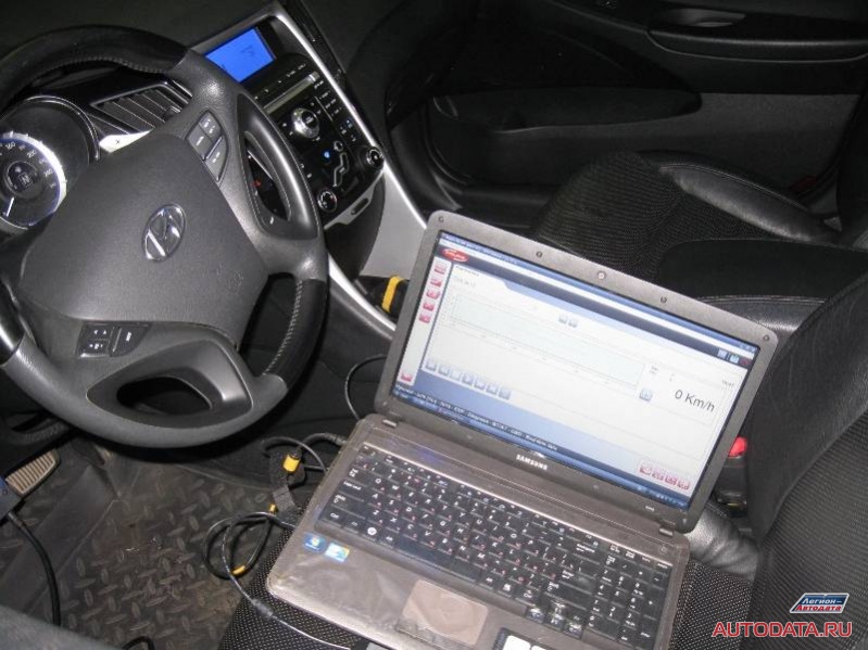
2 - Check faulty sensor shows other data:
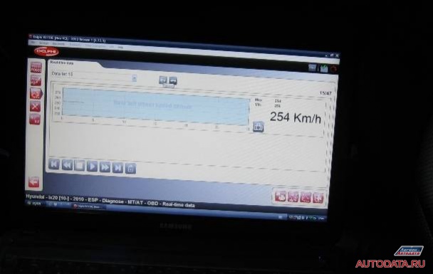
The data obtained confirm that "This speed sensor is faulty." Now you can lift the car on a lift and inspect.
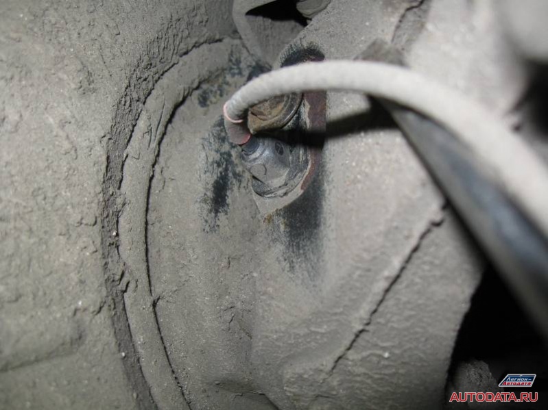
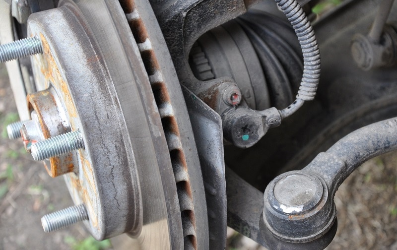
Please take a look with me:
And if you didn’t notice anything, then let’s look at another, serviceable speed sensor:
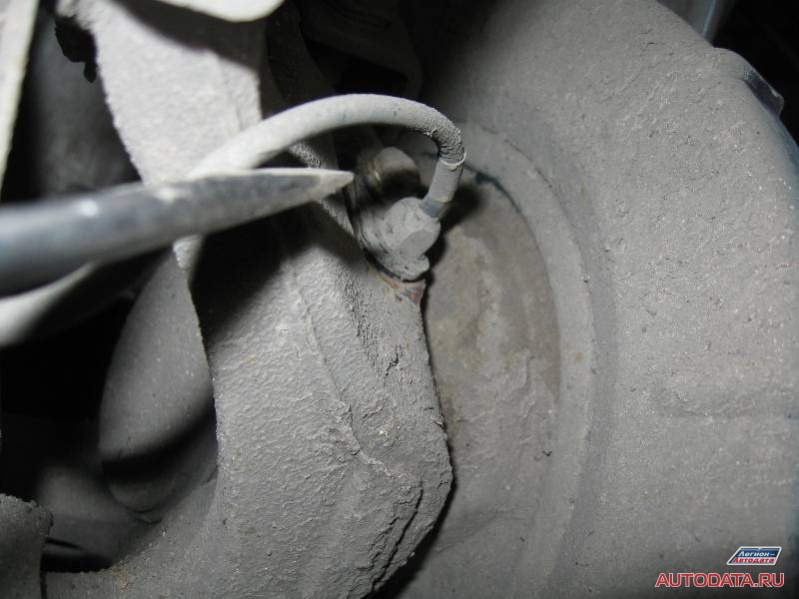
Did you see the difference? If not, then we look at another photo, where I show the cause of the malfunction:
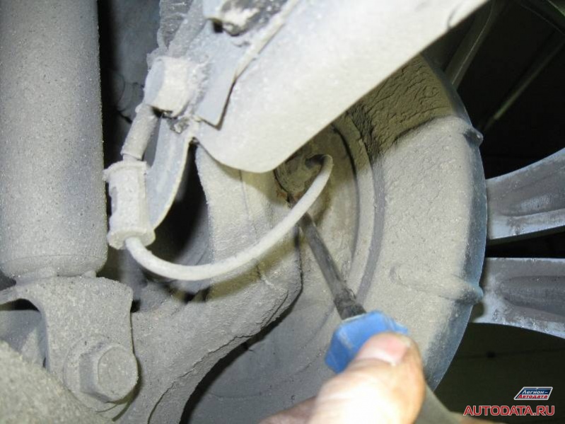
I show the gap with a screwdriver. He is noticeable.
This is the cause of the malfunction: "Too big gap between the sensor and the setting ring".
Where did this gap come from?
As it turned out, the prehistory of the malfunction is as follows: the owner of the car, a person, probably an advanced one, decided to remove the old sensor on his own and put a new one in its place (most likely, he was on some kind of diagnostics and there he was told where the malfunction lurked).
Here the owner of the car was in for a surprise: he independently installed new sensor, but for some reason the malfunction remained, how is this to be understood? You must be upset, right? So much time wasted, effort, nerves, money.
Here you can finish the story and send an expensive reader towards car services. Like, "they can."
However, this is a controversial issue, "can-cannot."
But let's try to understand right here and now: "WHAT was done wrong? Why didn't it work?". So, point by point:
1. Has been checked Catalogue number speed sensor when buying in a store? It happens that the number differs by a couple of digits, and this should not be so. It is better to take the number that is in the catalog and points specifically to desired sensor speed for a particular vehicle.
2. Has the speed sensor been tested since purchase? Thinking? And there is nothing to think about, now is the age of the Internet, they typed the phrase into the search engine: "checking the abs speed sensor" - and get text and pictures:
3. Compare the old ABS speed sensor with the new one just purchased. Compared? Didn't see any difference? Then you can proceed to point 4. Are there any differences? In sizes? In something else? Then urgently turn around and fly back to the store before it closes - change, urgently change! And don't forget to bring an old sample with you.
4. Attentive and simple very carefully inspect the location of the speed sensor. If there is something to "blow inside" the installation site - do it, thereby clearing the installation well from possible debris. Take a flashlight (carry) and try to look inside - you need to make sure that "everything is clean there." No, you don’t need to climb there with your finger - you won’t feel it. Blow with your mouth? Try it. If you reach out. But it's best to use a pump.
5. Don't believe your eyes. Take a piece of sandpaper (sandpaper)

And carefully wipe (sand) the mounting location for the speed sensor with it. If you remember, in my story this was the cause of the malfunction, the "increased gap", here it is, once again in the photo, remember this moment:
This is all? No matter how. This is where mistakes happen!
Of course, you remember where the harness from the old speed sensor was attached to the car body? That's it - fasten the new tourniquet in the same way. If you do it wrong, wait for a malfunction to occur after ... thousands of km, since an incorrectly fixed harness will definitely fray and give an error.
Now everything seems to be. Successful repairs?
2. Lexus RX330
Standard situation: light on the instrument panel, reading the error, raising the car on a lift, visual inspection. The fault indicates that "the speed sensor is faulty." Experience says, look confirms: "The usual situation":
With such a development of events, given that there is a queue of cars for diagnostics and repairs behind them, it is not worth wasting time.
What is the cost of the sensor? Normal type. It is checked using a conventional tester, according to resistance, it should be about 1 Koma. No, the oscilloscope cannot deploy, connect, and check signals. O it. No, watching something extra with a scanner is also not an option. O it - everything is clear here: "Open circuit".
Experience says, the look confirms: "The usual situation", a sign of the times - from the operating conditions, from old age, the tourniquet frayed and the contact began to be lost. The simplest check: you need to move the tourniquet in different places while looking at the device. If at some point the chain disappears / appears, then the assumption is correct.
Adhesive heat shrink will save the situation. Further compulsory procedure: the client is told what is done, how it is done, what is done and how much time ... but the client interrupts:
- Reliable?
Classic answer:
- The most reliable is the acquisition and installation of a new sensor.
3. Mitsubishi Pajero III
The place of the rupture inside the tourniquet is quickly located. But it is strange - outwardly the tourniquet looks decent, no external damage, why then did the device show no contact? Did the device lie? Well, let's check.
I unwind the harness and carefully examine the wires:
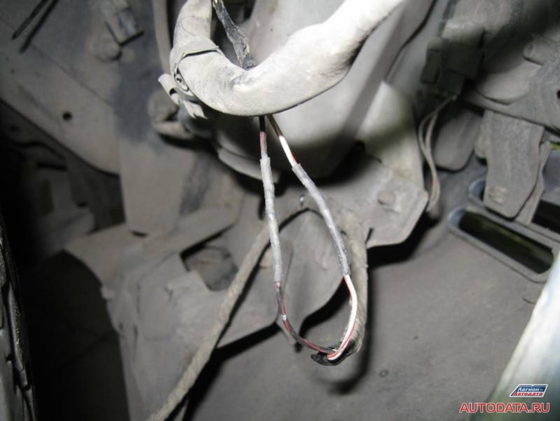
Well, everything is clear: in the previous car service, the work was done not quite efficiently. No, I'm not blaming anyone, just now I'll advise "how to do it better, so that later without claims from the client."
Of course, the repair of all electrical automotive connections must be treated carefully, but especially be scrupulous about those that are constantly in contact with the external environment. Our connection is just that: snow, rain, noxious fumes from road chemicals, and so on.
But outwardly, I repeat, everything was done very well. Even the heat shrink is in place. So what's the reason?
1. Previous experts connected the wires in a "school way", that is, "just twisted together." They just twisted it, and they didn’t even crimp the twist with pliers. This option is possible, but not when repairing automotive wiring. The wires must be twisted, crimped and soldered. Please note that before connecting the wires, they must already be wearing a heat shrink tube!
2. After that, a heat-shrinkable tube is pulled over the junction. Due to the nature of the operation, the heat shrink tube must be with an adhesive layer ( it has an average shrinkage factor and an additional hot-melt adhesive layer on the inner wall. Used for enhanced adhesion)
When purchasing an imported car, many cannot get enough of its comfortable operation. Today, the vehicle is comparable to a computer, as it is stuffed with a lot of electronics designed for comfort and reducing the risk of an accident. Technical equipment, which is responsible for safety, includes such an interesting option as ABS (Antilock Brake System) - Anti-Lock Braking System. Although it has long been established in Russia and has become the standard equipment for all new cars, it still exists, those who happened to encounter it for the first time.
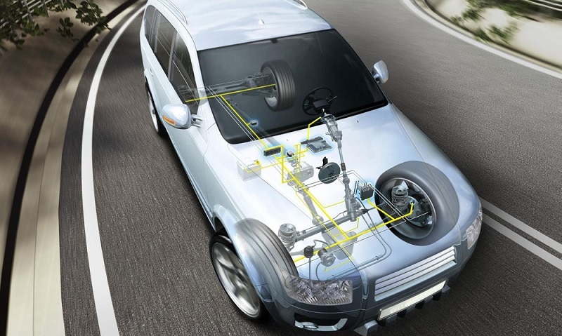
The purpose of ABS is to prevent all four wheels from locking during emergency braking. This allows the vehicle to maintain stability while driving, and on low-traction surfaces (gravel, wet asphalt, snow, ice) cut braking distances. In addition, ABS allows the car, even with the brake pedal fully depressed, to remain controlled and not go into a skid. This multi-component unit, connected to the brake system, is located under the hood between the main brake cylinder and brake caliper cylinders. Consists of ABS system from the main hydraulic unit for modulating fluid pressure, a system of sensors that monitor the speed and location of the wheels, as well as a computer that processes information from the sensors and sends signals to the main unit.
ABS device
The ABS sensor system monitors the speed of rotation of the wheels and the vehicle itself. At the time of strong pressure on the brake pedal, the sensors determine that auto goes skid and send a signal to the block to reduce the braking force, after which the fluid pressure in the brake line drops and the wheels are unlocked. Moreover, if brake pads not unclenched, then the process is repeated until it returns to normal. In short, the entire work of the ABS is reduced to a cycle of braking - analysis - release.
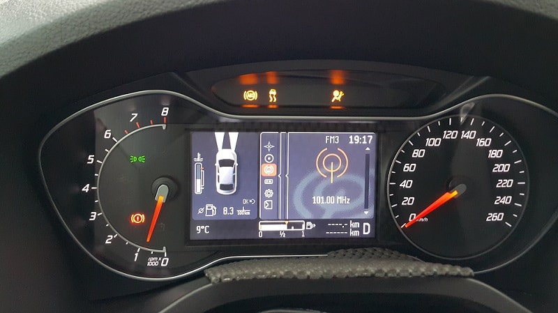
The system works instantly, even before the wheel locks up, a signal about this goes to the dashboard and characteristic shocks appear in the brake pedal. When the inscription on dashboard is permanent, this indicates a malfunction of the ABS. Remember that no matter how active the ABS is in terms of safety, the driver is still the main one. The presence of ABS in the car creates an illusion of safety for many, but in practice, if the system takes control of the turns and exchange rate stability, then in no way reduces the braking distance.
Anti-lock braking system
Risk of ABS failure
Although modern ABS have quite high reliability and can work long term, but, like any other system, they can fail. This happens extremely rarely, because the electronic components are protected by special relays and fuses. If a breakdown does occur, then it does not affect the performance of the entire brake system. ABS module simply turns off, and the brake system starts working normally. It is not worth ignoring the violation, as you can overestimate your capabilities or simply forget yourself during emergency braking. At the first sign of a malfunction, you should not immediately go to the service station, you can try to solve the problem yourself - by diagnosing ABS.
ABS symptoms
The first sign of a failure in the system is an indicator on the dashboard. If the sensor does not go out within 6-10 seconds or turns on while driving, then the system is faulty and not functioning properly. It is important to know that a module failure cannot be detected only in a stationary position. vehicle, some malfunctions can only be recognized when driving at speeds of 25 km/h or more. Before you start looking for problems, remember if you have changed tires on wheels. Since often, in order to save money, many install studded tires in winter period drive wheels only. And since the diameter increases slightly, the wheels begin to rotate at different speeds, which causes the system to flash. In addition, there are times when the sensor lights up during slipping, but, as a rule, in both cases, the indicator lights up briefly or flickers from time to time.
ABS system
The main causes of ABS malfunction
There can be quite a lot of problems with the anti-lock braking system, 4 common causes of ABS malfunction can be distinguished:
- There are breaks in the abs sensor wire or a malfunction of the controller unit. In this case, an error is displayed, signals about the change in angular velocities cease to be given, and the entire system is turned off.
- Failure of wheel sensors. When the ABS, after turning on, passes self-diagnosis and finds an error, but continues to work. The reason is more often in the oxidation of the contacts, a poor connection to the power supply of the system, or a short circuit of the wheel sensors to ground.
- Different tire pressures and tread patterns. Typically, information about angular velocity in this case comes with additional device. When one of the wheels is flat or the tread of one wheel is rougher than on the others, then it starts to slow down. In addition, the same effect can be observed if you install tires with varying degrees wear.
- Mechanical damage to elements - separators wheel bearings, grilles, broken wire near the sensor, wear of the hub bearing, the presence of play and breakage of the wheel sensor rotor. With these breakdowns, the ABS does not start at all. This can also include a failure of the ABS pump.
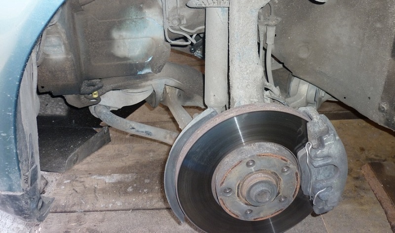
All of the above problems can be solved on your own, sometimes it is enough to identify the problem and repair some ABS units than to make a complete costly replacement of equipment. The most vulnerable in the ABS circuit are the wheel sensors, which are located next to the rotating hubs and axle shafts. The location of the sensors is poor, as dirt and increased play in the hub bearings can cause them to fail, thereby reducing all work anti-lock braking system no brakes.
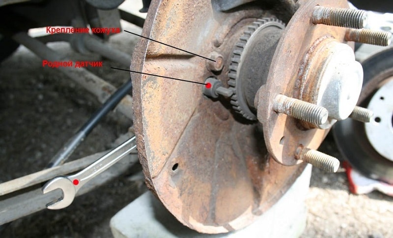
ABS sensor on the wheel of a car
It is not uncommon for the performance of the unit to be affected by the voltage between the battery terminals. If the voltage is reduced to 10.5V or less, the system may abruptly shut itself down after safety block. Since the safety relay always responds to unacceptable surges and voltage fluctuations in the vehicle network. You can eliminate such situations if you do not disconnect the electrical connectors with the ignition on and the engine running. It is necessary to constantly monitor the contacts of the connections on the generator and not start the engine using the "lighting" method.
ABS troubleshooting
The most expensive detail when replacing - the control unit, but as mentioned above, it is protected by a relay, which reduces the risk of its breakdown. The only thing that can knock it out of action is the temperature difference, which we also described above. That's why central part systems can be safely excluded or transferred to the last check point.
Do-it-yourself ABS diagnostics begins with the front wheels:
When an inspection with cleaning the sensor parts did not give results, then perhaps the problem lies in the protection relay, which, as we know, protects electronic circuits from voltage fluctuations in onboard network vehicle. Finding a protective relay is easy if you have the electrical circuit of the machine on hand. The walls of the relay are most often made of aluminum, and the cover is made of plastic. There are two or one fuse under the cover, which can simply blow out, then they need to be replaced.
When this is not the case, then, perhaps, pressure drops have disabled the protective relay itself. To diagnose it, we again take the tester and go through the points:
- Disconnect the connector from the electrical unit, which is located near the relay. The standard connector has 25 pins.
- We put the tester in the position of the voltmeter.
- We connect its probes to the first and second pins of the block. It is easy to confuse them, as they are numbered.
- With the ignition switch on, we measure the twenty-volt voltage of the on-board network.
- If there is no voltage, then we look at the integrity of the fuses and check the minus connector number two, for connection to the ground of the machine.
When no problems are found in this part, we proceed to check the relay itself. It is necessary to remove the protective relay from the car and connect two wires from the battery terminals to the relay terminals marked with numbers 5 and 6. The working relay, when connected to 12 volts, will produce clicks, when there are none, you need to replace it.
ABS sensor replacement
How to Check ABS Sensors - Visual Inspection
Alternatively, the ABS system can be checked using scanner ELM-327. The induction type sensor is an induction coil paired with a toothed metal disk located above the impulse rotor connected to drive shaft or wheel hub. Sensor failure can be found tester, soldering iron, and pinom for repair, but first you should check the sensor cleanly, look for dirt and if there are any, then eliminate them. Next, proceed to measuring the resistance voltage in the node.
Around the pole core there is a winding connected to the magnet. This neighborhood gives magnetic field freely pass to the inductor. And since the rotor rotates and the interdental cavities change, the magnetic flux passing through the winding core changes. Such changes create an alternating voltage, the level of which must be measured. The frequency of the voltage and the amplitude depend on the number of revolutions of the wheel.
ABS bulbs
The pins are attached to the connectors, and the tester measures the resistance of the abs sensor. When measuring resistance rate within 800-1200 ohm, but it is better to look at the passport and check with the valid unit. When the network increases to infinity, a network break has occurred, and if the resistance shows zero, then a short circuit has occurred in the sensor circuit. To spend complete diagnostics sensors, it is necessary to ring the entire wiring of the device with a tester. When everything is normal, the readings will be like this:
- insulation resistance level - more 20kOhm;
- leg - abs sensor front right 7-25 ohm;
- leg - ABS sensor, rear right 6-24 ohm.
When a breakdown is detected during inspection of the sensor, then it is pointless to repair it. If a malfunction is not found, then it is not recommended to intervene in the operation of the central unit on your own. Specialists will review the fault codes previously stored in the device and take appropriate action.
At the end of the 70s it began mass production the first ABS braking system, with which it became possible to increase the level of safety during critical situations related to the need for braking. Various road conditions(wet and slippery surface) or sudden obstacles caused the wheels to lock up during emergency braking of vehicles without ABS.
The consequence of this was the loss of the driver's ability to drive. Vehicles equipped with ABS prevent the wheels from locking up and remain steerable at all times, even in the event of braking to a standstill or emergency braking.
The ABS system consists of the following components:
- Control block
- hydraulic block
— touch sensors of the number of revolutions
- wheel brakes
The control device is the heart of the system. It receives signals from the wheel speed sensors and evaluates them. From this data, information is added about the slip of the wheels when braking, slowing down or accelerating. In the digital regulator, which consists of two microcontrollers independent of each other and working in parallel for each pair of wheels, this information is processed. The control signals formed on the basis of this information, in the form of executive commands, are sent to the magnetic valves of the hydraulic unit, which carry out the commands of the control device.
The hydraulic unit is located between the master brake cylinder and the caliper brake cylinders. In the caliper brake cylinders, the pressure from the brake master cylinder is converted into a push force that presses the brake pads against the brake pads. brake discs or brake drums. Even in the event of emergency braking, when the driver presses the brake pedal with all his might, the pressure in the brake system after the hydraulic unit remains optimal.
When braking to a complete stop ABS system regulates the pressure in the brake drive system, which must be directed to the direct braking device. It is selected for each wheel individually, depending on whether the wheel is slowing down, accelerating or is on the verge of complete blockage.
This regulation takes place as follows: The speed sensors determine the speed of the front wheels and the differential rear axle(for rear-wheel drive and all-wheel drive vehicles), as well as the number of revolutions rear wheels. This data is required by the control device to calculate the circumferential speed of the wheels. As soon as the control device calculates that one or more wheels are at the threshold of blocking, a command is given to the solenoid valves and the return pump of the corresponding wheel. Each front wheel receives such an influence from "its" magnetic valve that the maximum possible braking effect is achieved, excluding it complete blocking. And this happens regardless of the other wheels. In rear-wheel drive and all-wheel drive vehicles that have only one RPM sensor on the rear axle differential, the wheel with the highest "tendency" to lock up determines the value brake pressure for both wheels. As a result, the wheel with the best friction coefficient is braked somewhat less, and the braking distance is somewhat longer, but the car's handling in this case is still much better. In vehicles with touch sensors for each of the rear wheels, the regulation is the same as for the front wheels.
The control device controls the solenoid valves in three different operating positions:
- in the first working position (pressure formation) master cylinder and brake caliper cylinder are connected to each other. This means that the intake valve is open and the exhaust valve is closed. The pressure can build up unhindered.
- in the second operating position (holding pressure), the connection between the master cylinder and the caliper brake cylinder is interrupted. The pressure in the brake drive system remains constant. This means that a signal is given to the intake valve and the valve therefore remains closed, preventing pressure build-up.
- in the third operating position (pressure reduction), the pressure in the brake drive system decreases. This means that on Exhaust valve a pressure release signal is given and it opens. At the same time, the pressure is reduced by turning on the return pump. Inlet valve closed.
Three different operating positions allow the pressure in the brake drive system to be increased or decreased in a stepwise cycle, thanks to the step action on the solenoid valves. When the ABS system is activated, these working positions are changed 4-10 times per second, depending on the characteristics of the road surface.
If a fault is detected in the system, it immediately shuts down. The brake system of the car in this case continues to work efficiently, but without ABS assistance. About system failure ABS driver signals emergency light bulb on the front panel. Depending on the year of manufacture of the car and type ABS, there are several ways to troubleshoot or diagnose, but you need to start with the simplest:
- faulty fuses
Inspection of the fuse box eliminates the first source of failure if you make sure that all fuses associated with the ABS system are in working order.
- visual check
It is necessary to inspect the connectors, determine if there are any frayed wires that could lead to a possible short circuit whether there are any traces of contamination or mechanical damage on the speed sensors and/or on the wheels of the sensors and whether all ground connections are in order.
Unfortunately, it often happens that the tires are incorrectly sized, which can later also cause the failure of the ABS system.
- it is also necessary to check the condition and presence of play, wheel hub bearings.
- it is necessary to check the working brake system for brake stand, a leak test is also required.
If no fault is found during these checks, further measurements should be made. There are various possibilities for this. They depend, for example, on the year of manufacture and type of vehicle and on the test equipment available. If the ABS system is adapted for diagnostics, it is possible, using a special diagnostic tool, to get acquainted with the information from the fault bank and request the value of the values and parameters. If a diagnostic tool is not available or the ABS system is not suitable for diagnostics, subsequent measurements can be made using an oscilloscope or a tester. However, it is very important to always have wiring diagram tested system.
Experience has shown that most faults are caused by faulty connectors, broken wires, or a broken ground connection. These faults are usually easy to identify with a tester or oscilloscope.
Before measuring, make sure the vehicle battery is fully charged so that during the measurement you can notice possible voltage drops on the conductors/connectors.
- If the system is OK, the ABS warning light goes out 2 seconds after the ignition key is turned to the ON (II) position.
- The ABS visual indicator will illuminate if the ABS electronics module detects any malfunction. However, the ABS warning light may come on under the following conditions (ABS OK):
- Only drive wheels rotate
- Jammed one of the drive wheels
- The side slip of the wheels began during the skidding of the car
- ABS works for too long time interval.
- The car was in the zone of strong electromagnetic interference
- If a malfunction occurs during operation and the ABS indicator lights up, then, depending on the nature of the malfunction, the visual indicator may go out either immediately after the system returns to a working state (temporary malfunction), or only when the ignition is turned off.
- Fault codes 61 or 62: The ABS visual indicator goes out immediately after the system returns to a healthy state.
- Fault codes 11, 13, 15, 17, 31, 32, 33, 34, 35, 36, 37, 38, 54, 71, or 81: The ABS warning light will go out only after the ignition is turned off, regardless of whether the fault was temporary or not.
- Fault codes 12, 14, 16, 18, 21, 22, 23, 24, 41, 42, 43, 44, 51, 52, or 53: The ABS visual indicator will only go out after the ignition is turned off, then the engine is restarted and drove some distance, and the ABS malfunction did not recur during the trip.
Visual indicator of the brake system
The visual indicator of the brake system is located on the instrument panel. It lights up in the following cases:- The car is set to the parking brake
- Small level brake fluid in the reservoir of the main brake cylinder
- The ABS electronic unit detects a malfunction EBD systems(electronic rear axle brake force regulator)
System Trouble Codes (DTCs)
- In mind electronic block The ABS can store any number of detected trouble codes. If a fault code that has already been stored in memory is stored in memory, then it is written in place of the old code and does not take up additional space.
Thus, if the same malfunction occurred repeatedly, then only one code of this malfunction will be recorded in the memory. - The fault codes are displayed in the order of their position in the stack: the most recent fault code written will be read first.
- Fault codes are stored in an electronically reprogrammable read-only memory (EEPROM). Therefore, information from this memory is not lost when the power is turned off. battery and turning off the ignition. To erase the fault codes stored in the memory, you should do the actions specially provided for this.
Self-diagnosis system
- There are two possibilities for self-diagnosis:
- Initial diagnostics when the ignition is turned on:
Carried out immediately after turning the ignition key to the ON (II) position during the time when the ABS visual indicator is on - Diagnostics carried out at certain intervals of time:
This diagnosis is continuously performed immediately after the completion of the initial diagnosis and until the moment the ignition is turned off.
- Initial diagnostics when the ignition is turned on:
- If the self-diagnosis system detects a malfunction, then the following actions are performed:
- The ABS and brake system warning light comes on on the instrument panel (the last warning light does not always come on)
- A fault code is stored in the memory of the ABS electronic unit
- ABS functions stop
Recoil on the brake pedal
During ABS operation, the hydraulic pump creates an additional increase in pressure in the system. This is felt in the form of a characteristic kickback on the brake pedal.Hydraulic pump motor
- The hydraulic pump motor is activated when the ABS is in operation.
- At the beginning of the movement of the car, if the ignition was turned off before, the ABS electronic unit performs a test check of the hydraulic pump electric motor. At this point, you can hear the noise from turning on the electric motor, which is not a sign of any malfunction.
How to troubleshoot ABS after reading fault codes
The ABS troubleshooting algorithms assume the actual presence of faults. In this case, the ABS visual indicator on the instrument panel should be lit. The brake warning light may or may not be on. If the ABS visual indicator is off, do not follow the troubleshooting charts. In this case, the algorithms are not applicable.The female connectors shown in the figures have a single contour line; fork connectors have a double contour line.


