The instrument panel was stock Vladimirskaya, slightly improved ... namely 1. uniform diode backlight, 2. PWM brightness control, 3. Smooth turning on and off the backlight when the engine starts 4. All possible indicator lights are connected.
I absolutely did not like the tidy from 31105, I found it in Moscow tidy from 3111, produced by RAR (Riga).
The price was even cheaper than the new one from 31105
Studied material:
www.drive2.ru/cars/gaz/31 …rnal/4035225266124025366/
www.drive2.ru/cars/gaz/31 …/288230376152422866/#post
www.drive2.ru/cars/gaz/31 …/288230376152404924/#post
www.drive2.ru/cars/gaz/24 …/288230376152246368/#post
Stage 1
In addition to tidy for installation You need to buy 2 connectors. They fit from: Skoda Octavia, Golf 4, Passat B5, Audi A6…

specifically mine - from the Skoda Octavia.
Then, having disassembled the pads, you need to add the missing wires to the terminals (the terminals are all in the block, but without wires).
After the wires are inserted, we test the tidy for performance

Stage 2
All the tables and diagrams that are on the Internet, according to the links above, came up to me ... but there are errors everywhere ... both in polarity and in purpose. Therefore, I have compiled my purely table “for internal use” and I advise you to do this in a MANDATORY order.
With just a few entries:
1. What block
2. Purpose of the wire
3. The color of the wire in the block (they are also VAG)
4. Signal polarity
5. Color in car wiring

table in progress
When everything is connected, we get something like this picture


Stage 3
Installation of tidy on the torpedo.
I chose the method indicated by the first link at the beginning of the article, it took a lot of time.

left mount

right mount


Installed

Installed

backlight

from afar
At first, I wanted to install additional. backlight as in his old tidy … but as it turned out, the backlight of PP 3111 is quite enough in the evening and at night … it is uniform!
Issues identified after installation:
1. Almost all signaling devices on the PCB are designed for the supply of mass! therefore, for such indicators as - open doors, heated mirrors and a rear stele, and I don’t remember what else ... I need to purchase a relay converter from + to - ... I found this only stood only for opening the doors.
2. The temperature indicator does not show correctly!
On 3111 there is no tidy temperature sensor on the thermostat ... apparently they are paired with MIKAS there ... the treatment of this bug is at the stage of reflection ... as I decide, I will unsubscribe here.
3. The tidy can show the outboard temperature ... but I did not find which sensor to connect to it.
To control the systems, the GAZ car is equipped with a combination of instruments in which control devices are installed: a voltage gauge, a tachometer, a speedometer, an engine temperature gauge, an oil pressure gauge, a fuel level gauge and signaling devices. The connection of the contacts of the instrument cluster is shown in the electrical diagrams below, and you can see the location of the electrical connectors in the photographs. The information is provided as a guide to do-it-yourself troubleshooting and do-it-yourself instrument panel replacement.
Scheme and contacts of the Gazelle instrument cluster

Connector XP1
1 Coolant temperature sensor
2 Selection of emergency coolant temperature
3 Emergency low engine oil pressure
4 Oil pressure sensor
5 Fuel level sensor
6 ———-
7 ———-
8 Open bus doors
9 ———-
10 Open interior doors, hood or trunk
11 ———
12 ———
13 Malfunction of the electronic brake force regulator (EBD)
Connector XP2
1 Battery
2 Switching on the starboard turn signal lamps
3 Switching on the lamps of the turn signal indicator of the left side
4 Applying the parking brake
5 High beams
6 Switching on the front fog lamps
7 Gearbox illumination
8 Turning on side lights
9 Turning on the rear fog lights
10 ———
11 Turning on the center differential lock
12 Downshifts
13 Oil pressure sensor type
XP3 connector
1 Housing for analog signals
2 Ignition
3 Corps
4 Tachometer high voltage input
5 Low voltage tachometer input
6 Turn on low beam headlights
7 Battery discharge
8 Ignitions
9 Low brake fluid level
10 Speed sensor
11 Speedometer output to on-board computer
12 Activate heated rear window
13 Malfunction of anti-lock braking system (ABS)
XP4 connector
1 Diagnostic indicator(-)
2 Signaling device for diagnostics (+) and activation of engine preheating (+)
3 Brake lining wear
4 Turn on engine preheating (-)
5 ————-
6 ————-
7 ————-
8 ————-
9 —————
10 ————-
11 Low washer fluid level
12 Low coolant level
13 Low engine oil level


The pin assignment of instrument clusters of the 38.3801 family in various versions is shown in the table:
| Output Destination | 38.3801 | 382.3801 | 385.3801010 |
| Carburetor choke control lamp | X1.1 | X1.1 | X1.1 |
| Coolant temperature gauge | X1.2 | X1.2 | X1.2 |
| Control lamp of an overheat of a cooling liquid (-) | X1.3 | X1.3 | X1.3 |
| Low oil pressure warning light | X1.4 | X1.4 | X1.4 |
| Oil pressure gauge | X1.5 | X1.5 | X1.5 |
| Fuel gauge | X1.6 | X1.6 | X1.6 |
| Fuel reserve indicator lamp (-) | X1.7 | X1.7 | ― |
| Warning lamp for unfastened seat belts | X1.8 | ― | |
| Test (-) | X1.9 | ― | |
| Control lamp of open doors (-) | X1.12 | X1.10* | |
| Oil overheat warning lamp | X1.11 | X1.11* | |
| Circuit 30 (permanent power) | ― | X2.2 | |
| Combined STOP warning lamp output | X2.2 | ― | |
| Control lamp of the right index of turn | X2.3 | X2.3 | X2.3 |
| Control lamp left direction indicator | X2.4 | X2.4 | X2.4 |
| Parking brake warning lamp | X2.5 | X2.5 | X2.5 |
| Control lamp of inclusion of a high beam of headlights (+) | x2.6 | x2.6 | x2.6 |
| Control lamp of inclusion of fog lamps (+) | X2.7* | ||
| Pilot lamp trailer direction indicators (+) | ― | ||
| Downshift indication (-) | X2.8* | ||
| Center differential lock indication (-) | X2.9 | X2.9* | X2.9* |
| Seat heating control lamp (+) | X2.10 | ― | |
| Control lamp of inclusion of back fog lamps (+) |
X2.11* |
||
| Control lamp of inclusion of dimensional lighting (+) | X2.7 | X2.12 | X2.12 |
| Instrument lighting circuit | X2.13 | X2.13 | X2.13 |
| Catalytic Converter Overheat Warning Lamp | x2.8 | ― | ― |
| Airbag Warning Light (+) | X2.11 | ― | ― |
| STOP indicator lamp | X3.6 | ― | ― |
| ABS warning lamp (-) | X3.1 | X3.1 |
X3.1, inverse |
| Weight (-) | X3.2 | X3.2 | X3.2 |
| Power (+) speedometer | X3.3 | X3.3 | X3.3 |
| Weight (-) speedometer | X3.4 | X3.4 | X3.4 |
| Tachometer (high voltage input) | ― | X3.5 | X3.5* |
| Tachometer (low voltage input) (-) | ― | X3.6 | X3.6 |
| Tachometer (in the course of the generator) | X3.7 | ― | ― |
| Control lamp of a passing range of headlights (+) | X3.7* | ||
| Control lamp of heating of back glass (+) | X3.8 | X2.1* | X3.8 |
| Speedometer output to onboard computer | X3.9 | X3.9 | X3.9 |
| Speedometer input | X3.10 | X3.10 | X3.10 |
| Brake Fluid Level Warning Light (-) | X3.11 | X3.11 | X3.11 |
| Power (+) control lamps and instruments | X3.12 | X3.12 | X3.12 |
| Battery discharge warning lamp | X3.13 | X3.13 | X3.13 |
| Oil level warning lamp | X4.1 | X4.1* | X4.1* |
| Control lamp CHECK ENGINE (+) | X4.2 | X4.2 | X4.2 |
| Common output of CHECK ENGINE control lamps and heating of glow plugs (-) | X4.3 | X4.3 | X4.3 |
| Brake pad wear warning lamp (-) | ― | ― | X4.4* |
| Glow plug warning lamp (+) | ― | ― | x4.5 |
| Coolant level warning light (-) | X4.8 | X4.8* | X4.8* |
| Washer fluid level warning light (-) | X4.9 | X4.9* | X4.9* |
| Power steering fluid level warning light (-) | X4.10 | X4.10* | X4.10* |
| Control lamp for the presence of water in the fuel filter (+) | ― | ― | X4.11* |
| Burnt out lamp indicator (-) | X4.11 | X4.11* |
Instrument cluster of the old type 384.3801-10

New type instrument cluster 385.3801-10

GAZ Gazelle business 4x4 Titanium - pinout

1 - not connected
2 - 382.3801 has an open door signaling device (may not be). You can run a wire to the limit switch on the driver's door.
3 - 382.3801 has an oil overheating signaling device (may not be). You can run a wire to the TM-108 overheat sensor, put the sensor itself into the crankcase.
4 - 385.3801 has an open door signaling device (may not be). You can run a wire to the limit switch on the driver's door.
5 - 382.3801 test. If ground is applied to this contact, then the brake fluid level, oil overheating, open doors and coolant overheating indicators light up. Can be connected to a button or relay. In the second case, the relay winding is connected to ground and the wire from the lock to the starter (that is, when the starter is turned on, the lamps will be tested).
6 - 382.3801 has an indicator of unfastened seat belts (may not be).
7 - 382.3801 has a fuel reserve indicator. Connect the blue wire with the red stripe.
8 - fuel gauge. Connect to pink wire with red stripe.
9 - oil pressure indicator. At 382.3801, run a wire to the sensor (you need a VAZ-2106 tee) from GAZ under the ZMZ-406 engine. At 385.3801, if you put the sensor, it will squeak about low pressure at XX, so the sensor is not needed, you need to connect the wire from the tidy to ground through a resistor, select it experimentally.
10 - emergency oil pressure alarm. Connect to the gray wire with the blue stripe.
11 - signaling device for engine overheating. It can be connected to the overheating sensor ТМ-111-02. The sensor itself must be in contact with the coolant.
12 - coolant temperature gauge. Connect to green wire with white stripe. The pointer will exaggerate the readings, you can connect a resistor to the wire break, select it experimentally.
13 - signaling device for covering the air damper of the carburetor. Connect to a gray wire with an orange stripe if the car is carb.
14 - for 382.3801 the signaling device can stand, it will light up when the mass is applied.
15 - low gear signaling device (may not be), will light up when mass is applied.
16 - differential lock signaling device (may not be), will light up when mass is applied.
17 - for 382.3801, the seat heating indicator will light up when a plus is applied.
18 - rear PTF signaling device (may not be), will light up when a plus is applied.
19 - side lights signaling device. Connect to yellow wire.
20 - instrument lighting lamps. Connect to white wire.
21 - for 385.3801, the counter is powered. Connect to a permanent power supply (red-white wire of the stop switch).
22 and 23 - signaling devices for the indicator of the right and left turns, respectively. Can be connected together and connected to a blue wire with a white stripe (the arrows will light up with the left or right turn signal), or to the emergency gang switch: blue - right, blue-black - left, insulate the blue wire with a white stripe (each arrow will correspond to the inclusion of its own turn signal).
24 - parking brake signaling device. Connect to brown wire.
25 - headlight high beam signaling device. Connect to green wire with black stripe.
26 - front PTF signaling device (may not be), it will light up when a plus is applied.
27 - ABS signaling device. When mass is applied, it will light up.
28 - for 385.3801 rear window heating indicator. Lights up when positive is applied.
29 - speed signal output to the on-board computer. If it is, then take the speed signal from this contact.
30 - to the vehicle speed sensor.
31 - signaling device for low brake fluid level. Connect to the pink wire with a blue stripe that goes to the lamp above the cigarette lighter.
32 - power supply for lamps and appliances. Connect to orange wire with blue stripe.
33 - battery charge indicator. Connect to brown wire with white stripe.
34 - mass. Connect to black wire.
Wow I wrote so much...
35 - speedometer power supply. Connect to orange wire.
36 - weight of the speedometer. Connect to white wire with black stripe.
37 - tachometer. Connect to the brown wire with a blue stripe, but if the reading drops, connect to pin 38.
39 - for 385.3801, the low beam signaling device (may not be), will light up when a plus is applied.
40 - low oil level indicator (may not be), lights up when mass is applied.
41 - if the machine is injection, connect to the orange wire too.
42 - if the machine is injection, connect to the remaining wire (I don’t know the color), it went to the 8-terminal block on the old tidy.
43 - brake pad wear indicator (may not be), lights up when mass is applied.
44 - signaling device for glow plugs.
45 and 46 - not connected.
47 - low coolant level indicator (may not be), lights up when mass is applied.
48 - low washer fluid level indicator (may not be), lights up when mass is applied.
49 - signaling device for low power steering oil level (may not be), lights up when mass is applied.
50 - signaling device for burnt out lamps for 382.3801 or the presence of water in the fuel filter for 385.3801 (may not be), it will light up when the mass is applied.
51 and 52 - for 382.3801 signaling devices (may not be), it will light up when mass is applied.
The purpose of the elements on the instrument panel GAZ

1 - voltmeter indicates the voltage in the on-board network of the GAZ vehicle;
2 - control lamp of the engine management system;
3 - reserve (or abs malfunction indicator lamp on a Volga GAZ car equipped with an anti-lock braking system);
4 - light panel "STOP". Lights up simultaneously with one of the warning lamps for malfunctions, if further movement with this malfunction is prohibited;
5 - control lamp for turning on the left turn signal. The lamp lights up simultaneously with the left turn indicators. If one of the indicator lamps fails, the control lamp flashes at a double frequency;
6 - control lamp for emergency drop in brake fluid level. The lamp lights up when the fluid level drops (below the minimum allowable) in the reservoir of the main brake cylinder. As the brake pads wear out, it is necessary to top up the brake
liquid;
7 - odometer (total mileage counter);
8 - speedometer indicates the speed of the car;
9 - control lamp for turning on the parking brake. The lamp burns at the raised lever of a lay brake and the included ignition. 10 - control lamp for turning on the right turn signal. The lamp lights up simultaneously with the right turn indicators. If one of the indicator lamps fails, the control lamp flashes at a double frequency;
11 - reserve;
12 - warning lamp for unfastened seat belts (installed on some Volga GAZ 31105 cars);
13 or 18 - control lamp for emergency oil pressure drop in the engine lubrication system. The lamp should light up when the ignition is turned on and go out after starting the engine. If the light stays on after the engine has started, or comes on while the engine is running, stop the engine immediately and check the oil level. The level is normal - the engine is faulty. For a car with high mileage, the lamp may light up when the engine is idling;
14 - reserve (for installing additional control lamps);
15 - fuel gauge. The instrument shows the approximate amount of fuel in the tank. Divisions are marked on the scale 0 - empty tank; 1/2 - half a tank; 1 - full tank:
16 - fuel reserve control lamp. The lamp turns on when the remaining fuel in the tank is less than 8 liters; 17 - oil pressure indicator in the engine lubrication system allows you to evaluate the technical condition of the engine;
19 - control lamp for turning on seat heating (for GAZ 31105 vehicles with heated seats);
20 - coolant temperature gauge allows you to control the temperature of the engine;
21 - control lamp for switching on external lighting (side light);
22 - control lamp for overheating of the coolant turns on when the temperature of the coolant rises above the permissible value;
23 - control lamp for switching on the high beam headlights. The lamp turns on when the high beam headlights are turned on;
24 - button for setting the daily mileage counter to zero. In order to reset the meter readings, you must press the button;
25 - car daily mileage counter. To reset the meter readings, press the zero setting button (pos. 24);
26 - tachometer. The device shows the frequency of rotation of the crankshaft of the engine;
27 - battery discharge indicator lamp. The lamp should light up when the ignition is on, and go out after the engine is started. Burning lamp with the engine running may indicate a malfunction of the generator or its circuits.
Replacing the old instrument cluster with a new one
Many car owners of a Gazelle or Volga car with an old-style instrument panel tend to change it to a new-style instrument panel, in which most of the indicators have been replaced with modern LEDs, and such an instrument panel looks much prettier and brighter.

So, to remove the instrument cluster, first remove the lining by unscrewing the four screws. Then unscrew the four screws securing the combination; disconnect electric sockets and remove a combination of devices. Repair the instrument cluster by block replacement of faulty instruments. To replace devices, remove the protective glass and unscrew the nuts securing the defective device on the reverse side.

The reason why many drivers install the Gazelle Business dashboard is that it looks better. The second reason why you should buy this particular version of the panel is the functionality and an increased number of opportunities to monitor the performance of the car.

The euro type panel has 2 large dials - a speedometer and a tachometer, as well as 2 small ones, which show the amount of gasoline and the temperature of the coolant. The rest of the information about the state of the nodes and the errors that have occurred is displayed using the burning signaling devices in the middle of the panel. A simpler design significantly relieves the driver's attention.
Video instruction for panel installation
The Gazelle is a very popular truck in Russia. On the basis of the GAZ-3302, a lot of cars for other purposes are also produced. These are both public transport and passenger minibuses. What unites all these models? They are united not only by a common frame structure, but also by a single instrument panel. Gazelles of different years of production were equipped with different dashboards. Well, let's look at exactly what and what are the features of each shield.
Purpose
The function of any "device" is informational. This also applies to the Gazelle Business instrument panel. On a small area in the dashboard there are all the necessary indicators, lights and scales. Usually the shield is located behind the wheel, in front of the driver's eyes. But there are exceptions. For example, in the UAZ "Hunter" the panel is located in the center. But we will not consider the tidying of this car yet. Let's get back to our Gazelles. Outwardly, their panels are three to five round dials with several signaling sensors. In any shield, the main dials are:
- Speedometer.
- Tachometer.
They are the largest and are located in the center. In addition, there are a lot of auxiliary elements on the instrument panel ("Gazelle" of the old model and the new one). These scales inform the driver about:
- The current temperature of the engine (namely, the coolant in the internal combustion engine jacket).
- Oil pressure in the system.
- Fuel level in the tank.
- Voltage in the onboard network.
If we consider more modern tidy, information about the current time will also be displayed here.
Where is it installed?
Note that the Gazelle instrument panel can also be found on other cars. These are Sobol and Volga. The device has the same wiring diagram. Externally, these shields look identical.
Types
There are several types of panel data:
- The old sample "Euro-1". Installed on cars from 1994 to 2002 inclusive.
- The old model "Euro-2". These shields can be found on "Gazelles" with a new "muzzle" (with drop-shaped headlights).
- New sample. They are installed to this day on Nexts, starting with Gazelle Business.
Below we will consider the features of each Gazelle instrument panel.
Panel "Euro-1"
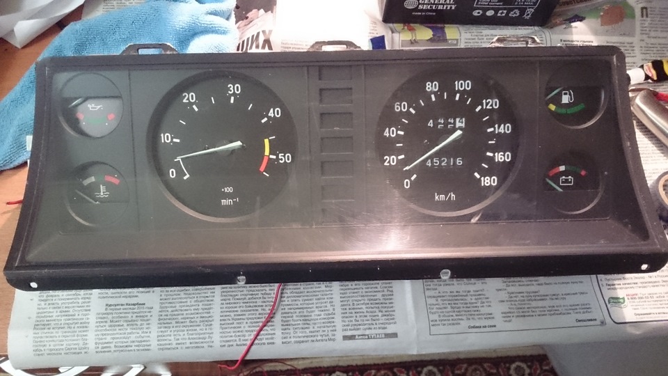
This tidy was installed both on the Sobol and on the Gazelle of all modifications. What design she has, the reader can see in the photo below.
Remotely, this shield resembles a Zhiguli-seven panel. But still, this is an original design. There are no electronic signs here. There is only:
- Speedometer.
- Tachometer.
- Oil pressure (not level) sensor.
- Network voltage indicator.
- fuel and antifreeze temperature.
In this form, the shield was produced for about eight years. No changes were made during this period.
Panel "Euro-2"
This tidy is also called "Riga". It was also installed on the Volga, in particular the 31105 series. This shield has a slightly different design and appearance. It was developed specifically for the new torpedo, with a rounded visor. New sensors did not appear here, but the location of some dials has changed.

The speedometer scale has now become larger in diameter, and the antifreeze temperature and oil pressure sensors are combined into one “well”. The changes also affected the odometer. If earlier the main odometer was designed for a run of up to one hundred thousand (after which it was reset to zero), now its boundary line is one million kilometers. Of course, few people have met a Gazelle with a similar mileage, but still the addition of one digit greatly facilitated some work and maintenance (no need to guess and think when to replace the chain, and even overhaul the engine). According to the reviews of the owners, the new Riga Gazelle instrument panel is much more convenient to use. Also, the arrow of the tachometer and speedometer does not “walk” here. Starting in 2003, these scales are electrically powered, not wired. The readings have become more accurate.
"Euro-3"
For the first time, such a tidy appeared on Gazelle Business cars. The old-style Gazelle instrument panel went out of fashion, and all the Gazelle workers began to install the updated panel in their car. The owners of the Volg were also engaged in the same alterations. Indeed, the new shield has become much more informative, convenient and practical. What can I say, the design is much more modern. According to reviews, with him the interior looks fresher and not so dull. What the updated tidy looks like in practice, the reader can see in the photo below.

But it is worth noting that this shield has slight differences in design. So, on some models, the instrument scales had a darker shade. But this did not affect the information content in any way - reviews say. Another feature of the new shield is the presence of a sound indication. Now the driver can hear a characteristic signal if:
- The fuel level has dropped to the minimum mark.
- The engine temperature has increased to 105 degrees Celsius or more.
- The handbrake was not released. Remarkably, the signal is triggered only when the car started moving at a speed of 2 or more kilometers per hour.
The new tidy received large modern dials. Now the speedometer and tachometer scales are in opposite places (compared to the "Riga"), and their diameter has become the same. On the left is the fuel gauge, and on the right is the coolant temperature sensor. But where did the mains voltage and oil pressure indication go? The answer is simple - this data is in the on-board computer. It is located in the "well" of the tachometer. By default, only the time is shown here. But if you press the button on the right, you can switch the mode. So, the driver can find out the data from the voltmeter and oil pressure in real time.
Remarkably, when the oil drops below 0.2 bar, a blinking window with a sensor will light up.
On the left side there is a digital odometer. Above shows the total, and below - the daily mileage. It is reset by pressing the button on the left. Also on the panel of the new sample there are 20 indicators (including ABS and EBD), which light up in the event of a malfunction of a particular system.
Principle of operation
The algorithm of action for all panels is the same. Each light bulb and arrow interact with a specific element. So, the readings of both speed and mileage come from a sensor that is screwed onto the box. Engine information comes from the crankshaft sensor. And the voltage data comes from the generator terminals. What is noteworthy: if you do not connect the voltage contact, the car will not charge even with a working generator. This problem is accompanied by a red battery light on the panel. If it is on, it means that a break has occurred and the wire does not fit the contact of the tidy connector. As for oil pressure and, this information comes from the terminals of the corresponding sensors.
Problems
Are there any problems associated with the above shields? Unfortunately, the owners are faced with the problem of tidy malfunction. This happens least often at the very first panel, the old model. It works like clockwork. The Riga panel may inaccurately give information about the level of oil pressure. Also, the speedometer often jams here. Along with this, the odometer refuses to work. But most of the complaints, surprisingly, are caused by the new instrument panel of the Gazelle Next and Business.

So, the most common malfunction is zeroing the mileage (moreover, total) on a run of 60 thousand kilometers. Because of this, it is impossible to accurately control the passage of maintenance and a number of other repair operations. But that is not all. The daily mileage is also reset - reviews say. This happens if the voltage in the network is less than 11.5 volts. Also, the data is erased if the terminals are removed from the battery.
What else?
The Gazelle instrument panel of the new model does not work even when installed in the old Gazelle. You need to mount it correctly - just throwing pads with contacts will not work. For a successful installation, you need a pinout of the Gazelle Business instrument panel.
Among other malfunctions, it is worth noting the freezing of the speedometer and tachometer needles in one position. Most owners start to panic and completely disassemble the shield. But you don't have to. The problem lies in the insufficient contact of the connectors.
Installation
To install the panel, you must remove the old shield. To do this, you need to dismantle the steering wheel using a special puller and unscrew a couple of screws from the decorative lining of the shield. You should also unscrew the bolts securing the tidy itself.

To do this, you need an "8" head. After that, you can remove the old panel and put a new one in its place. But as we said earlier, just throwing the connectors will not work. Need a pinout for the Gazelle Business instrument panel. There are four pads in total - XP1, 2, 3 and 4. Let's consider how to connect each:
- XP1. The first, fifth, sixth, seventh contacts are closed to ground. As for the rest, they are connected to the sensor signals. The first contact is the air damper cover relay, the third is DTOZH, the ninth and eleventh are the oil pressure sensor and the fuel level in the tank, respectively. The rest of the contacts are "Reserve". We do not touch them and do not connect anything to them.
- XP2. Contacts number two, four, nine close to ground. On the "plus" are the terminals, everything from the fifth to the thirteenth.
- HRS. Terminals number two and thirteen are connected to the positive contact + 12V. The first, eighth and twelfth terminals are closed to ground. The sixth connector is the speedometer speed sensor, the ninth is the ignition coil, the eleventh goes to the engine control unit.
- XP4. Here, almost all contacts must be connected to the "mass". This applies to connectors from the first to the seventh inclusive. Only the sensor for the presence of water in the fuel filter (if any) and the glow plug switch go to the "plus". These are slots number eight and nine, respectively.

By the way, if the car does not have an ABS and EBD system, the outputs to these sensors must be turned off. How? It is enough to connect them to the "mass".
So, we found out what the Gazelle dashboard is, what types it is and how it is connected.
Not marked
Dashboards
Factory labeling of the panels looks like "3110.3801" for "old" panels and "3110.3801010" for "new" panels.
The instrument panels of the two types differ, of course, in design, as well as in the mechanisms for the execution of pointers. On the "old" panel there are mainly miliammeters, on the "new" - stepper motors. Those. new dashboard (roughly) - controlled by controllers. Indicators of the old - lamps, new - LEDs. A buzzer is built into the new instrument panel.
Notes:
"New" panels appeared as basic ones for the restyling of the GAZ-3110. The series did not go.
The first samples of the new panels were installed on the assembly line on the GAZ-31105 "Chrysler" at the end of 2005. The "old type" instrument panels were categorically not suitable for this engine (and were not installed).
Later, dashboards of the "new type" began to be installed on cars with ZMZ (cars powered by "distributed injection"). Admittedly, not very often, since there was a struggle to reduce the cost of the machine in production, and old dashboards, of course, are cheaper than new ones.
New panels were installed only on ZMZ-406, ZMZ-405 and Chrysler engines. Only old instrument panels were installed on the ZMZ-402 and GAZ-560.
Only "new" instrument clusters were installed in the "restyled" salon.
Old instrument clusters are found on cars with ZMZ-40621 "Euro 2" until 2008, when this engine was no longer installed. For Euro 3, the old combinations were not installed.
Dashboards GAZ-31105 index 3110.3801 were produced by two manufacturers, index 3110.3801010 - seven. Official suppliers of GAZ - " RAR" And " autodevice". For 3110.3801010, " CJSC "ZE and M-Line""and in 2008" Accountmash". Remaining (" Tochmash", "ACCI", "ATG") on the GAZ-31105 instrument panels were not supplied.
Manufacturers of instrument panels instead of the factory "3110." often assign their own index.
The connection diagrams for the instrument panels that were supplied to the conveyor are identical. The rest - may differ from the factory ones.
1. JSC "" Riga
2. OJSC " Rigas autoelektroaparatu rupnica (RAR)"Riga for the version with a diesel engine. Tachometer up to 5000 rpm.
3. OJSC " Plant "Avtopribor""Vladimir
382.3801010 - used on GAZ-3110 and GAZ-31105 with ZMZ-402, ZMZ-406 engines.
- 383.3801010 - diesel GAZ-560


On the dashboard for the GAZ 31105 version with a diesel engine, there is another tachometer.

4. OJSC " Rigas autoelektroaparatu rupnica (RAR)"Riga - AR 130.3801000-02

5. OJSC " Plant "Avtopribor""Vladimir
385.3801010 - base.

385.3801010-01 - base with a different design of scales and edging (under "chrome").

385.3801010-10 - engines ZMZ-405, 406 "Euro 0" and "Euro 2". It differs from the basic one in an extended set of signaling devices. - 385.3801010-11 - the same as -10 with a different design of scales and edging.

385.3801010-30 - "Chrysler" engine.
- 385.3801010-70 - all ZMZ and "Chrysler" engines. Appeared in 2007. The mode with which engine to work is programmed.

- 385.3801010-75 - the same as -70, only one LCD screen (left). Cheaper option. No clock, oil pressure and voltmeter.
- 385.3801 Lux - apparently an option for retail sale.
6. COMPANY " ZE and M-Line"Cheboksary
3110.3801000-10 - engines ZMZ-405, 406 "Euro 0", "Euro 2", "Euro 3".
- 3110.3801000-40 - GAZ-560 diesel (only GAZelle)
- 3110.3801000-50 - under "restyling". Possible for all engines. LCD-2 displays readings from an external air temperature sensor. Added indicators of control lamps for power steering fluids, coolant, washer and oil level in the crankcase. Made to order, not mass produced.
7. OJSC " Accountmash" Kursk
4505.3801010-01 - ZMZ engines.
- 4505.3801010-04 - "Chrysler" engine.
8. OJSC " VPO "Tochmash""Vladimir
3110.3801000-05
- 3110.3801000-10
- 3110.3801000-30 - "Chrysler" engine.
9. Company " Electronics ATPP" Saint Petersburg
The location of the vehicle controls complies with all UNECE safety standards and regulations. For the convenience of the driver to use the handles, buttons and control devices, which are located on the instrument panel, symbolic signs of functional purpose were applied to them during production.
Dashboard GAZ-3110
1 – side blowers for supply ventilation, which are designed to direct the air flow from the heater or ventilation system (at the choice of the driver or passenger). Air flows are regulated by turning the handle (to the right and to the left) or the grate itself (up and down);
2
– decorative speaker grille;
3
- storage shelf;
4
– the glove box serves for placement of small things. You can open it by pressing the lock handle to the right, and the lamp of its illumination also turns on. When the drawer door is closed, the lamp goes out accordingly;
5
- the plug closes the reserve socket for the switch of any additional equipment installed by order of the owner;
6
– Antenna raise/lower control switch (the motorized antenna, like the switch, is not included in the standard package). When you press the top edge of the key, the antenna extends, and the bottom edge retracts;
7
– the switch of back antifog lanterns. The rear fog lights come on when the central switch is moved to position II and the dipped headlights or fog lights are switched on. When you turn on the rear fog lights, the backlight of the switch key is turned on;
8
– heater control panel;
9
- an ashtray, to open it, you need to pull its handles towards you, and to completely remove it, press the plate to extinguish cigarettes. The cigarette lighter is located under the ashtray cover, turns on when you press its handle all the way. The cigarette lighter coil heats up after about 15–20 seconds and the cigarette lighter returns to its original position with a click. You can turn on the cigarette lighter again no earlier than after 20-25 seconds. There is a backlight in the cigarette lighter socket, which lights up when the outdoor lighting is turned on;
10
– gearshift lever. The gearshift pattern is printed on the lever handle. When the reverse gear is engaged, the reversing light lamps in the rear lights are automatically switched on;
11
- the alarm switch turns on all direction indicators in a flashing mode when the button is pressed. At the same time, the lamp in the switch button lights up with a red light in a flashing mode. Pressing the button again turns off the alarm;
12
- steering wheel;
13
– ignition switch (lock). The switch has a factory built anti-theft device. The switch has the following key positions: 0 - all consumers are off, the key cannot be removed, the anti-theft device is off; I - the ignition and instruments are on, the key cannot be removed, the anti-theft device is turned off; II - the ignition and starter are on, the key is turned to failure with overcoming the force of the spring and cannot be removed, the anti-theft device is turned off. This position of the key is not fixed; when released, the key returns to position I under the action of the spring. The key can only be turned to position II again after the key has previously returned to position 0; III - the ignition is off, the external lighting, instrument lighting, high-beam headlights, radio equipment are on. The key is removed, when the key is removed, the anti-theft device is turned on. To turn off the anti-theft device, you need to insert the key into the switch and, slightly turning the steering wheel to the right or left, turn the key to position 0;
14
– an accelerator pedal;
15
- the carburetor air damper drive handle (installed on cars only with the ZMZ-402 or ZMZ-4021 engine) is pulled towards itself to close the air damper before starting the engine;
16
– brake pedal;
17
- socket for connecting a portable lamp;
18
– clutch pedal;
19
– the handle of a drive of the lock of a cowl. The hood lock is unlocked by pulling the handle towards you;
20
– the headlight range control knob. The corrector is needed to eliminate the influence of the load in the car on the direction of the headlight beam. The handle has four positions: I - only the driver or the driver and the front passenger; II - driver and four passengers; III - the driver, four passengers and a load of 50 kg in the luggage compartment; IV - the driver and a load of 50 kg in the luggage compartment;
21
– the switch of a sound signal at pressing on its button activates a sound signal;
22
– the lever of the switch of indexes of turn and light of headlights. The lever has the following positions: I – all consumers are off (fixed position); II - left turn indicators are on (non-fixed position); III - left turn indicators are on (fixed position); IV - right turn indicators are on (non-fixed position); V - right turn indicators are on (fixed position). When the lever is in positions II–V, the control lamps in the instrument cluster light up with a flashing light, respectively. 49
or 53
. When the steering wheel is returned to the straight ahead position, the switch lever is automatically set to position I; VI - (toward yourself) the main beam of the headlights is on at the position I of the handle 25
central switch (non-fixed position). If the handle 25
the central switch is in position II, then each time you press the lever, the dipped beam switches to high beam and vice versa;
23
– a combination of devices;
24
– the wiper and washer switch lever. The windshield wiper and washer only operate when the ignition is on. The switch lever has four fixed and one non-fixed positions. When moving the lever in a plane parallel to the steering wheel: I - (fixed position) wiper and washer off; II - (fixed position) the wiper operates at low speed; II - (fixed position) the wiper operates at high speed; IV - (fixed position) intermittent wiper operation. Moving the lever along the steering column towards the steering wheel to position V (non-fixed position) from any other position activates the washer. When the washer is turned on from position I, the wiper blades perform one full stroke;
25
- the handle of the central light switch has five fixed positions - three when the handle is moved in the axial direction and two when it is rotated around the axis: I - all consumers are off; II - side light, instrument cluster and license plate lighting are on; III - the same consumers are included as in position II, and the dipped or main beam of the headlights; IV - interior lighting cover is on; V - instrument lighting is turned on in the maximum intensity mode;
26
– Heater fan switch. The switch key has three fixed positions: upper - the fan is off, middle - low fan speed, lower - maximum fan speed;
27
– the switch of a mode of an electric heating of back glass. Electric heating can only be switched on when the ignition is on. The switch key has three fixed positions: upper - heating is off; medium - moderate heating (dim backlighting of the key); lower - intensive heating (bright key illumination);
28
- Central blower. The purpose and principle of operation are the same as for side blowers. 1
;
29
– the switch of antifog headlights. When you press the switch key, if the handle 25
the central switch is in position II, the fog lights are switched on. At the same time, the backlight of the key lights up;
30
- radio tape recorder;
31
– Nozzle of an obduv of a windshield;
32
- fuse block cover. Under the cover are blocks of fuses for electrical circuits. To access them, you need to move the nameplate with the inscription "Volga" to the right and, having picked up (for example, with a screwdriver) the edge of the cover through the opened hole, remove it from the socket, overcoming the force of the spring holders;
Dashboard GAZ-3110. part 2

33
– the electromagnetic fuel level indicator works only when the ignition is on. When the ignition is off, the arrow is located at the beginning of the scale. The scale has divisions: 0 - empty tank, 1/2 - half tank, 1 - full tank;
34
– the control lamp of the minimum reserve of fuel in the tank (with an orange color filter) is constantly on when the remaining fuel in the tank is less than 8 liters;
35
– the signal lamp of an emergency drop in oil pressure (with a red light filter) lights up when the ignition is switched on and warns that the pressure in the engine lubrication system is below normal. It is allowed to light the lamp at idle and during heavy braking. With an increase in the frequency of rotation of the crankshaft, the lamp should go out. The movement of a car with a burning lamp is prohibited;
36
– a control lamp of inclusion of heating of seats (functions only in the presence of the heating installed by request);
37
– The electrothermal coolant temperature indicator works only when the ignition is on and shows the temperature of the coolant in the engine cooling system. When the ignition is off, the arrow is located at the beginning of the scale. The scale has divisions from 40 to 120 °C, the division value is 20 °C. The presence of the pointer in the red zone of the scale indicates overheating of the coolant;
38
– the control lamp of inclusion of dimensional light (with the light filter of green color) specifies inclusion of dimensional light in headlights and back lanterns;
39
– the control lamp for turning on the trailer direction indicators (with a green light filter) turns on when the lever is 22
a switch for direction indicators and headlights in positions II–V with the trailer lighting and signaling system connected (if any);
40
– the control lamp of inclusion of a high beam of headlights (with the light filter of blue color) indicates inclusion of a high beam of headlights;
41
- the daily mileage counter indicates the distance traveled in kilometers (the rightmost digit of the counter, which has a color different from the rest, shows the mileage in hundreds of meters). It is set to zero when the vehicle is stationary by pressing the meter reset button 42;
42
– button for resetting the daily mileage counter;
43
- the induction type speedometer shows how fast the car is currently moving. The scale has divisions from 0 to 200 km/h, the division price is 10 km/h. The speedometer drive is electric from a sensor mounted on the gearbox housing;
44
- an electronic type tachometer shows the engine speed. The scale has divisions from 0 to 8, the division price is 0.5. To find out the crankshaft speed in min -1, you need to multiply the tachometer readings by 1000;
45
– the signal lamp of the storage battery discharge (with the light filter of red color) lights up at inclusion of ignition. Immediately after starting the engine, the lamp should go out. If the lamp is lit while the engine is running, it indicates that there is no charging current due to a malfunction of the alternator or voltage regulator. Driving the car with the lamp on will lead to a complete discharge of the battery;
46
- The voltmeter monitors the voltage in the car's on-board network. The scale has divisions from 8 to 16 V. In the range of 8–12 V, the division value is 2 V, in the range of 12–16 V - 1 V. The presence of the voltmeter needle in the red zone of the scale indicates an unacceptably low voltage in the vehicle's on-board network;
47
- the control lamp of the engine management system (with an orange color filter) operates on vehicles with a ZMZ-4062 engine. With a working control system, it lights up for 5-10 seconds after the ignition is turned on and then goes out, indicating that the engine is ready to start. The burning of the lamp in various modes when the car is moving indicates the failure of any elements of the engine control system;
48
- the signal lamp "STOP" (with a red color filter) lights up when the ignition is switched on simultaneously with any of the signal lamps 35
, 50
, 52
or 55
. If these warning lamps come on while driving, further operation of the vehicle until the malfunction is eliminated is prohibited;
49
- the control lamp for turning on the left direction indicator (with a green light filter in the form of an arrow) lights up with a flashing light when the left direction indicator is turned on synchronously with it. The blinking of the control lamp with a doubled frequency indicates a lamp burnout in any direction indicator;
50
– a signal lamp for an emergency drop in the brake fluid level (with a red color filter) lights up when the brake fluid level drops below the “min” mark on the brake master cylinder reservoir;
51
- the total mileage counter shows the distance traveled in kilometers; the rightmost digit of the counter, which has a different color from the others, shows the mileage in hundreds of meters. After a run of 100,000 km, a new countdown cycle begins;
52
– the signal lamp of inclusion of a parking brake (with a light filter of red color) lights up at the included ignition by a flashing light if the car is braked by a parking brake;
53
– control lamp for turning on the right direction indicator ( see subsection 3.1.6.4);
54
- the control lamp for covering the air damper of the carburetor (with an orange light filter) functions only on vehicles with engines ZMZ-402 and ZMZ-4021 and lights up when the handle is pulled out towards you 15
air damper drive, indicating the carburetor air damper remaining closed after starting the engine;
55
– signal lamp of an overheat of a cooling liquid of the engine (with the light filter of red color) lights up at a temperature of a cooling liquid of 102–109 °C. When the lamp is on, it is necessary to stop the engine and eliminate the cause of overheating;
56
- The oil pressure indicator shows the pressure in the engine lubrication system. The indicator scale has divisions from 0 to 6 kgf/cm 2 .
GAZ-3110

1 – the switch of control of serviceability of signal and control lamps of a combination of devices. When you press any edge of the switch key, the control and signal lamps light up. 48 (see fig. Dashboard), 50 , 55 and backup alarms for seat belts and catalytic converter overheating;
2
– windshield washer jet heating switch (if there is a heating system). Pressing a key turns on its backlight;
3
, 4
, 5
, 6
– plugs of reserve sockets for installation of switches of the additional equipment.


