Diagnostics of ABS failures
Wiring diagram for ABS warning lampAbout failures Driver's ABS notifies a special control lamp located on dashboard car. As soon as the ABS control module detects a violation in the system, it turns it off. The braking system continues to function normally.
Diagnostics of the ABS condition is performed every time the engine is started and is accompanied by a short-term operation of the control lamp. Within a short time after starting, the lama should automatically turn off.
If the ABS warning light comes on and stays on while driving, first check that parking brake fully released and the brake system is functioning properly. If everything is normal, then the ABS has failed. Do the following simple checks first:
a) Check condition brake calipers and wheel cylinders;
b) Check up a condition and reliability of fastening of contact sockets of electroconducting of the control module ABS and wheel gauges (see the Head Onboard electrical equipment);
c) Check the appropriate fuses (see Chapter Onboard electrical equipment).
Failures of a control lamp ABS
The cause of failures in the functioning of the ABS warning lamp may be an open or short circuit in its electrical circuit.
The ABS warning lamp does not come on when the ignition is switched on
Try to turn on the ignition without starting the engine - if the other indicator lamps that are part of the instrument cluster work properly, proceed to the next step of the test, otherwise the necessary restorative device of the instrument panel should be made.
Switch off the ignition. Remove the instrument cluster, remove the ABS warning lamp and check its condition. If the lamp is burned out, replace it, otherwise proceed to the next step of the test.
Disconnect the contact pair B62 / F45 and measure the voltage between the chassis ground (-) and terminal No. G6 (+) of the B62 connector. If the measurement result is less than 3 V, proceed to the next test step, otherwise, check the condition of the wiring of the corresponding control lamp. Make necessary repairs.
Turn off the ignition, put the control lamp under test in its original place and install the instrument cluster.
Turn on the ignition and repeat the voltage measurement. If the measurement result does not fall outside the range of 10 ÷ 15 V, proceed to the next step of the test, otherwise check the condition of the wiring. Produce the required refurbishment.
Switch off the ignition and perform a voltage test between terminal G6 (+) of connector F45 and chassis ground. If the measurement result is less than 3 V, proceed to the next test step, otherwise check the condition of the relevant wiring. Make necessary repairs.
Switch on the ignition and repeat the test. If the measurement result is less than 3 V, proceed to the next test step, otherwise, check the condition of the wiring of the corresponding control lamp. Make necessary repairs.
Measure the resistance between terminal No. 23 of connector F49 and ground. If the measurement result is less than 5 ohms, proceed to the next step of the test, otherwise, check the grounding of the control module / hydromodulator assembly. Make necessary repairs.
Measure the resistance between ground and terminal G6 connector F45. If the measurement result is less than 5 ohms, proceed to the next test step, otherwise check the condition of the connector and its wiring harness. Make the necessary remedial repairs, if necessary, replace the connector.
Turn off the ignition and check the condition of the connectors in the circuit section between the instrument cluster and the ABS control module, - if there are no signs of poor contact reliability, replace the ABS control module / hydraulic modulator assembly.
The ABS warning lamp does not turn off after starting the engine
Switch off the ignition and make sure that the connector of the ABS control module / hydraulic modulator is fully seated and securely fixed.
Measure the resistance between chassis ground and each (A and B) of the diagnostic terminals (B81). If the measurement result is less than 5 ohms, proceed to the next step of the test, otherwise, check the condition of the corresponding wiring harness, make the necessary remedial repairs.
Switch off the ignition and connect the diagnostic terminal to terminal No. 8 of the B82 diagnostic connector. Disconnect the ABS control module connector and measure the resistance between connector F49 terminal No. 4 and chassis ground. If the measurement result is less than 5 ohms, proceed to the next step of the test, otherwise check the condition of the wiring in the circuit section between the ABS control module and the diagnostic connector, make the necessary remedial repairs.
Run the engine to idle and check for voltage between the B (+) terminal on the back of the generator (power terminal) and chassis ground. If the measurement result is within the range of 10 ÷ 15 V, proceed to the next step of the test, otherwise replace/repair the generator (see Chapter ) and repeat the test.
Turn off the ignition and check the condition of the battery terminals and the reliability of the terminal lugs of the wires on them. Make the necessary corrections if necessary.
Disconnect the ABS control module wiring connector, then start the engine at idle and measure the voltage between terminal No. 1 (+) of connector F49 and chassis ground. If the measurement result is within the range of 10 ÷ 15 V, proceed to the next step of the test, otherwise check the condition of the wiring of the power supply circuit. Make necessary repairs.
Disconnect the contact pair B62 / F45 and turn on the ignition - if the ABS warning lamp does not work, proceed to the next step of the test, otherwise check the condition front harness wiring.
Switch off the ignition and check the condition of the tabs on the control module connector. If the terminals are in order, proceed to the next step of the test, otherwise, replace the control module / hydromodulator (see Section ).
Measure the resistance between terminals No. 22 and 23 of the ABS control module connector. If the measurement result is more than 1 MΩ, proceed to the next step of the test, otherwise replace the ABS control module/hydraulic modulator assembly (see Section Removal, installation and check of serviceability of functioning of assembly of the control module / hydraulic modulator ABS).
Measure the resistance between terminal G6 of connector F45 and chassis ground. If the measurement result is less than 0.5 ohm, proceed to the next step of the test, otherwise, make the necessary reconditioning of the wiring.
Connect the wiring to the ABS control module and measure the resistance between terminal G6 of connector F45 and chassis ground. If the measurement result is more than 1 MΩ, proceed to the next step of the test, otherwise, make the necessary reconditioning of the wiring.
Check the condition and security of the ABS control module connector. If necessary, make the necessary corrections, or replace the control module / hydromodulator assembly.
Unable to read fault codes
If the test lamp turns on and off normally, but does not display the initial code (DTC 11 - see below) when entering the diagnostic mode, turn off the ignition and perform the checks.
Wheel sensor failures
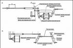
Failures of wheel sensors lead to violation of serviceability of functioning of ABS. The connection diagram of the wheel sensors is shown in the illustration.
An open in the wheel sensor circuit or an excessively high input voltage level (DTC Nos. 21, 23, 25 and 27)
Disconnect the wiring from the ABS control module and measure the voltage between the appropriate wheel sensor terminal No. 1 and chassis ground. If the measurement result is less than 1 V, proceed to the next test step, otherwise replace the sensor.
Switch on the ignition and repeat the previous test. If the measurement result is less than 1 V, proceed to the next test step, otherwise replace the sensor.
Turn off the ignition and connect the wiring to the sensor. Measure the resistance between terminals Nos. 11 and 12 (DTC 21)/9 and 10 (DTC 23)/14 and 15 (DTC 25)/7 and 8 (DTC 27) of connector F49. If the measurement result is within the range of 1 ÷ 1.5 kOhm, proceed to the next step of the test, otherwise check the condition of the wiring in the area between the control module and the sensor. Make necessary repairs.
Measure the voltage between ground and terminal No. 11 (DTC 21)/9 (DTC 23)/14 (DTC 25)/7 (DTC 27) of connector F49. If the measurement is greater than 1 V, repair the short in the circuit between the sensor and the ABS control module. If there is no voltage (less than 1 V), turn on the ignition and repeat the test. If there is still no voltage (less than 1 V), proceed to the next step of the test, otherwise check the condition of the wiring between the sensor and the ABS control module, if necessary, eliminate the cause of the short circuit.
Measure the gap between the sensor and the rotor around the entire perimeter of the latter. In case of insufficient clearance (see. Specifications) adjust it by selecting an adjusting shim (26755АА000). If the gap is too large, remove the spacers and replace the rotor (assembly with swivel assembly) or failed sensor. After completing the adjustment, proceed to the next step of the test.
Ignition OFF, and measure the resistance between the wheel sensor connector terminal #1 and chassis ground. If the measurement result is more than 1 MΩ, proceed to the next test step, otherwise replace the sensor.
Switch off the ignition and connect the wiring to the wheel sensor. Measure the resistance between chassis ground and terminal No. 11 (DLC 21)/9 (DLC 23)/14 (DLC 25)/7 (DLC 27) of connector F49. If the measurement result is more than 1 MΩ, proceed to the next step of the test, otherwise check the condition of the wiring in the section of the circuit between the sensor and the ABS control module. Make necessary repairs. If the wiring is OK, replace the control/hydraulic modulator assembly.
Restore the original connection of all connectors, clear the processor memory (see below) and repeat the procedure for reading diagnostic codes. If no change (in the direction of improvement) has occurred, replace the ABS control module/hydraulic modulator assembly. If new codes appear, proceed to perform the appropriate check. If the failure did not repeat, therefore, the malfunction was temporary, - once again make sure that all contact connections are securely fastened.
Short in wheel sensor circuit (DTC #22, 24, 26 & 28)
Switch off the ignition and check the tightness of the sensor mounting bolts (32 Nm). Tighten the fasteners if necessary and proceed to the next step of the test.
If you cannot use an oscilloscope, move on to checking the mechanical condition of the rotor and cleaning the components.
If you have an oscilloscope, jack up the car and place it on jack stands so that the wheels are completely off the ground. Turn off the ignition and connect an oscilloscope between terminals No. C5 (+) and B5 (-) (DTC 22) / C6 (+) and B6 (-) (DTC 24) of connector B62 or 1 (+) and 2 (-) (DTC 26) / 4 (+) and 5 (-) (DTC 28) of connector F55.
Turn on the ignition and, while rotating the corresponding wheel of the car, follow the oscilloscope readings. The amplitude of the sinusoidal signal displayed on the screen should not exceed the range of 0.12 ÷ 1.00 V, - if this condition fails, or the waveform is malformed, proceed to the next test step.
Check wheel hub runout. If the measurement result is less than 0.05 mm, proceed to the next step of the test, otherwise replace the hub.
Switch off the ignition. Disconnect the wiring from the appropriate wheel sensor. Measure the resistance between terminals No. 1 and 2 of the sensor connector. If the measurement result is within the range of 1 ÷ 1.5 kOhm, proceed to the next step of the test, otherwise replace the sensor.
Measure the resistance between ground and terminal No. 1 of the wheel sensor connector. If the measurement result is more than 1 MΩ, proceed to the next test step, otherwise replace the sensor.
Connect the wiring harness to the wheel sensor and disconnect it from the ABS control module. Measure the resistance between terminals Nos. 11 and 12 (DTC 22)/9 and 10 (DTC 24)/14 and 15 (DTC 26)/7 and 8 (DTC 28) of connector F49 of the ABS control module. If the measurement result is within the range of 1 ÷ 1.5 kOhm, proceed to the next step of the test, otherwise, perform the necessary reconditioning of the wiring in the section of the circuit between the sensor and the control module / ABS hydromodulator.
Measure the resistance between chassis ground and terminal No. 11 (DTC 22)/9 (DTC 24)/14 (DTC 26)/7 (DTC 28) of connector F49 of the control module. If the measurement result is more than 1 MΩ, proceed to the next step of the test, otherwise check the wiring between the sensor and the module for a short circuit. Make necessary repairs.
Measure the resistance between ground and terminal No. 23 of connector F49. If the measurement result is less than 0.5 ohm, proceed to the next step of the test, otherwise, eliminate the cause of the ground fault.
Check up reliability of fastening of contact sockets of the module of management ABS and the wheel sensor. Make the necessary corrections. If the contacts are in order, proceed to the next step of the test.
Make sure the car phone/remote control transmitter is installed at a sufficient distance from the wheel sensor wiring harness.
Restore the original connection of all connectors and measure the resistance between ground and terminal No. A5 (DTC 22) / A6 (DTC 24) of connector B62. If the measurement result is less than 0.5 ohm, proceed to the next test step, otherwise replace the shielded harness.
Restore the original connection of all connectors and repeat the procedure for reading diagnostic codes. If no change (in the direction of improvement) has occurred, replace the ABS control module/hydraulic modulator assembly. When new codes appear, go to the appropriate test. If the failure did not repeat, therefore, the malfunction was temporary, - once again make sure that all contact connections are securely fastened.
There are problems with the correct output of the wheel sensor (one or all four) of the information signal (DTC 29)
Assess the condition of the tread and tire inflation pressure. Make appropriate corrections/replacements if necessary.
Check the tightness of the mounting bolts ABS sensors(32 Nm). Tighten the fasteners if necessary and proceed to the next step of the test.
Measure the gap between the sensor and the rotor around the entire perimeter of the latter. In case of insufficient clearance (see Specifications), correct it by selecting an adjusting shim (26755AA000). If the gap is too large, remove the spacers and replace the rotor (assembly with swivel assembly) or failed sensor. After completing the adjustment, proceed to the next step of the test.
If you cannot use an oscilloscope, move on to checking the mechanical condition of the rotor and cleaning the components. If you have an oscilloscope, jack up the car and place it on jack stands so that the wheels are completely off the ground. Turn off the ignition and connect an oscilloscope between terminals No. C5 (+) and B5 (-) (DTC 22) / C6 (+) and B6 (-) (DTC 24) of connector B62 or 1 (+) and 2 (-) (DTC 26) / 4 (+) and 5 (-) (DTC 28) of connector F55.
Turn on the ignition and, while rotating the corresponding wheel of the car, follow the oscilloscope readings. The amplitude of the sinusoidal signal displayed on the screen should not exceed the range of 0.12 ÷ 1.00 V, - if this condition is not met, or the signal has an irregular shape, proceed to the next test stage, otherwise proceed to the next test.
Carefully inspect the wheel sensor and its rotor for signs of damage or contamination. Wipe components, fix any problems.
Check wheel hub runout. If the measurement result is less than 0.05 mm, proceed to the next step of the test, otherwise replace the hub.
Switch off the ignition. Restore the original wiring connection. Clear the processor memory (see below) and repeat the procedure for reading diagnostic codes. If no change (in the direction of improvement) has occurred, replace the ABS control module/hydraulic modulator assembly. When new codes appear, go to the appropriate test. If the failure did not repeat, therefore, the malfunction was temporary, check again the reliability of fastening of all contact connections.
Failures of the control module / hydraulic modulator ABS
Intake (DTC 31, 33, 35 & 37) / Exhaust (DTC 32, 34, 36 & 38) Solenoid Valve Malfunction
Disconnect the wiring from the ABS control module.
Start the engine at idle and measure the voltage between terminal No. 1 (+) of connector F49 of the control unit and chassis ground. If the measurement result is within the range of 10 ÷ 15 V, proceed to the next step of the test, otherwise check the condition of the wiring between the battery, the ignition switch and the ABS control module. Make necessary repairs.
Switch off the ignition and measure the resistance between chassis ground and terminal No. 23 of connector F49. If the measurement result is less than 0.5 ohm, proceed to the next step of the test, otherwise, eliminate the cause of the ground fault.
ABS Control Module Malfunction (DTC 41)
Switch off the ignition. Disconnect the wiring from the ABS control module and measure the resistance between terminal No. 23 of connector F49 and chassis ground. If the measurement result is less than 0.5 ohm, proceed to the next step of the test, otherwise, eliminate the cause of the ground fault.
Check the serviceability of the condition and the reliability of the fixation of the electrical wiring connectors on the ABS control module, generator and battery. Carry out appropriate reconditioning if necessary. If there are no violations of the quality of contacts, proceed to the next step of the test.
Make sure the car phone/remote control transmitter is installed at a sufficient distance from the ABS wiring harnesses.
Switch off the ignition. Restore the original wiring connection. Clear the processor memory and repeat the procedure for reading diagnostic codes. If no change (in the direction of improvement) has occurred, replace the ABS control module/hydraulic modulator assembly. When new codes appear, go to the appropriate test. If the failure did not repeat, therefore, the malfunction was temporary, - once again make sure that all contact connections are securely fastened.
Deviation from the nominal supply voltage level (DTC 42)
Start the engine and warm it up to normal operating temperature. Check if the RPM is set correctly. idle move. Measure the voltage between the B (+) terminal on the rear of the generator and chassis ground. If the measurement result does not fall outside the range of 10 ÷ 17 V, proceed to the next step of the test, otherwise check the state of the charging system (see Chapter Engine electrical equipment
), make the necessary corrections.
Turn off the ignition and check the condition of the battery terminals and the reliability of fixing the terminal lugs of the wires on them. If necessary, clean the contact surfaces of the terminals/lugs. If the terminals are OK, disconnect the wiring from the ABS control module, start the engine at idle and measure the voltage between ground and terminal No. 1 (+) of the F49 connector. If the measurement result is within the range of 10 ÷ 17 V, proceed to the next step of the test, otherwise check the condition of the wiring between the ignition switch and the ABS control module connector. Make necessary repairs.
Switch off the ignition and measure the resistance between terminal No. 23 of connector F49 and chassis ground. If the measurement result is less than 0.5 ohm, proceed to the next step of the test, otherwise, eliminate the cause of the ground fault.
Check up serviceability of a condition and reliability of fixing of contact sockets of electroconducting on the control module ABS, the generator and the storage battery. Carry out appropriate reconditioning if necessary. If there are no violations of the quality of contacts, proceed to the next step of the test.
Switch off the ignition. Restore the original wiring connection. Clear the processor memory and repeat the procedure for reading diagnostic codes. If no change (in the direction of improvement) has occurred, replace the ABS control module/hydraulic modulator assembly. When new codes appear, go to the appropriate test. If the failure did not repeat, therefore, the malfunction was temporary, - once again make sure that all contact connections are securely fastened.
Violation of serviceability of functioning of a control system АТ (DTC 44)
Ignition OFF, and disconnect the two transmission control module (TCM) harness connectors. Also disconnect the electrical wiring from the ABS control module. Measure the resistance between terminal No. 3 of connector F49 and chassis ground. If the measurement is greater than 1 MΩ, proceed to the next step of the test, otherwise, recondition the wiring between the TCM and the ABS control module.
Switch on the ignition and measure the voltage between ground and terminal No. 3 of connector F49. If the measurement is less than 1V, proceed to the next test step, otherwise, perform the necessary reconditioning of the wiring in the area between the TCM and the ABS control module.
Measure the voltage between ground and terminals No. 3 and 31 of connector F49. If the measurement result is within the range of 10 ÷ 15 V, proceed to the next step of the test, otherwise check the condition of the wiring in the area between the ABS control module and the TCM. Make necessary repairs.
Check up a condition and reliability of fixing of contact sockets of modules of management ABS and АТ. If necessary, clean the terminals and proceed to the next step of the test.
Switch off the ignition. Restore the original wiring connection. Clear the processor memory and repeat the procedure for reading diagnostic codes. If no change (in the direction of improvement) has occurred, replace the ABS control module/hydraulic modulator assembly. When new codes appear, go to the appropriate test. If the failure did not repeat, therefore, the malfunction was temporary, - once again make sure that all contact connections are securely fastened.
Valve Relay Malfunction (DTC 51)
Switch off the ignition and disconnect the electrical wiring from the ABS control unit. Start the engine at idle and measure the voltage between terminals No. 1 and 24 of connector F49 of the ABS control module and chassis ground. If the measurement result is within the range of 10 ÷ 15 V, proceed to the next step of the test, otherwise check the condition of the wiring between the ABS control unit and the battery. Make necessary repairs.
Measure the resistance between terminals No. 23 (+) and 24 (-) of the control module connector. If the measurement result is more than 1 MΩ, proceed to the next step of the test, otherwise replace the control unit.
Check up serviceability of a condition and reliability of fixing of contact sockets of electroconducting on the control module ABS, the generator and the storage battery. Carry out appropriate reconditioning if necessary. If there is no violation of the quality of contacts, proceed to the next step of the test.
Switch off the ignition. Restore the original wiring connection. Clear the processor memory and repeat the procedure for reading diagnostic codes. If no change (in the direction of improvement) has occurred, replace the ABS control module/hydraulic modulator assembly. When new codes appear, go to the appropriate test. If the failure did not repeat, therefore, the malfunction was temporary, - once again make sure that all contact connections are securely fastened.
Malfunction of the drive motor / its relay (DTC 52)
Switch off the ignition. Disconnect the wiring from the ABS control module, then turn the ignition key back to the ON position and measure the voltage between the control module connector F49 terminal No. 25 and chassis ground. If the measurement result is within the range of 10 ÷ 15 V, proceed to the next step of the test, otherwise, recondition the wiring in the area between the battery and the control module / hydromodulator. Check the SBF fuse holder.
Switch off the ignition and measure the resistance between ground and terminal No. 26 of connector F49. If the measurement result is less than 0.5 ohm, proceed to the next step of the test, otherwise, repair the ground circuit of the control unit.
Start the engine at idle and measure the voltage between terminal No. 1 of connector F49 and chassis ground. If the measurement result is within the range of 10 ÷ 15 V, proceed to the next step of the test, otherwise check the condition of the wiring in the areas between the battery, the ignition switch and the ABS control module. Make necessary repairs.
Switch off the ignition and measure the resistance between ground and terminal No. 23 of connector F49. If the measurement result is less than 0.5 ohm, proceed to the next step of the test, otherwise, eliminate the cause of the ground fault.
In the course of checking the sequence of operation of the hydraulic modulator valves (see Section Checking the sequence of operation of the ABS hydraulic modulator valves) by ear, check the correct operation of the electric motor. If the motor rotates properly, proceed to the next step of the test, otherwise replace the ABS modulator/control unit assembly.
Check the serviceability of the condition and the reliability of the fixation of the electrical wiring connectors on the assembly of the ABS control module / hydraulic modulator, generator and battery. Carry out appropriate reconditioning if necessary. If there are no violations of the quality of contacts, proceed to the next step of the test.
Switch off the ignition. Restore the original wiring connection. Clear the processor memory and repeat the procedure for reading diagnostic codes. If no change (in the direction of improvement) has occurred, replace the ABS control module/hydraulic modulator assembly. When new codes appear, go to the appropriate test. If the failure did not repeat, therefore, the malfunction was temporary, - once again make sure that all contact connections are securely fastened.
Violation of serviceability of functioning of the gauge-switch of stoplights (DTC 54)
Failure of the sensor-switch of brake lights leads to a malfunction of the ABS.
Check the brake lights for proper operation when the foot brake pedal is depressed. If everything is in order, proceed to the next step of the test, otherwise check the condition of the lamps and wiring of the brake light circuit.
Switch off the ignition. Disconnect the wiring from the ABS control module. Depress the foot brake pedal and measure the voltage between ABS control module connector F49 terminal No. 2 and chassis ground. If the measurement result is within the range of 10 ÷ 15 V, proceed to the next step of the test, otherwise check the condition of the wiring in the area between the brake light sensor-switch and the ABS control module. Make necessary repairs.
Check the condition and reliability of the fixation of the contact connectors of the sensor-switch and the control unit. Make appropriate corrections if necessary. If the contacts are in order, proceed to the next step of the test.
G-Sensor Output Malfunction (DTC 56)
Check the marking of the assembly of the ABS control module / hydraulic modulator, - the code is applied on the surface of the block between the fittings for connecting the hydraulic lines and for models (see Specifications). If the marking corresponds to the configuration of your car, proceed to the next step of the test, otherwise replace the ABS control module / hydraulic modulator assembly.
|
Switch off the ignition. Remove the central console (see the Head Body). Unscrew the G-sensor without disconnecting the electrical wiring from it. Turn the ignition key back to the ON position and measure the voltage between terminals No. 1 (+) and 3 (-) on the outside of the sensor connector R70. If the measurement result is within the range of 4.75 ÷ 5.25 V, proceed to the next step of the test, otherwise check the condition of the wiring in the area between the sensor and the ABS control module. Make necessary repairs. |
Switch off the ignition. Disconnect the wiring from the ABS control module and measure the resistance between terminals No. 6 and 28 of connector F49 of the control module. If the measurement result is within the range of 4.3 ÷ 4.9 kOhm, proceed to the next step of the test, otherwise, perform the necessary reconditioning of the wiring in the area between the sensor and the ABS control module.
Disconnect the electrical wiring from the G-sensor. Measure the resistance between terminal No. 6 of connector F49 and chassis ground. If the measurement result is more than 1 MΩ, proceed to the next step of the test, otherwise, make the necessary reconditioning of the wiring in the area between the sensor and the ABS control module.
Measure the voltage between terminal No. 6 of connector F49 and chassis ground. If the measurement result is less than 1 V, proceed to the next step of the test, otherwise, make the necessary reconditioning of the wiring in the area between the sensor and the ABS control module.
Repeat the last check with the ignition on. If the measurement result is less than 1 V, proceed to the next step of the test, otherwise, make the necessary reconditioning of the wiring in the area between the sensor and the ABS module.
Measure the resistance between ground and terminal No. 28 of connector F49. If the measurement result is more than 1 MΩ, proceed to the next step of the test, otherwise, make the necessary reconditioning of the wiring in the area between the sensor and the ABS control module. If wiring is OK, replace control module/hydraulic modulator assembly.
Turn off the ignition and, without disconnecting the wiring, unbolt the G-sensor. Check up reliability of fixing of contact sockets of the sensor and control module ABS. Turn on the ignition and measure the voltage between terminals No. 2 (+) and No. 3 (-) of the sensor connector R70. If the measurement result is within the range of 2.1 ÷ 2.4 V, proceed to the next step of the test, otherwise replace the sensor.
Tilt the transducer 90° forward and repeat the above test. If the measurement result is within the range of 3.7 ÷ 4.1 V, proceed to the next step of the test, otherwise replace the sensor.
Tilt the transducer 90° backwards and repeat the test again. If the measurement result is within the range of 0.5 ÷ 0.9 V, proceed to the next step of the test, otherwise replace the sensor.
Switch off the ignition. Check the condition and security of the G-sensor connectors and ABS module. Carry out appropriate reconditioning if necessary. If the contact connections are in order, proceed to the next step of the test.
Restore the original wiring connection. Clear the processor memory and repeat the procedure for reading diagnostic codes. If no change (in the direction of improvement) has occurred, replace the ABS control module/hydraulic modulator assembly. When new codes appear, go to the appropriate test. If the failure did not repeat, therefore, the malfunction was temporary, - once again make sure that all contact connections are securely fastened.
Checking the I/O Signals of the ABS Control Module
The map of the location of the contact terminals in the connector of the control module / hydraulic modulator and the wiring diagram of the ABS components are shown in the illustrations.
ABS Wiring Diagram
1 - Assembling the control module / ABS hydraulic modulator |
13 - Right rear wheel outlet solenoid valve |
Map of the location of the contact terminals in the connector of the ABS control module
The waveform taken from the individual terminals of the ABS sensors is shown in resist. illustrations. The list of signals is given in the table.
Reading trouble codes (DTC) ABS
For a list of ABS DTCs, refer to Specifications on this chapter.
Reading DTCs using SSM
Get the SSM reader ready for use.
Connect to SSM diagnostic cable and refill the cartridge.
Connect the SSM diagnostic cable to the DLC connector located on the left under the vehicle's instrument panel.
Turn the ignition key to the ON position (do not start the engine) and power on the SSM.
In the Main Menu of the reader screen, select the section (Each System Check) and press the YES key.
In the "System Selection Menu" field of the screen, select the subsection (Brake Control System), confirm the selection by pressing the YES key.
After displaying information about ABS type press the YES key again.
In the "ABS Diagnosis" field of the screen, select the item (Diagnostic Code(s) Display) and confirm the selection by pressing the YES key.
Select (Current Diagnostic Code(s)) or (History Diagnostic Code(s)) in the "Diagnostic Code(s) Display" field of the screen, press the YES key.
Reading current data
Enter the menu subsection (Brake Control System), wait for the ABS type message to appear on the screen and press the YES key.
In the "Brake Control Diagnosis" field of the screen, select the item (Current Data Display & Save) and confirm the selection by pressing the YES key.
In the Data Select Menu field, select (Data Display) and press YES.
Use the scroll buttons to move through the list displayed on the screen and select the data you are interested in. The list of output data is given in the table below.
|
monitor screen |
Output type |
Units |
|
Speed corresponding to the rotational speed of the right front wheel |
Right front wheel sensor data |
km/h or miles/h |
|
Speed corresponding to the rotational speed of the left front wheel |
Data provided by the left front wheel sensor |
km/h or miles/h |
|
Speed corresponding to the speed of the right rear wheel |
Right rear wheel sensor data |
km/h or miles/h |
|
Speed corresponding to the rotational speed of the left rear wheel |
Data provided by the left rear wheel sensor |
km/h or miles/h |
|
Brake light switch |
Status of the sensor-switch |
On or Off |
|
Brake light switch |
Brake light switch voltage output | |
|
G-sensor input |
G-sensor signal voltage (vehicle acceleration data) | |
|
Valve relay signal |
Valve relay signal |
On on or off |
|
Motor relay signal |
Motor relay signal |
On on or off |
|
ABS signal to TCM |
The signal issued by the ABS control module to the TCM AT |
On on or off |
|
ABS warning lamp |
Data output about the operation of the ABS warning lamp |
On on or off |
|
Motor Relay Monitoring |
Output of motor relay activation data |
high or low |
|
Valve relay monitoring |
Valve relay activation data output |
On on or off |
|
CCM signal |
ABS function signal from the ABS control module to the AT TCM |
On on or off |
Reading DTCs without using SSM
Remove the diagnostic connector located next to the driver's seat heater unit.
Turn off the ignition and connect the diagnostic terminal to terminal No. 8 of the connector.
Turn the ignition on, the ABS warning lamp will go into diagnostic mode and start flashing the fault codes (DTCs) stored in the processor memory.
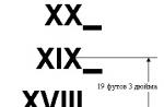
The test start code (11) is always displayed first, then all other codes are output in turn, starting with the last one. After the last code is displayed, the cycle repeats for 3 minutes. Examples of code output are shown in the illustration. If there are no codes stored in the memory, the control lamp will display only the start code (11).
Deleting codes from processor memory
Using SSM
From the Main Menu of the SSM reader, select (2. Each System Check) and press the YES key.
In the System Select Menu, select (Brake System), press YES, wait until the ABS type information is displayed, then press YES again.
In the "Brake Control Diagnosis" field of the screen, select the item (Clear Memory) and confirm the selection by pressing the YES key.
After the reader displays the messages “Done” and “Turn ignition OFF”, power off the SSM and turn off the ignition.
Without SSM
Within approximately 12 seconds, repeat the procedure for connecting / disconnecting the terminal three times with the duration of each phase (On and Off) of at least 0.2 s.
Successful completion of the memory clearing is confirmed by the flashing of code 11 by the control lamp.
The ABS system is installed on many modern cars. Toyota Corolla 2007, 2008, and cars of more recent years of production were also equipped with this system. However, often motorists are faced with the following problem: the ABS sensor lights up. This means that you need to check the ABS or the sensor itself.
How is ABS used?
The ABC system is necessary to stabilize braking and improve the behavior of the wheels on difficult areas roads: for example, it should work when hard braking By slippery road, upon entry. The task of the ABS unit is to prevent the brakes from locking up and the car body skidding: in this way, the driver will be able to maintain controllability. It will be possible to press the brake pedal all the way down without thinking about the intermittency of this action, which the car will perform itself.
At emergency braking slippage will not occur, which is why it is important to ensure that the anti-lock block is in good working order.
How does the anti-lock brake system work?
In order to understand whether the system works correctly, you need to know how it should work in good condition. On the Toyota Corolla 120, the system works as follows: as soon as braking begins, sensors installed on the wheels of the car monitor the initial braking impulse.
The hydraulic cylinders are controlled via an electrical wire to prevent slippage, as a sensor sends a signal to the system to possible blocking brakes. Thanks to this, there is a strong grip on the road and skidding does not occur.
On vehicles without a sensor, the driver must control the situation by removing his foot from the brake pedal and pressing it again, however, it is quite difficult to accurately track the moment when the car lost traction, and skidding becomes inevitable.
Why might errors occur?
Corolla 150 is a reliable car, however Russian conditions operation may not affect the sensors in the best way. Most often, if dashboard appears ABS icon, you need to check for malfunctions of the ABS sensor.
When the engine is turned on, the light should light up and go out after a certain time: this is a normal reaction of the system to turn on, however, if the ABS lamp turns off again, this indicates a malfunction in the control unit or sensor. The notification may light up the following reasons: the fuses are out of order, the wires of the electrical system do not pass impulses well, the sensor itself is faulty, the control unit is out of order, communication with the sensor was lost.
If the lamp does not burn constantly, blinks frequently, then the problem may be in the operation of the car's generator.
How to check for a problem?
Check ABS work Toyota Corolla is best in a specialized car service, where they can determine exactly what the problem is and fix it. If the car has an on-board computer, the master will be able to read the error number and understand what's wrong.
However, some manipulations can be carried out independently.
Without this element, the device will not work. You can find the fuse block under the hood: check the fuses, connectors, replace blown ones if necessary.

The control unit is also under the hood. You can find the control unit by the tubes coming from the brakes and wires. The control unit can receive mechanical damage, so you need to inspect it first visually. First, the electrical wire will need to be removed from it. Check if water has entered the unit: if it is wet, it needs to be dried.
After washing, a similar problem can also occur, as moisture gets on the wiring. A wet wire shorts out and the wheel sensor cannot communicate with other parts of the system; in this situation, you need to wait until the wire dries.
Serious repairs may be required if the hub bearing is defective. To do this, you need to accelerate the car to at least 80 km / h and listen: if a distinct hum is heard, then the bearing needs to be replaced. Most often, the front one breaks, but if, for example, the rear left requires repair, the bearings are replaced on both sides of the axle. If the rear bearing fails, it is not necessary to change the front right or left element.
In the same situation, you can check the brakes. Pay attention to how the car behaves when you press the pedal, whether it skids, whether the impact on it is noticeable from the working ABS. You will quickly understand if the system is not working. If the ABS sensor does not work, you will need to raise the car on a lift: each wheel has its own sensor, so you need to check them one by one. The connectors may oxidize, the sensors themselves may become clogged with dirt. You also need to check the integrity of the wires.

Conclusion
It is possible to use the car while the ABS light is on, but it is better to have the vehicle repaired, as the wheels may lose traction on slippery surfaces, which will affect your safety. Serious repairs are recommended to be done in the workshop, but you can determine what the problem is on your own, for which you can use a minimum of tools.
Required entry: This article can be considered both as a "guide to action", and as just an attempt to explain the principles of work ABS systems for all those who have not yet encountered or have just begun to study this system. Do not look here for answers to all the questions that arise, because, as practice shows, such "nuances" always arise, for the solution of which it is required not to blindly follow the instructions or the advice given here, but to apply " technical trick"and take this article only as a basis or as a "push to reflection."
Vladimir Petrovich
Yuzhno-Sakhalinsk
... The client was pale and talkative. The right wing of his "swallow" was crumpled, which is why his Lexus, which previously had a "haughty" look, now looked like a battered mongrel...
The client spoke a lot and quickly, and from his conversation it gradually became clear that "he was walking as usual, in the left lane and no more than 80 kilometers. Someone" cut him off "and had to go to the right, and in order not to hit the Niva, then slow down ... and then the car suffered. It suffered, despite the existing ABS system. pillar. Well, here it is ... ".
We remember this client. Firstly, quite fresh and very perishing well maintained car, and secondly, he came to us not for repairs, but in order for us to simply check - "how the" engine "works" and whether everything is fine with it.
... We begin to check the performance of the ABS system. I must say that from practice we have deduced the following for ourselves: malfunctions in the ABS system can be "static" and "dynamic".
"Static" - these are those whose cause constantly "sits" in the memory of the on-board computer. For example, a broken wire to the sensor, a jammed electric motor of the hydraulic modulator, a faulty sensor itself or sensors ("sensors" - this is extremely rare, usually one sensor fails, and what would immediately fail several - it was only once ...).
"Dynamic" malfunctions are such malfunctions that are detected only when driving, when the "decision speed" is reached - 10 km / h. It is this speed that was adopted by the Japanese developers of ABS systems and "laid into the memory" of the ABS computer as the speed at which the computer "needs to decide" how well and "correctly" the ABS system works and whether it will ensure safe movement in the future.
The ABS system itself works as follows: when the ignition is turned on, the ABS system computer “wakes up” and begins to “interrogate” the speed sensors, the modulator, all circuits and itself for serviceability and “readiness for work”. At this time, the instrument panel lights up ABS bulb. All this takes 1-2 seconds, and if everything is fine, then after the "interrogation" the ABS computer "calms down" and turns off the light on the panel. If somewhere in the ABS system a “static” malfunction is detected in the form of a broken wire, a faulty sensor, and so on, the ABS light on the instrument panel continues to burn and “tells” us that “it is impossible to start moving, a failure has occurred in the ABS system. Understand.”
If the ABS light comes on after reaching the "decision speed" - this is already a "dynamic" malfunction and it may occur, for example, due to the fact that some wheel sensor incorrectly reads "motion information" or does not "read" it at all. Here, the reason may be that, for example, the air gap (Air Gap) between the speed sensor and the gear on the hub is larger allowable limits. Or the gear wheel itself on the hub is chipped. In any case, it is necessary to carry out the procedure of self-diagnosis and "determine".
To do this, Toyota, as well as other brands of cars, has a so-called "self-diagnosis block".
Let's open it. On inside covers are painted pins. Let's find "Tc - E1". However, let's not rush, because if we immediately bridge these contacts, we may not get the fault code we need. We also need to find the contacts "Wa - Wb", which are closed with a short pin (Short Pin)

This pin must be pulled out for self-diagnosis of the ABS system. Now you can close the contacts Tc - E1. The following is a breakdown of the fault codes ABS Toyota(however, do not assume that the following fault codes are suitable for ALL Toyota cars):
| 11 | open circuit relay e / m valve |
| 12 | short circuit in the relay circuit of the valve |
| 13 | break in the electric pump relay circuit |
| 14 | short circuit in the electric pump relay circuit |
| 15 | short circuit or open circuit TRAC solenoid relay |
| 21 | open or short circuit in the right front wheel solenoid |
| 22 | open or short circuit in the left front wheel solenoid |
| 23 | open or short circuit in the right rear wheel solenoid |
| 24 | open or short circuit in the left rear wheel solenoid |
| 31 | error in the signal of the speed sensor of the front right wheel |
| 32 | error in the left front wheel speed sensor signal |
| 33 | error in the right rear wheel speed sensor signal |
| 34 | error in the left rear wheel speed sensor signal |
| 35 | break in the speed sensor of the front left / rear right wheels |
| 36 | break in the speed sensor of the front right / rear left wheels |
| 37 | hubs are faulty rear axle |
| 41 | battery voltage less than 9.5 V or more than 16.2 V |
| 51 | hydraulic control unit pump motor blocked or pump motor circuit interrupted |
| 52 | Blocked hydraulic control unit pump motor |
- Did you do anything with the "hodovka"?
-Changed pads...
We have no questions, as they say. While the client is swearing and threatening to "tear off his head" to that "specialist", let's say that even replacing pads or something else on cars with an ABS system must be trusted by a person who has at least some idea about the structure and operation of the ABS system. What happened in this case?
It's simple: either that "specialist" was in a hurry, or something else, but he did not fix the tourniquet on the rack. Further, events developed as follows - Winter, snow, somewhere the roads are wet, with puddles, the car is driving and snow is slowly sticking to the harness hanging near the wheel itself, gradually turning into ice. At first a little, and then more and more, and finally there comes a moment when the weight of the adhering ice exceeds the weight of the tourniquet itself, and on every bump or bump in the road, the tourniquet begins to twitch and dangle strongly. That's what mounts are for...
So what to do? Remove and replace the sensor? Let's pause. As my old friend Leva Kiperman said: "There is one way ...".
Before you suffer and remove the speed sensor (and removing it is a rather lengthy procedure, because, as a rule, speed sensors turn sour in the "body" of the hub so "well" that you have to pull it out literally by a millimeter) - let's first check and try to establish the place of the break. We know the resistance of the speed sensor - 970 ohms (plus or minus), so we will proceed from this.
First, disconnect the connector and "sit down" on the contacts with a multimeter. Alas, nothing. Then we go further and begin to check the resistance on these two wires every 10 - 15 centimeters. It is highly desirable that the probes be sharply sharpened in order to be able to pierce the wire. ... and somewhere in the middle of the harness we found a break. It's good that in this "convenient" place, and not the sensor itself - then it would have been difficult.
As you can see, "by itself" the ABS system almost never fails.
There will always be a "specialist" who will "help" her. And no matter what happens - here's a little advice for you:
"Cool" you have a car or "ordinary" - it does not matter. Find one master (workshop) in your city, where people are "thinking", and not just "making money". Understand. And let them "lead" your car throughout its "life". And even if this master (workshop) is highly specialized (which is very good!) And they do not perform some work, then before repairing something "on the side" - consult.
Real, conscientious masters will not advise you bad.
And finally, a few tips and tricks.
First, - "how to remove the fault code?".
In books they write about this "many and different things", but you can do it easier, faster, and more correctly: after eliminating the malfunction, remove the "negative" battery terminal for 30-40 seconds, and then put it back on. Well, if for some reason it didn’t work out, then in another way:
- tighten the parking brake;
- jumper contacts Tc - E1
- delete fault codes according to the scheme: press the brake pedal at least 8 times, each time holding the pedal for at least 3 seconds;
- check if it shows light bulb ABC any code or not.
However, it should be remembered that this method does not apply to all Toyota models.
You can "diagnose" your car yourself if you carefully read the following:
If sometimes the ABS light comes on when braking, then check your tires.
Isn't she "bald"? Because at the moment the brakes are released, the "front" of the car goes up a little, and at the same time, such a situation as the operation of a "malfunction" of the ABS due to loss of traction is possible.
If the light began to burn after carrying out any work on the chassis - check the connector connections ("guys" could simply forget to connect them), the resistance of the sensors - the "running" ones are usually repaired with mounts, and they tend to slide off and at the same time tear or pull something. Possible breakage of the "teeth" when replacing the hub. It's easy to check: remove the sensor, insert something plastic and flexible into the hole and rotate the wheel. And listen. If there is an oscilloscope, then everything will be visible on the screen: where there is no tooth or it is broken, there will be a "failure" in the sequence of output pulses. And on Toyota removed hub everything is visible from the inside.
If the ABS light comes on "sometimes", and it is useless to look for some kind of cyclicity or pattern in this, because it simply does not exist, then you should check the connections, chips, how the relays sit in the sockets, i.e. contact quality. If everything is fine, and the light starts to light up when a certain speed is reached, then first of all check the cleanliness of the gears in the hubs. Jack, a clean brush in gasoline and rotate, rotate ...
If again everything is fine, and the light comes on, check the voltage. In the ABS block there is such a transistor B 1015, which stabilizes the voltage (green, in a plastic case), and so, there should be 4.8-5.1 volts on the collector. "Brains" will not work when the voltage of the on-board network is reduced.
The health of the ABS system largely depends on how correctly and fully the entire system is filled. hydraulic fluid. Because if the system is at least a little "airy", then this is fraught with unpredictable consequences during emergency braking on high speed especially on slippery roads.
Below are a few symptoms, the appearance of which can, with a certain degree of probability, speak of the "airiness" of the system, i.e. about the need to remove air from it.
At speeds over 40 km/h and heavy braking:
The brake pedal perceptibly "beats" in the foot with the same frequency (several times per second);
Feeling as if the front of the car "pounds";
Hands on the steering wheel feel the impact and steering wheel jerking from side to side;
The car does not slow down "exactly", but with a skid in one direction.
If you brake at a lower speed and not so sharply, then the foot will still feel the impact of the brake pedal. All this can be explained in this way: when air enters the system, the hydraulic fluid is no longer "practically incompressible", since it is "diluted" with air bubbles, which give the effect of a "dip" in the pressure of one or another hydraulic branch. During a "failure" on some wheel - it is blocked by pads, while the other wheel works without a "failure".
The system is already unbalanced, but the ECU is trying to work according to the established algorithm, which does not provide for such an incomprehensible situation as the presence of air bubbles in the liquid, which “fail” the system as they please ... All these brake pedal strikes in the leg - and there is an attempt by the "brains" to cope with an emergency situation.
We begin to pump the system from the far wheel from the hydraulic modulator. Everything is as usual - we remove the rubber cap from the valve, connect a transparent hose to it, lower it into a container with hydraulic fluid and unscrew the valve (key 10).
After that:
- Turn on the ignition;
- We press the brake pedal all the way (second person);
- We look at the end of the hose - air bubbles come from there;
- We turn off the ignition.
When you press the brake pedal hard and high speed- the leg practically does not feel the pulsation of the brake pedal.
The car brakes smoothly and without skidding.
It should be noted that the causes of the described situation may be wear and tear. brake disc and bad shock absorbers.
And, of course, try at every opportunity (when replacing, for example, brake pads) to do preventive maintenance of sensors, i.e. cleaning them from dirt and metal debris, which "strives" to be magnetized.
According to the site www.homesattv.nm.ru
Dmitry R. Balabanoff aka MIROvoy
Having bought a car Toyota Corolla 2001. in the back of a ZZE122 (sedan) I decided to install an alarm with auto start. I purchased a Star Line 9 alarm system. At the best (in my opinion) Russian forum on cars, I found out that the network has a Manual for a Toyota Corolla car, just in "my", 120th body. Archive of the manual in PDF format, 29.8 MB. was downloaded, unpacked and read as they say "excitedly". The address where you downloaded it no longer works, but in any search engine you can type "manual toyota corolla download", and a bunch of links will pop up where you can get it. I must make a reservation that it is in English, and is written about the left-hand drive version of this car, while I was the owner of a right-hand drive car ... and note that we do not have auto repair shops, service stations and other services :-(, but I have been friends with a soldering iron for more than 25 years ;-).
Having read and looked at the diagrams, I outlined the points at which the signaling will be connected, looked at how to open the car panels so as not to damage them. I printed out the necessary wiring diagrams for the car on the printer, took the tool and moved to the garage, where my beauty was standing. Having opened the panels and got to the electrical wiring, I realized that the schemes do not match reality. Although the wiring diagrams were for a Toyota Corolla in the same body as mine, but these were diagrams for a 2004 car. As I later found out, the schemes differ depending on the year of manufacture and on the location of the steering wheel (I found out at the Toyota Center).
But once I took it apart, I decided to install the alarm at my own peril and risk ... I started from the car factory, since we have cold weather very early and the car is on the street, and in most cases I have to get to work on it, I was more interested in this function. After digging one day, I connected autorun. Rejoiced. It turned out ... But I had to urgently go on business. As I drove out into the street, I noticed that the ABS light and hand brake do not go out. The speedometer and odometer do not work. A couple of minutes after the start of the movement, the "Engine" lamp lights up already ... I was hit on the head like a hammer ... I panicked. Postponed the trip, drove the car into the garage. I started checking everything I got. There were no breaks in the chains anywhere (since the anti-theft has not yet been done). He worked with the starter relay circuits, the brake pedal limit switch circuit was also activated and the signal that the engine had started was sent to the alarm from the tachometer circuit. All this has been verified. 
Nothing was broken anywhere .. I decided to take the advice from the above and test the car with a jumper in OBD connector II, which I had in my car. By the way, the same verification method is also recommended in the manual for the car (although in the left services they told me that this should not be done in any case, but more on these "services" later). Having bridged the 13th and 4th pins of the connector with a wire jumper, I saw that the "Engine" lamp gives out code 54 (five flashes, four flashes pause), this code indicates a malfunction of the speed sensor. But the ABS lamp does not give out any code and is constantly on. This is where I panicked! Well, I think the ABS block is covered! But the thing is, I didn't touch him! He did not climb into his chain! How could he turn around? Started checking the fuses. All of them were intact, both under the hood and in saloon block. Began to check the voltage that is supplied to the ABS electronic unit.  Judging by diagram from the manual three pluses must always be present: two power (through the powerful contacts of the ABS ECU terminal block) and one voltage that feeds the electronics itself, i.e. control. Since the output of the circuit I had did not coincide with nature, difficulties arose: the fact is that there was a power supply, but the rest, thin wires, were also supplied with power, as many as three wires ... This is what let me down. That is, I thought, food is being served (as it turned out later ... I will not get ahead of myself). I also checked the level of brake fluid in the reservoir of the brake system, it was normal. The serviceability of the brake fluid level sensor circuit was also checked (the brake system was checked due to the fact that the hand brake lamp was on, and the ABS could not work due to its malfunction). It was then decided to check the ABS sensor circuits. First I called them as a tester. The rear had a resistance of 1 kOhm, the front 1.4 kOhm. Called their ABS connector. That is, the integrity of the "sensor-connector" circuit was simultaneously checked. It's all right... Here comes the stupor. There were no more ideas. A lot of information on ABS was shoveled on the Internet, but to no avail.
Now it's time to go to Big City. I do not name the city because of the advertising-anti-advertising of the services of this city. I took a risk, because in this state - the ABS does not work, the speedometer does not work, the 4th speed does not turn on (essentially Overdrive), I drove around the village for 3 months, no malfunctions were added. There was nowhere to do diagnostics :(.
Having reached the City (distance 1,300 km), the first thing I did was go to the services ... Everywhere they said the same thing: "the computer does not communicate with the ABS computer." But I already knew about this, since the ABS light was supposed to "blink" the fault code, but it was on, i.e. the computer didn't work. My requests to sort it out were refused, because "the computer has no connection with the ABS computer and we say we cannot solve the problem without diagnostics and testing." So I got to the Toyota branded service. He explained his problem to the auto electricians, to which they said briefly: "Drive it." At first they also tried to connect a computer scanner, after an unsuccessful attempt they began to look for the REASON. About 40 minutes of searching with native manuals, diagrams ... and they found it. They explained to me that there is no power to the ABS ECU. They demonstrated by throwing wires from the plus of the battery to the ECU, the extinguished handbrake and ABS bulbs. And they said that the elimination will cost the amount. Alas, I didn’t have such money in a foreign city, it was enough to pay only for the troubleshooting work. Of course, they also did not show or tell where the food should be supplied. But it was important for me to know that the problem is fixable! That the ECU is alive!
Arriving home (again 1,300 km at 3rd speed, i.e. no more than 110 km / h), after a short rest from the road, I immediately rushed to the garage. Judging by the diagram I have from the manual downloaded from the network, the ABS electronics are powered through a fuse ECU-IG. It is located in the cabin fuse box, where the starter relay and many other relays are located. You can ring it (fuse) by removing the glove box. I take off the box, I call before .... it is intact.  So, I think you will have to remove the fuse box itself. To do this, you again have to disassemble the panel. Fortunately, it is all on reusable clip-on clips. I remove the panel, remove the block, having previously unfastened all the connectors with wires from it. I start ringing, where, to which conductor from the pre-ECU-IG voltage should be supplied. To no avail! Those. there is NO way out from it, from the fuse! Here she is!!! MALFUNCTION! I disassemble the block, call the circuit and see that the conductor that should go to the contact does not sit well in this contact! I correct it with a screwdriver - that's it, the chain is completely ringing! I stick all the connectors into the block, turn on the ignition, there is NO malfunction! The handbrake and ABS lamps are OFF! I'm putting together a panel.
Here's a story with a happy ending! Only one thing is not clear: I didn’t climb into this block, I didn’t make out ... How could such a coincidence happen?!?! Or did it somehow damage the contact when installing the signaling? Barabashka ... Mlyn!
* If you have experienced (ugh 3 times) some kind of malfunction on your car, in particular, in the ABS system, and you managed to fix it, then it must be erased from the computer's memory. Otherwise, the ABS lamp will be on, notifying you of a malfunction, and will issue a malfunction code, even though you have eliminated it. Usually, the memory is erased by removing the voltage from the computer, by removing the negative wire from the battery terminal for 30-60 seconds. The memory of the ABS malfunction is eliminated as follows (in relation to my model in particular): Jumper the 4th and 13th terminals of the OBD II connector with a wire jumper, turn on the ignition, then press the brake pedal at least 8 times, while holding it for at least 5 seconds. Switch off the ignition. Remove jumper. That's it, the memory of the ABS malfunction has been erased from the computer!
* In the future, I intend to place a Russified version of the manual for the Corolla. Work in this direction is already underway. The author's "photohelps" for disassembly, etc. will be posted. operations and other materials on this car taken from third party sources. Additional "gadgets" on the car (although I have it and the Luxury equipment, but you can shove it there oh-oh how much: heated mirrors, CD changer for the native radio, glove box lighting, etc.).
Anti-lock braking system (ABS, ABS) is an automated system that prevents the car's wheels from blocking in the event of braking. The main task of the system is to provide controllability vehicle during hard braking. Also abs action designed to eliminate the possibility of uncontrolled slipping of the car.
The principle of operation of the anti-lock braking system (abs, abs) is as follows: at the beginning of braking, when the brake system is activated, the sensors installed on the wheels of the car determine the beginning of the moment of a sudden stop (blocking) of the wheels and through feedback the brake force is released, allowing the wheel to spin and engage with carriageway. In doing so, apply preventive measures detection of the moment of slippage in order to prevent even short-term slippage
The following components are an integral part of the anti-lock braking system:
Speed sensors installed on the wheels of the car, determining the speed;
Control valves, in the main line of the vehicle's brake system;
A feedback unit that receives signals from sensors on the wheels and regulates the operation of the valves.
For inexperienced driver ABS is better in any case, as it allows emergency braking in an intuitive way, simply by applying maximum force to the brake pedal, while maintaining the ability to maneuver
The main disadvantage of modern ABS is braking on loose sections of the road (high snow, gravel, sand). Braking distances becomes longer than complete blocking wheels, since the car does not “dig in” into the coating, but continues to move. However, modern ABS have algorithms that are applied when braking on loose surfaces.
GENERAL INFORMATION
Arrangement of elements of system of antiblocking brakes (ABS)
The Anti-Lock Brake System (ABS) is designed to maintain vehicle control, stability, and maintain optimum deceleration during hard braking under most road conditions. This is done by monitoring the rotation speed of each of the wheels and adjusting the brake fluid pressure for each of the wheels. This prevents the wheels from locking up.
SYSTEM ELEMENTS
Drive unit
The ABS system drive consists of hydraulic pump and four solenoid valves. The pump creates hydraulic pressure in the drive cavities, which creates pressure in brake system. The pump and cavities are located in the drive housing. Solenoid valves regulate the pressure in the brake system when the ABS system is turned on. There is one valve for each wheel.
Wheel speed sensors
Wheel speed sensors, which are located on each wheel, generate weak electrical impulses as the gear rotors rotate, sending signals of various voltages to the electronic unit ABS control, showing the speed of rotation of the wheels.
The front wheel speed sensors are mounted on knuckles front wheels, next to the gear rotors mounted on the outer pivots of the axle shafts.
Rear wheel speed sensors are attached to the shields rear brakes or hub brackets. The sensor rotors are mounted on the rear wheel hubs.
ABS computer
The ABS electronic control unit is located under the instrument panel and is the brain of the ABS system. The electronic control unit receives and processes information received from the wheel speed sensors and controls the pressure in the brake system, preventing the wheels from locking. The electronic control unit also constantly monitors the operation of the system to monitor the occurrence of malfunctions.
If a malfunction occurs in the system, the ABS warning light on the instrument panel lights up. The fault code is also stored in the electronic control unit and will indicate to specialists the area or element of the system that has failed.
DIAGNOSIS AND REPAIR
If the warning light on the instrument panel comes on and stays on while the vehicle is moving, the ABS system needs attention. Although a special electronic ABS diagnostic tester is required to accurately diagnose the ABS system, the car enthusiast can carry out the following preliminary checks on their own before contacting a body shop:
- Check up level of a brake liquid in a tank; - check the reliability of wire connections; - check the fuses