>>Physics: Current magnetic field
There are magnets around a magnetic field. To detect it, it is enough to place a magnetic needle in this field that can freely rotate under the action of this field (for this, it is hung on a thread or mounted on a point). When we bring a magnet to the arrow, it turns in one direction or another. Is it possible to turn the arrow using electric current?
Let's turn to experience. Let us place a conductor connected to a current source above the magnetic needle parallel to its axis (Fig. 55). Let's close the chain. We will see how the arrow deviates, taking a new position. When the circuit is opened, it returns to its previous position.
For the first time, the effect of a current-carrying conductor on a magnetic needle was discovered in 1820 by the Danish scientist G. X. Oersted. He himself did not find a correct explanation for this phenomenon. This was done later.
We know that current is the directed movement of charged particles. If these particles are at rest, then they create around themselves only an electric field. Around moving charges, for example, electric current, in addition to the electric field, there is also a magnetic field. This field causes the magnetic needle located next to the conductor with current to rotate.
A magnetic field exists around any current-carrying conductor.. Electric current can therefore be considered as a source magnetic field. The greater the current in the conductor, the stronger the magnetic field created by it..
But if the source of the magnetic field is electric currents, then why does it exist around permanent magnets?
In 1820, the French scientist A. M. Ampere suggested that the magnetic properties of permanent magnets are due to the many circular currents circulating inside the molecules of these bodies. These currents were named molecular. At the time of Ampère, the nature of these currents was unknown. Now we know that charged particles - electrons - really move inside atoms and molecules, due to which the magnetization of the body arises.
For a graphical representation of the magnetic field, use magnetic field lines. This is the name of the lines along which the axes of small magnetic arrows placed in a given field are located. The direction indicated by the north pole of these arrows is taken as the direction of the magnetic field lines.
By placing magnetic arrows around a straight conductor with current, you can see the picture shown in Figure 56, a. Instead of magnetic arrows in this experiment, you can use iron filings scattered on the surface of the cardboard. In the magnetic field of a conductor with current, they are magnetized and, like magnetic needles, are installed along the magnetic field lines. The observed arrangement of the arrows shows that the lines of force of the magnetic field of a rectilinear current are circles covering this current(Fig. 56, b).
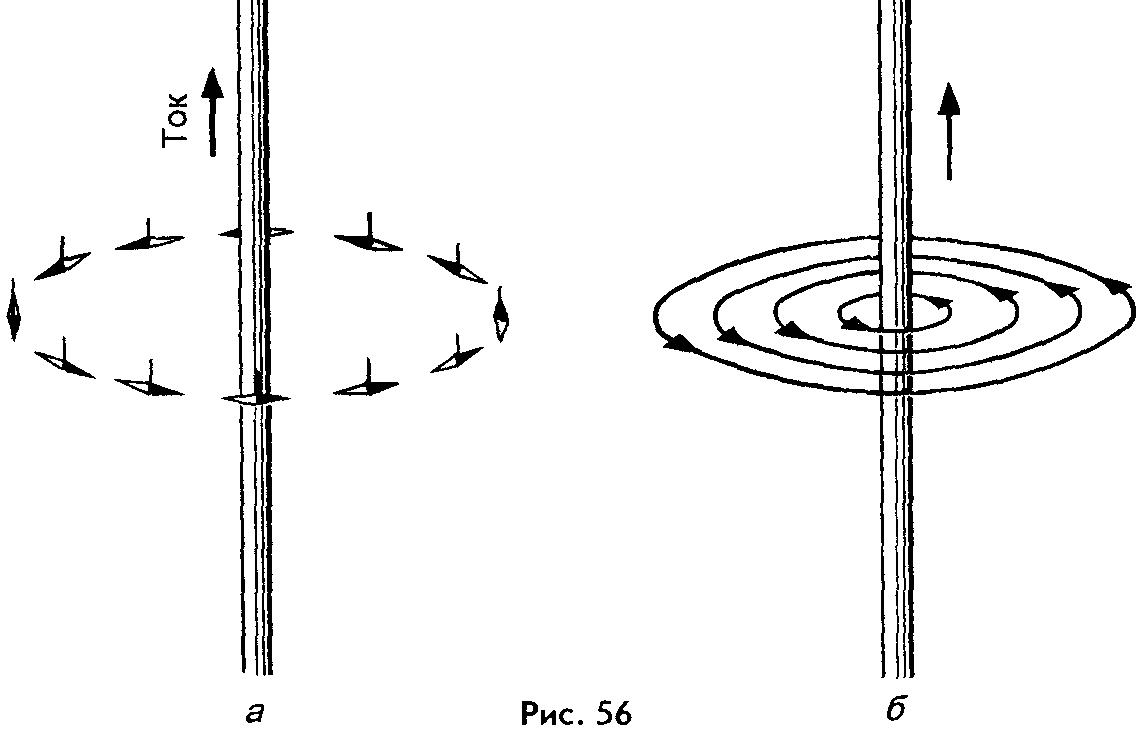
When the direction of the current in the conductor changes, the orientation of the magnetic needles also changes. It means that direction field lines of the magnetic field is related to the direction of the current in the conductor.
The direction of the lines of force of the magnetic field of the rectilinear current is determined using first right hand rule:
if you grasp the conductor with the palm of your right hand, pointing the thumb aside along the current, then the remaining fingers of this hand will indicate the direction of the magnetic field lines of this current(Fig. 57).

???
1. Describe an experiment in which the action of an electric current on a magnetic needle is observed. Who and when was the first to implement it?
2. What is the source of the magnetic field?
3. How are magnetic needles located in a direct current magnetic field?
4. What are called magnetic lines of force?
5. What shape do the lines of force of the magnetic field of a rectilinear current have?
6. Formulate the first rule of the right hand.
If you have corrections or suggestions for this lesson,
The magnetic field of a current-carrying conductor. When current passes through a straight conductor, a magnetic field arises around it (Fig. 38). The magnetic lines of force of this field are arranged along concentric circles, in the center of which there is a current-carrying conductor.
The direction of the magnetic field around a conductor with current is always in strict accordance with the direction of the current passing through the conductor. The direction of the magnetic field lines can be determined according to the gimlet's rule. It is formulated as follows. If forward movement gimlet / (Fig. 39, A) match with current direction 2 in explorer 3, then the rotation of its handle will indicate the direction of the lines of force 4 magnetic field around the conductor. For example, if the current passes through the conductor in the direction from us beyond the plane of the sheet of the book (Fig. 39, b), then the magnetic field that arises around this conductor is directed clockwise. If the current through the conductor passes in the direction from the plane of the book sheet to us, then the magnetic field around the conductor is directed counterclockwise. How more current passing through the conductor, the stronger the magnetic field around it. When the direction of the current changes, the magnetic field also changes its direction.
As you move away from the conductor, the magnetic lines of force are less frequent. Consequently, the induction of the magnetic field and its intensity decrease. The strength of the magnetic field in the space surrounding the conductor, where G- distance from the considered point to the axis of the conductor.
Maximum tension I, | ax takes place on the outer surface of the conductor / (Fig. 40). Inside the conductor also
a magnetic field arises, but its strength decreases linearly in the direction from the outer surface to the axis (curve 2). The magnetic induction of the field around and inside the conductor changes in the same way as the intensity.
Ways to amplify magnetic fields. To obtain strong magnetic fields at low currents, the number of current-carrying conductors is usually increased and performed in the form of a series of turns; such a device is called winding, or coil.
With a conductor bent in the form of a coil (Fig. 41, a), the scale fields formed by all sections of this conductor will have the same direction inside the coil. Therefore, the intensity of the magnetic field inside the coil will be greater than around the rectilinear conductor. When the turns are combined into a coil, the magnetic fields created by the individual turns add up (Fig. 41.6) and their lines of force are connected into a common magnetic flux. In this case, the concentration of field lines inside the coil increases, i.e., the magnetic field inside it increases. The more current passing through the coil, and the more turns it has, the stronger the magnetic field created by the coil.
The magnetic field outside the coil also consists of the magnetic fields of individual turns, however, the magnetic lines of force are not so dense, as a result of which the intensity of the magnetic field there is not as great as inside the coil. The magnetic field of a coil circulated by current has the same shape as the field of a rectilinear permanent magnet(see fig. 35, A): magnetic lines of force exit from one end of the coil and enter the other end. Therefore, the coil, streamlined with current, is an artificial electric magnet. Usually, a steel core is inserted inside the coil to enhance the magnetic field; such a device is called electromagnet.
Electromagnets have found extremely wide application in technology. They create the magnetic field necessary for the operation of electrical machines, as well as the electrodynamic forces required for the operation of various electrical measuring instruments and electrical apparatus.
Electromagnets can have an open or closed magnetic circuit (Fig. 42). The polarity of the end of an electromagnet coil can be determined, like the polarity of a permanent magnet, using a magnetic needle. To the north pole, it turns south end. To determine the direction of the magnetic field created by a coil or coil, you can also use the gimlet rule. If you combine the direction of rotation of the handle with the direction of the current in the coil or coil, then the translational movement of the gimlet will indicate the direction of the magnetic field.
The polarity of an electromagnet can also be determined with the help of the right hand. To do this, put your hand on the coil with your palm (Fig. 43) and combine four fingers with the direction of the current in it, while the bent thumb will show the direction of the magnetic field
Magnetic field of electric current
A magnetic field is created not only by natural or artificial ones, but also by a conductor if an electric current passes through it. Therefore, there is a connection between magnetic and electrical phenomena.
It is not difficult to make sure that a magnetic field is formed around the conductor through which the current passes. Above the movable magnetic needle, place a straight conductor parallel to it and pass an electric current through it. The arrow will take a position perpendicular to the conductor.
What forces could make the magnetic needle turn? Obviously, the strength of the magnetic field that has arisen around the conductor. Turn off the current, and the magnetic needle will return to its normal position. This suggests that with the current turned off, the magnetic field of the conductor also disappeared.
Thus, the electric current passing through the conductor creates a magnetic field. To find out in which direction the magnetic needle will deviate, apply the right hand rule. If the right hand is placed over the conductor with the palm down so that the direction of the current coincides with the direction of the fingers, then the bent thumb will show the direction of deviation of the north pole of the magnetic needle placed under the conductor. Using this rule and knowing the polarity of the arrow, you can also determine the direction of the current in the conductor.
Magnetic field of a straight conductor has the form of concentric circles. If you place your right hand over the conductor with your palm down so that the current seems to come out of your fingers, then the bent thumb will point to the north pole of the magnetic needle.Such a field is called a circular magnetic field.
The direction of the lines of force of a circular field depends on in the conductor and is determined by the so-called "Gimlet" rule. If the gimlet is mentally screwed in the direction of the current, then the direction of rotation of its handle will coincide with the direction of the magnetic field lines of force. Applying this rule, you can find out the direction of the current in the conductor, if you know the direction of the field lines of the field created by this current.
Returning to the experiment with the magnetic needle, we can make sure that it is always located with its northern end in the direction of the magnetic field lines.
So, A straight conductor carrying an electric current creates a magnetic field around it. It has the form of concentric circles and is called a circular magnetic field.
Pickles e. Solenoid magnetic field
A magnetic field arises around any conductor, regardless of its shape, provided that an electric current passes through the conductor.
In electrical engineering, we are dealing with, consisting of a number of turns. To study the magnetic field of the coil of interest to us, we first consider what shape the magnetic field of one turn has.
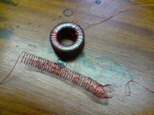
Imagine a coil of thick wire penetrating a sheet of cardboard and connected to a current source. When an electric current passes through a coil, a circular magnetic field is formed around each individual part of the coil. According to the “gimlet” rule, it is easy to determine that the magnetic lines of force inside the coil have the same direction (toward or away from us, depending on the direction of the current in the coil), and they exit from one side of the coil and enter the other side. A series of such coils, having the shape of a spiral, is the so-called solenoid (coil).
Around the solenoid, when a current passes through it, a magnetic field is formed. It is obtained by adding the magnetic fields of each coil and resembles the magnetic field of a rectilinear magnet in shape. The lines of force of the magnetic field of the solenoid, as well as in a rectilinear magnet, exit from one end of the solenoid and return to the other. Inside the solenoid, they have the same direction. Thus, the ends of the solenoid have polarity. The end from which the lines of force come out is north pole solenoid, and the end into which the lines of force enter is its south pole.
Solenoid poles can be determined by right hand rule, but for this you need to know the direction of the current in its turns. If you put your right hand on the solenoid with the palm down, so that the current would seem to come out of the fingers, then the bent thumb will point to the north pole of the solenoid. From this rule it follows that the polarity of the solenoid depends on the direction of the current in it. It is easy to verify this in practice by bringing a magnetic needle to one of the poles of the solenoid and then changing the direction of the current in the solenoid. The arrow will instantly turn 180°, i.e., it will indicate that the poles of the solenoid have changed.
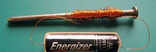
The solenoid has the property of drawing light iron objects into itself. If a steel bar is placed inside the solenoid, then after a while, under the influence of the magnetic field of the solenoid, the bar will become magnetized. This method is used in the manufacture.
Electromagnets
It is a coil (solenoid) with an iron core placed inside it. The shapes and sizes of electromagnets are varied, however general device all of them the same.
The electromagnet coil is a frame, most often made of pressboard or fiber and having various forms depending on the purpose of the electromagnet. A copper insulated wire is wound on the frame in several layers - the winding of an electromagnet. It has a different number of turns and is made of wire of different diameters, depending on the purpose of the electromagnet.
To protect the winding insulation from mechanical damage the winding is covered with one or more layers of paper or some other insulating material. The beginning and end of the winding is brought out and connected to the output terminals mounted on the frame, or to flexible conductors with lugs at the ends.
 The electromagnet coil is mounted on a core made of soft, annealed iron or iron alloys with silicon, nickel, etc. Such iron has the least residual. Cores are most often made composite of thin sheets, isolated friend from friend. The shape of the cores can be different, depending on the purpose of the electromagnet.
If an electric current is passed through the winding of an electromagnet, then a magnetic field is formed around the winding, which magnetizes the core. Since the core is made of soft iron, it will be magnetized instantly. If the current is then turned off, the magnetic properties of the core will also quickly disappear, and it will cease to be a magnet. The poles of an electromagnet, like a solenoid, are determined by the right hand rule. If the electromagnet winding is changed, then the polarity of the electromagnet will change accordingly.
The action of an electromagnet is similar to that of a permanent magnet. However, between them there a big difference. A permanent magnet always has magnetic properties, and an electromagnet only when an electric current passes through its winding.
In addition, the attractive force of a permanent magnet is unchanged, since the magnetic flux of a permanent magnet is unchanged. The force of attraction of an electromagnet is not a constant value. The same electromagnet can have different attractive forces. The force of attraction of any magnet depends on the magnitude of its magnetic flux.

The force of attraction, and hence its magnetic flux, depends on the magnitude of the current passing through the winding of this electromagnet. The greater the current, the greater the force of attraction of the electromagnet, and, conversely, the smaller the current in the winding of the electromagnet, the less force it attracts magnetic bodies to itself.
But for electromagnets of various design and size, the force of their attraction depends not only on the magnitude of the current in the winding. If, for example, we take two electromagnets of the same device and dimensions, but one with a small number of winding turns, and the other with a much larger number, then it is easy to see that with the same current the attractive force of the latter will be much greater. Indeed, the greater the number of turns of the winding, the greater at a given current a magnetic field is created around this winding, since it is composed of the magnetic fields of each turn. This means that the magnetic flux of the electromagnet, and hence the force of its attraction, will be the greater, the greater the number of turns the winding has.
There is another reason that affects the magnitude of the magnetic flux of an electromagnet. This is the quality of his magnetic circuit. A magnetic circuit is a path along which a magnetic flux closes. The magnetic circuit has a certain magnetic resistance. Magnetic resistance depends on the magnetic permeability of the medium through which the magnetic flux passes. The greater the magnetic permeability of this medium, the lower its magnetic resistance.
 Since m the magnetic permeability of ferromagnetic bodies (iron, steel) is many times greater than the magnetic permeability of air, therefore it is more profitable to make electromagnets so that their magnetic circuit does not contain air sections. The product of the current and the number of turns in the winding of an electromagnet is called magnetomotive force. The magnetomotive force is measured by the number of ampere turns.
For example, the winding of an electromagnet having 1200 turns carries a current of 50 mA. Magnetic motive force such an electromagnet equals 0.05 x 1200 = 60 ampere turns.
The action of the magnetomotive force is similar to the action electromotive force V electrical circuit. Just as EMF causes an electric current, the magnetomotive force creates a magnetic flux in an electromagnet. Just as in an electric circuit, with an increase in EMF, the current in the price increases, so in a magnetic circuit, with an increase in the magnetomotive force, the magnetic flux increases.
Action magnetic resistance similar to the action of the electrical resistance of the circuit. As the current decreases with an increase in the resistance of an electric circuit, so in a magnetic circuit an increase in magnetic resistance causes a decrease in magnetic flux.
The dependence of the magnetic flux of an electromagnet on the magnetomotive force and its magnetic resistance can be expressed by a formula similar to Ohm's law formula: magnetomotive force \u003d (magnetic flux / magnetic resistance)
The magnetic flux is equal to the magnetomotive force divided by the magnetic resistance.
The number of turns of the winding and the magnetic resistance for each electromagnet is a constant value. Therefore, the magnetic flux of a given electromagnet changes only with a change in the current passing through the winding. Since the force of attraction of an electromagnet is determined by its magnetic flux, in order to increase (or decrease) the force of attraction of an electromagnet, it is necessary to increase (or decrease) the current in its winding accordingly.
polarized electromagnet
A polarized electromagnet is a combination of a permanent magnet and an electromagnet. It is arranged in such a way. So-called soft iron pole extensions are attached to the poles of the permanent magnet. Each pole extension serves as the core of an electromagnet; a coil with a winding is mounted on it. Both windings are connected in series.
Since the pole extensions are directly attached to the poles of a permanent magnet, they have magnetic properties even in the absence of current in the windings; at the same time, their attraction force is unchanged and is determined by the magnetic flux of a permanent magnet.
The action of a polarized electromagnet is that when current passes through its windings, the force of attraction of its poles increases or decreases depending on the magnitude and direction of the current in the windings. On this property of a polarized electromagnet, the action of other electrical devices.
The action of a magnetic field on a current-carrying conductor
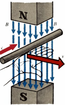
If a conductor is placed in a magnetic field so that it is perpendicular to the lines of force of the field, and an electric current is passed through this conductor, then the conductor will begin to move and will be pushed out of the magnetic field.
As a result of the interaction of the magnetic field with electric shock the conductor is set in motion, i.e., electrical energy is converted into mechanical energy.
The force with which the conductor is pushed out of the magnetic field depends on the magnitude of the magnetic flux of the magnet, the current strength in the conductor and the length of that part of the conductor that the field lines cross. The direction of this force, i.e. the direction of movement of the conductor, depends on the direction of the current in the conductor and is determined by left hand rule.
If you hold the palm of your left hand so that it includes the magnetic field lines, and the outstretched four fingers are facing the direction of the current in the conductor, then the bent thumb will indicate the direction of movement of the conductor. When applying this rule, we must remember that the field lines come out of the north pole of the magnet.
An electric current flowing through a conductor creates a magnetic field around this conductor (Fig. 7.1). The direction of the emerging magnetic field is determined by the direction of the current.
The way to designate the direction of the electric current in the conductor is shown in fig. 7.2: dot in fig. 7.2(a) can be thought of as the tip of the arrow indicating the direction of the current towards the observer, and the cross as the tail of the arrow indicating the direction of the current away from the observer.
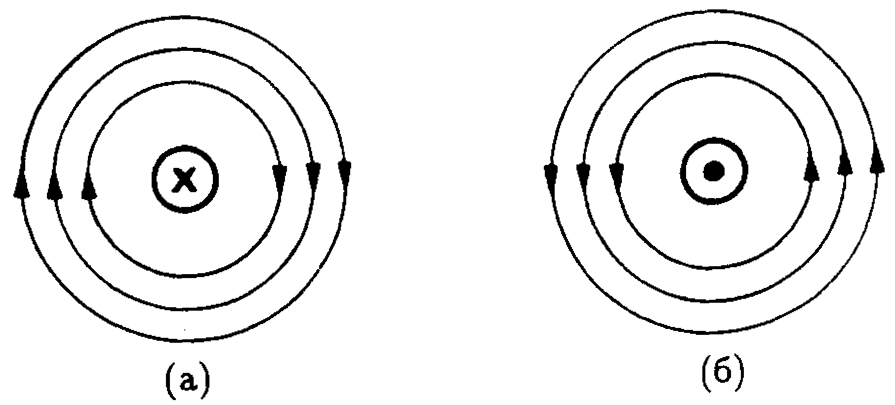
The magnetic field that arises around a current-carrying conductor is shown in fig. 7.3. The direction of this field is easily determined using the rule of the right screw (or the gimlet rule): if the tip of the gimlet is aligned with the direction of the current, then when it is screwed in, the direction of rotation of the handle will coincide with the direction of the magnetic field.
Rice. 7.1. Magnetic field around a current carrying conductor.
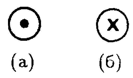
Rice. 7.2. The designation of the current direction is (a) towards the observer and (b) away from the observer.
Field generated by two parallel conductors
1. The directions of the currents in the conductors are the same. On fig. 7.4(a) shows two parallel conductors spaced apart, with the magnetic field of each conductor shown separately. In the gap between the conductors, the magnetic fields they create are opposite in direction and cancel each other out. The resulting magnetic field is shown in fig. 7.4(b). If you change the direction of both currents to the opposite, then the direction of the resulting magnetic field will also change to the opposite (Fig. 7.4 (b)).

Rice. 7.4. Two conductors with the same current directions (a) and their resulting magnetic field (6, c).
2. Directions of currents in conductors are opposite. On fig. 7.5(a) shows the magnetic fields for each conductor separately. In this case, in the gap between the conductors, their fields are summed up and here the resulting field (Fig. 7.5 (b)) is maximum.
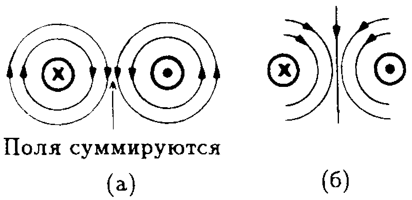
Rice. 7.5. Two conductors with opposite current directions (a) and their resulting magnetic field (b).
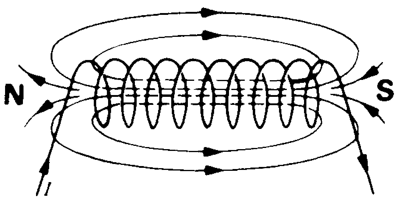
Rice. 7.6. The magnetic field of the solenoid.
The solenoid is a cylindrical coil consisting of a large number of turns of wire (Fig. 7.6). When current flows through the coils of the solenoid, the solenoid behaves like a bar magnet with north and south poles. The magnetic polo he creates is no different from the zero of a permanent magnet. The magnetic field inside the solenoid can be increased by winding the coil around a magnetic core made of steel, iron, or other magnetic material. The strength (value) of the magnetic field of the solenoid also depends on the strength of the transmitted electric current and the number of turns.
Electromagnet
The solenoid can be used as an electromagnet, while the core is made of a magnetically soft material, such as malleable iron. The solenoid behaves like a magnet only when an electric current flows through the coil. Electromagnets are used in electric bells and relays.
Conductor in a magnetic field
On fig. 7.7 shows a current-carrying conductor placed in a magnetic field. It can be seen that the magnetic field of this conductor is added to the magnetic field of the permanent magnet in the area above the conductor and subtracted in the area below the conductor. Thus, a stronger magnetic field is above the conductor, and a weaker one is below (Fig. 7.8).
If you change the direction of the current in the conductor to the opposite, then the shape of the magnetic field will remain the same, but its magnitude will be greater under the conductor.
Magnetic field, current and motion
If a conductor with current is placed in a magnetic field, then a force will act on it, which tries to move the conductor from a region of a stronger field to a region of a weaker one, as shown in Fig. 7.8. The direction of this force depends on the direction of the current as well as the direction of the magnetic field.

Rice. 7.7. Conductor with current in a magnetic field.

Rice. 7.8. Result field
The magnitude of the force acting on a conductor with current is determined by both the magnitude of the magnetic field and the strength of the boom flowing through this conductor.
The movement of a conductor placed in a magnetic field when a current is passed through it is called the motor principle. The operation of electric motors, magnetoelectric measuring instruments with a moving coil and other devices is based on this principle. If a conductor is moved in a magnetic field, a current is generated in it. This phenomenon is called the generator principle. This principle is based on the operation of generators of constant and alternating current.
Until now, we have considered a magnetic field associated only with a direct electric current. In this case, the direction of the magnetic field is unchanged and is determined by the direction of the permanent dock. When an alternating current flows, an alternating magnetic field is created. If a separate coil is placed in this alternating field, then an EMF (voltage) will be induced (induced) in it. Or if two separate coils are placed in close proximity to each other, as shown in fig. 7.9. and apply an alternating voltage to one winding (W1), then a new alternating voltage (induced EMF) will appear between the terminals of the second winding (W2). This is the working principle of a transformer..
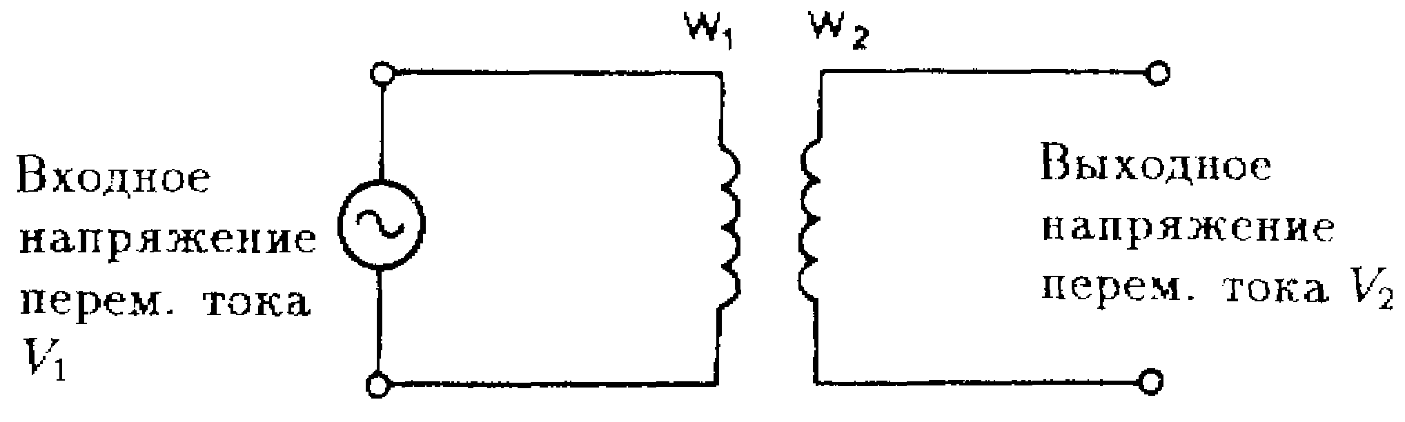
Rice. 7.9. induced emf.
This video talks about the concept of magnetism and electromagnetism:


