OBD diagnostic socket
In this article, I will try to introduce you to the principles of operation of an injection engine from the side of electrical circuits. There is an opinion that the carburetor is simple, reliable and unpretentious, and the injector ... There is no better way "Injector ...". My personal opinion is not necessary to listen to such experts. You just need to figure out the issue.
In order to understand how the car "breathes" there is a diagnostic connector. The form that it now has did not appear immediately. As always, America helped us in this. We know that they are mad with fat, but the fact that something worthwhile comes out of this is a rather rare case. However, in order. For a very long time, the US government supported its auto industry (not to be confused with what is happening in Russia). But then environmentalists sounded the alarm, the very ones that are against warming up cars, they say, spoil the nature of your cars. Commissions, committees and subcommittees, decrees began to be created ... the producers pretended to obey, but in fact they neglected everything that was possible. And then the energy crisis struck, which led to a decline in production, automakers became thoughtful, it became unprofitable to ignore government decisions. It was in such a difficult environment that OBD (On Board Diagnostics) rules were created. www.obdii.com for those who cut in English). Each manufacturer used their own emission control methods. The Association of Automotive Engineers proposed several standards to change this, and the birth of OBD is believed to have occurred when the Department of Air Control made many of these standards mandatory in California for vehicles since 1988. Only a few parameters were monitored: an oxygen sensor, an exhaust recirculation system, a fuel supply system and an engine control unit in terms of exceeding exhaust gas standards. But it was not possible to restore order in this way, but only everything got more confused. Firstly, monitoring systems were literally far-fetched to old cars, since they were created as additional equipment. Manufacturers only formally fulfilled the requirements, the cost of the car increased. Secondly, independent services howled - each car became almost unique, it required detailed instructions from the manufacturer, a description of the codes, a scanner with its own connector. The US government was to blame, it was blamed by manufacturers, environmentalists, service stations, motorists. In 1996, it was decided that all car manufacturers selling their products in the United States must adhere to OBDII, a revised OBD specification. Thus, OBDII is not an engine management system, as many believe, but a set of rules and requirements that every manufacturer must comply with in order to comply with US federal regulations on composition. exhaust gases. For a deeper understanding, I propose to consider in more detail the main requirements of the standard.
1. Diagnostic connector of the OBDII standard. Its main function is to allow the diagnostic scanner to communicate with OBDII-compliant control units and comply with SAE J1962 standards, i.e. it must be located in one of the eight locations defined by the Environmental Protection Agency (wow!!!) and within 16 inches from the steering column. Each contact has its own purpose, some, for example, are left to the discretion of the manufacturer, the main thing is that they do not intersect with OBDII-compatible control units.
Let's take a closer look at connectors. Connectors 4, 5, 16 refer to power, this is done for convenience reasons - the scanner is immediately supplied with power, no separate wire is required, for example, to the cigarette lighter. 2, 10, 6, 14, 7.15 are the actual conclusions of three equivalent standards. Manufacturers can choose which one to use for their products. Thus, in terms of connector and protocols, there is complete unification.
Fig2 
Thus Hyundai disposed of the diagnostic connector. Please note that the numbers of the connectors in the pictures do not match, because the block and the plug are shown.
2. Standard communication protocols for diagnostics. As you can see, the standard provides for only three protocols. The operation algorithm is simple "request - response". The protocols themselves are also classified according to the speed of data exchange.
A- the slowest 10 KB/s. The ISO9141 standard uses a Class A protocol.
B- speed 100 kb/s. This is the SAE J1850 standard.
WITH- speed 1 MB/s. The most used class C standard for vehicles is the CAN protocol.
Let's take a look at these protocols.
J1850 protocol. There are two types: J1850 PWM((Pulse Width Modulation - pulse width modulation) high-speed, providing 41.6 Kbytes / sec. It is used by Ford, Jaguar and Mazda. In accordance with the PWM protocol, signals are transmitted on two wires to pins 2 and 10. J1850 VPW (Variable Pulse Width- variable pulse width) supports data transfer at a rate of 10.4. KB/sec It is used by General Motors (GM) and Chrysler. This protocol uses one wire and uses connector 2. ISO 9141 not as complicated as J1850, does not require communication microprocessors. It is used in most European and Asian vehicles, as well as in some Chrysler models.
Here I want to make a small digression for the owners Hyundai cars. Please note that we have 2 contact involved (protocol ISO 9141), nothing more than the well-known K-Line. And this opens up wide opportunities for the use of BC made for VAZ cars. After all, what the creators of OBDII sought was compatibility, here you get it. There is one nuance, but about it a little later.
3. Check Engine Malfunction Indicator Lamp. It illuminates when the engine management system detects an exhaust gas problem. Its purpose is to inform the driver that a problem has occurred during the operation of the engine control system. It should be interpreted as follows “it would be nice to go to the service” and that's it. The engine won't explode, the car won't catch fire. Another thing is if your oil light or engine overheat warning lights up. Then you need to panic. The Check Engine light comes on according to a certain algorithm, depending on the severity of the malfunction. If the malfunction is serious and urgent repair is required, the indicator lights up immediately. Such a malfunction belongs to the category of active (Active). If the error is not fatal, the indicator is off, and the fault is assigned a stored status (Stored). In order for such a fault to become active, it must repeat itself for several drive cycles (this is the process by which a cold engine starts and runs until it reaches operating temperature).
4. Diagnostic error codes (DTC - Diagnostic Trouble Code). A malfunction in the OBDII standard in accordance with the J2012 specification is described as follows:
rice3 
First character Indicates which part of the vehicle has a problem. The choice of symbol is determined by the diagnosed control unit. If a response is received from two blocks, the letter for the block with the higher priority is used.
P- engine and transmission
B- body
C- chassis
U- network communications
The second character shows what the code defined.
0 or P0- basic (open) fault code defined by the Association of Automotive Engineers.
1 or P1- a fault code determined by the vehicle manufacturer.
But not everything is as smooth in the Kingdom of Denmark as it seems at first glance. Remember, I promised to tell about one nuance. So, almost all BCs know P0 codes - basic ones, but internal codes for each car are different. For example, Accent has its own unique error codes for each model year, but on Matrix - no, why this happened is a mystery to me.
The third character is the system in which the fault has been detected. It carries the most useful information.
1 - fuel-air system
2 - fuel system
3 - ignition system
4 - auxiliary emission control system (exhaust gas recirculation valve, engine exhaust air intake system, catalytic converter or ventilation system fuel tank)
5 - speed control system or idling with appropriate auxiliary systems
6 - engine control module
7
8 - transmission or drive axle
Fourth and fifth characters this is an individual error code. They usually correspond to old OBDI codes.
5. Self-diagnosis of malfunctions leading to increased toxicity of emissions. Engine Management Software is a set of OBDII compliant programs that run in the engine control unit and "watch" everything that happens around. The engine control unit is a real computer. During the operation of which a huge number of calculations are performed for commands by numerous engine devices, based on data received from various sensors. In addition to this, the controller must carry out diagnostics and control of the components of the OBDII system, namely:
Check drive cycles that determine the generation of error codes
Starts and executes component monitors
Specifies the priority of monitors
Updates the readiness status of monitors
Displays test results for monitors
Does not allow conflicts between monitors
The monitor is a test performed by the OBDII system in the engine control unit to evaluate the correct functioning of the emission components. There are two types of monitors:
Continuous (performs as long as there are appropriate conditions)
Discrete (triggered once per trip)
There remains one more issue that needs to be considered separately - these are on-board computers (BC). Just don't confuse it with Amigo crafts or regular ones - they practically do not carry any useful information. What are real BCs for and what can they do? There are a lot of people who just like to dig with their car, to know how it “lives”. Sometimes you can just save money - for example, he himself determined which sensor was out of order, buy it himself, change it himself. After all, the service center will definitely include diagnostics in the bill, and the sensor will sell with an unimaginable markup. For example, I very often come to the service with a ready-made solution - I'm interested in solving the problem, but turning the nuts is not. I'm wondering what the instantaneous consumption is, how the mains voltage jumps from consumers, what parameters are given by the sensors, what errors in operation were recorded. It's a hobby. And I understand perfectly why manufacturers not only do not install full-fledged BCs, but also do not certify from third-party manufacturers. We deprive dealers of super profits. The formal pretext is an extra load on the engine control unit, they say it is forced to process more BC requests. Of course, there is logic in such a statement, but excuse me, but dealers have scanners that don’t load? Load, but they are certified. And they cost incredible money. Some vicious circle. In general, draw your own conclusions. I hope that with the help of this article you have come closer to understanding your car.
A modern car is saturated with various electronic systems, one of which is the on-board equipment diagnostic system. When building similar system it uses an obd2 connector, standardized in 1996 and most often used to connect a scanner. It can also be involved in the analysis of such current parameters as voltage, temperature, speed and similar ones, including directly during the current operation of the car.
Appearance Obd2
According to requirements normative documents the obd2 connector socket is located in the passenger compartment next to the steering wheel (at least 18 cm distance). Electrical characteristics connectors are sufficient to organize information exchange using the digital industrial CAN bus ( maximum amount nodes - 32, the maximum length of the cable - 35 m).
Connector design
The obd2 connector, from a mechanical point of view, realizes a two-piece single-ended constructive scheme and contains 16 contacts, which are arranged in two rows. The numbering of contacts in the socket is made from left to right, with the top row numbered from 1 to 8, and the bottom row from 9 to 16. The plug and socket bodies are made of plastic, to increase operational reliability a thin separator plate is provided in the socket between the rows of contacts.
To automatically set the correct polarity when connecting, the plug and socket housings are trapezoidal in cross-section with rounded corners.
The connector contacts form two groups according to their purpose. The first of them is standardized, the contacts of the second group can be used by each manufacturer to solve their problems.

Numbering and assignment of pins obd2 connector
pinout obd2 connector indicating the purpose of individual contacts is given in the table.
| 1 | Branded |
| 2 | Bus J1850 |
| 3 | Branded |
| 4 | Grounding general |
| 5 | signal ground |
| 6 | CAN bus |
| 7 | Line K according to ISO 9141-2 |
| 8 | Branded |
| 9 | Branded |
| 10 | Bus J1850 |
| 11 | Branded |
| 12 | Branded |
| 13 | Branded |
| 14 | CAN bus |
| 15 | Line L according to ISO 9141-2 |
| 16 | +12V |
Independent production of a connecting cable
Necessity self-manufacturing or repair connection cable may occur when connecting the diagnostic tool to the vehicle's on-board computer network. To do this, use the data given in the table. The wires of the cable are connected to the contacts of the plug and socket by soldering in compliance with the usual rules in such cases. After soldering, the contact can be additionally protected with a short cambric.
With the time of appearance in cars electronic systems control from microprocessors, it also became necessary to check the operation parameters of the blocks themselves and the connecting electrical circuits. For this purpose, they invented equipment called (On Board Diagnostic), initially it only gave out information about the malfunction, without any clarification.
IN modern cars using the OBD connector with the standard pinout of the connector for diagnostics to on-board computer you can connect a special or scanner and conduct complete diagnostics independently to almost any motorist. Since 1996, the second concept of the standard has been developed in the USA, which has become mandatory for newly produced cars.
Purpose of OBD2 determine:
type of diagnostic connector;
pinout of the connector for diagnostics;
electrical communication protocols;
message format.
The European Union has adopted EOBD, which is based on OBD2. It has been mandatory for all cars since January 2001. OBD-2 supports 5 communication protocols.
Knowing the location and standard pinout of the connector, you can check the car yourself. Thanks to the widespread implementation of OBD2 when diagnosing a car, you can get an error code that will be the same regardless of the make and model of the car.
The standard code contains the X1234 structure, where each character carries its own meaning:
X is the only alphabetic character that allows you to recognize faulty system(engine, gearbox, electronic components, etc.);
1 - represents the general code of the OBD2 standard or additional factory codes;
2 - clarification of the location of the malfunction (power or ignition system, auxiliary circuits, etc.);
34 - sequence number of the error.
The pinout of the OBD2 diagnostic connector has a special power plug from onboard network, this allows you to use any scanners and adapters without additional electrical circuits. If earlier diagnostic protocols showed only general information about the presence of any problem, now, thanks to the connection of the diagnostic device with the electronic components of the car, it can be considered more full information about a specific problem.
Each connected diagnostic equipment must comply with one of three international standards:
The location of the diagnostic connector with OBD2 pinout for diagnostics can vary greatly in various cars. There is no single standard for location, the car manual or sleight of hand will help you here.
Below are a few common points for your convenience:
- in the slot of the lower casing of the instrument panel in the region of the left knee of the driver;
- under the ashtray installed in the central part of the instrument panel (some Peugeot models);
- under plastic plugs on the bottom of the instrument panel or on the center console (typical for VAG products);
- on the back wall of the instrument panel behind the glove box housing (some Lada models);
- on the center console near the lever parking brake(found on some machines
- at the bottom of the armrest niche (common on French cars);
- under the hood near the motor shield (typical for some cars of Korean and Japanese production).
Many motorists also sometimes intentionally transfer the OBD2 pinout connector to another not always standard place, this may be due to repairing electrical wiring or protecting the car from theft.
Types of connectors with pinout OBD2
In the early 2000s, there were no strict requirements for the external shape of the connector, and many car manufacturers independently assigned the configuration of the device. There are currently two types of OBD 2 connector, referred to as Type A and Type B.
Both plugs are almost identical in appearance and have a 16-pin output (two rows of eight pins), the only difference is between the central guide grooves.
The numbering of the pins in the block is from left to right, while in the top row there are contacts with numbers 1-8, and in the bottom row - from 9 to 16. The outer part of the case is made in the shape of a trapezoid with rounded corners, which ensures reliable connection of the diagnostic adapter. The photo shows both devices.

Connector options - Type A on the left and Type B on the right
OBD 2 connector - pinout
Below is a diagram and pin assignment in the OBD2 pinout connector, which are defined by the standard.

Numbering of plugs in the connector
General description of plugs:
1 - reserved, this pin can output any signal that is set by the car manufacturer;
2 - channel "K" for transmitting various parameters (may be designated - bus J1850);
3 - similar to the first;
4 - grounding of the connector on the car body;
5 - diagnostic adapter signal grounding;
6 - direct connection CAN bus contact J2284;
7 - channel "K" according to ISO 9141-2;
8 - similar to contacts 1 and 3;
9 - similar to contacts 1 and 3;
10 - pin for connecting the bus of the J1850 standard;
11 - pin assignment is set by the vehicle manufacturer;
12 - similarly;
13 - similarly;
14 - additional pin of the CAN bus J2284;
15 - channel "L" according to ISO 9141-2;
16 - positive output of the on-board network voltage (12 Volts).
An example of the factory pinout of the OBD 2 connector is the Hyundai Sonata, where pin 1 receives a signal from the control unit anti-lock braking system, and on pin 13 - a signal from the control unit and sensors inflatable pillows security.
Depending on the operation protocol, pinout options are allowed:
When using the standard ISO 9141-2 protocol, it is activated via pin 7, while pins 2 and 10 in the connector are inactive. For data transfer, pins with numbers 4, 5, 7 and 16 are used (sometimes pin number 15 can be used).
With a protocol like SAE J1850 in the VPW (Variable Pulse Width Modulation) version, pins 2, 4, 5, and 16 are used. The connector is typical for American and European cars General Motors.
The use of the J1850 in PWM (Pulse Width Modulation) mode provides for the additional activation of pin 10. This type of connector is used on products concern Ford. It is common for the J1850 protocol in any form not to use pin number 7. Beginning of form
Of course, for many, such diagrams and descriptions of the pinouts of the OBD2 connector are very complex and unnatural. Often, motorists prefer to periodically give their car to a specialized car service and not even think about diagnostic connectors and, moreover, about their pinouts. But still it is worth recognizing the usefulness self diagnosis. Experienced motorists say that every car owner needs to have a diagnostic scanner in the car to quickly check their doubts about the operation of the car, check for errors, settings, and the like, which, first of all, will save a lot of money.
Obvious advantages of self-diagnosis via OBD2 connector:
- Cost savings, service stations charge a lot of money for simple computer diagnostics
- Quickly find out the error and understand the malfunction without the help of specialists, you do not need to be nervous in the service station and you can avoid invented breakdowns, as is often the case in unscrupulous services.
Good luck on the road and in car diagnostics!
This has probably happened to each of us: you are driving in your car and suddenly the yellow “Check Engine” light on the dashboard lights up as an alarm that there is some kind of engine problem. Unfortunately, this alone doesn't give any clue as to what exactly is causing the problem and can mean anything from a leaky fuel cap to problems with the catalytic converter. I remember a '94 Honda Integra had an ECU under the driver's seat and a red LED would flash if there was any problem with the engine.
By counting the number of "blinks", it was possible to determine the error code. As car ECUs become more and more complex, the number of error codes increases exponentially. Usage on-board diagnostics Vehicle On-Board Diagnostic (OBD-II) solves this problem. This adapter allows you to use a personal computer for OBD diagnostics. The AllPro adapter is functionally compatible with ELM327 and supports all existing OBD-II communication protocols:
ISO 9141-2
ISO 14230-4 (KWP2000)
SAE PWM J1850 (Pulse Width Modulation)
SAE VPW J1850 (Variable Pulse Width)
ISO 15765-4 Controlled Area Network (CAN)
VPW, PWM and CAN
The first two ISO protocols are described in the previous publication cited above. detailed OBD description protocols is beyond the scope of this article, I will only list them briefly. J1850 VPW (Variable Pulse Width) is a protocol for General Motors cars and some Chrysler models with a transmission rate of 10.4 kbps over a single wire.
The voltage on the VPW bus varies from 0 to 8 V, data is transmitted over the bus in alternating short (64 µs) and long (128 µs) pulses. The actual data transfer rate on the bus varies depending on the data bit mask and ranges from 976 to 1953 bytes/s. This is the slowest of the OBD protocols.
J1850 PWM(Pulse With Modulation) is used in Ford vehicles. The baud rate here is 41.6 kbps using a differential signal over two wires. The bus voltage changes from 0 to 5 V, and the pulse duration is 24 µs. Working with this protocol requires accuracy in programming the microprocessor, since the speed of executing instructions of the "C" language on a PIC microprocessor, even with an improved PIC18 architecture, becomes comparable to the length of a short PWM protocol packet (7 μs).
CAN(Controlled Area Network) protocol developed by Robert Bosch in 1983 and finally standardized in ISO 11898. Using CAN data bus in the car allows various devices communicate with each other, bypassing the central processor, the so-called multi-master mode.
The advantages are also increased transmission speed, up to 1 Mbps and better noise immunity. The protocol was originally intended for use in cars, but is now being used in other areas. To improve the reliability of data transmission, CAN buses use a two-wire differential signal transmission method. The wires that form this pair are called CAN_High and CAN_Low.
In the initial state of the bus on both wires, constant pressure at a certain base level, approximately 2.5 V, called the recessive state. When switching to the active (dominant) state, the voltage on the CAN_High wire increases, and on the CAN_Low wire it decreases, Fig.1.

There are also two message or frame formats - standard with 11 bit address field (CAN 2.0A) and extended with 29 bit field (CAN 2.0B). ISO 15765-4 defines the use of both CAN 2.0A and CAN 2.0B for OBD purposes. Together with bus speeds of 250 and 500 kbps, this creates 4 different CAN protocols.
Does your vehicle support OBD-II?
OBD is mandatory in North America and Europe only. If in America this rule has been in effect since 1996, then the European Union adopted the EOBD auto-diagnostics option based on OBD-II relatively recently. In Europe, OBD has been mandatory since 2001, and for diesel engines even from 2004. If your car was manufactured before 2001, then it may not support OBD at all, even with the appropriate connector.
For example, Renault Kangoo 99 does not support EOBD (although the 2004 editorial Kangoo dcI60 with CAN protocol was successfully docked with the adapter described, and Renault Twingo does! The same cars made for other markets, such as Turkey, may not be OBD compliant either. How determine which protocol is supported by the vehicle's ECU?
First- you can search for information on the Internet, although there is a lot of inaccurate and unverified information. In addition, many vehicles are produced for different markets with different diagnostic protocols. Second more reliable way- find the connector and see what contacts are present in it. The connector is usually located under dashboard from the driver's side. The ISO 914-2 or ISO 14230-4 protocol is defined by the presence of pin 7 as shown in Table 1.

Most cars recent years release only supports CAN protocol with pins 6 and 14 respectively. In Europe and North America, all new vehicles from 2007/2008 must use CAN-only OBD. I note, however, that, as correctly noted in the comment, "If the brand is present in the table, then this does not guarantee OBD-II support."
Use of L-line in ISO 9141/14230… Separately, I would like to say about the L-line in ISO 9141-2 / 14230-4 protocols. Now it is practically not used anywhere, since only the K-line is quite enough for the communication initialization procedure. The standard, however, says that the initialization signal must be transmitted on two lines simultaneously, K and L. Vladimir Gursky from www.wgsoft.de, the author of the ScanMaster ELM program, has collected a large collection of various ECUs.
As an example of the need for an L-line, he cites a 2005 Renault Twingo 1.2L. Using only the K-line for initialization here results in an incorrect engine address in the ECU responses. If initialization is performed on K and L at the same time, then everything works correctly.
Fig 2
AllPro adapter to PIC18F2455
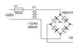
The diagram of my all-protocol OBD-II adapter is shown in fig.2. The basis is the Microchip PIC18F2455 microcontroller, which has a USB interface module. The device uses a 5 V power supply from the USB bus. Capacitor C6 serves as a filter for the internal 3.3V regulator to power the USB bus. LEDs D2 and D3 are receive/transmit indicators, and LED D1 is used to control the status of the USB bus.
The output of the ISO 9141/14230 interface is controlled by half of the IC2-2 driver, and the input signal is fed through the divider R12/R13 to the RX input (pin 18), which is a Schmidt trigger, like most PIC18F2455 inputs, which provides fairly reliable operation. To control the L-line, IC3-1 and R10 are used.
The J1850 VPW bus requires an 8V supply from the L78L08 IC4 regulator. The VPW output is signaled through inverter IC3-2 and buffer FET Q1. The R7/R8 divider and the internal Schmidt trigger at the RA1 input make up the J1850 PWM protocol input interface. The internal comparator (inputs RA0 and RA3) of PIC18F2455 together with resistors R4, R5 extracts the PWM differential signal. IC2-1 and FET Q2 are used to control the output of the PWM bus.
Separately, I want to say about CAN support. Microchip does not release controllers containing both CAN and USB. It is possible to use a controller with a CAN module and an external USB chip such as FT232R. Or vice versa, connect an external CAN controller, as done in this adapter. The CAN interface here is formed by the MCP2515 controller (IC5) and the MPC2551 transceiver (IC6). The MCP2515 is connected via SPI to the PIC18F2455 and is programmed each time the adapter is powered up.
Bus termination RC strings R14/C10 and R15/C11 are designed to reduce reflections on CAN bus according to ISO 15765-4. Their use is not necessary, with a relatively short cable, reflections can be neglected. PIC18F2550 with the same firmware can be used instead of PIC18F2455, see table 2 for replacement options.


table 2
The appearance of the device is shown in Fig.3 and the cover, and the printed circuit board in Fig.4.


Programming PIC18F2455
To program the PIC18, you can use a simple JDM programmer, the diagram is shown in fig.5.
pic 5
It is very simple and could be assembled in an hour on a breadboard. The disadvantage is that the programmer requires a serial (Com) interface in the computer and does not work with virtual USB / Com adapters. The use of laptops is also not recommended, as they do not provide the necessary voltage at the output of the Com port.


pic 6
The programmer's wiring is shown in fig.6 and made using the so-called "stripboard" technology, a fairly popular approach to layout. A typical stripboard has a matrix of 2.54 mm pitch holes for mounting electronic components connected by strips of copper on reverse side, hence the name - stripboard.
By cutting the strips on the reverse side and placing wire jumpers on top, relatively simple structures can be quickly assembled. The strips are easily cut by countersinking holes with a conventional drill. There is even special program- "LochMaster" for designing structures in this way. When using a programmer, please note that the PC case (pin 5 of the DB9 connector) does not match the programmer case.
Another condition is to use a "full" series cable with all the wires necessary for the circuit to work. The programmer works reliably with WinPic , the only problem is that you need to separately download the PIC18F2455.dev (or PIC18F2550.dev) descriptor file from the Microchip IDE distribution after WinPic itself is installed.
Another program that works with the JDM programmer is PICPgm, no additional files are required here, although the author should work on the English grammar, fig.7. Adapter firmware is available.
OBD-II cable
The adapter uses a "standard" DB-9/OBD-II cable to connect to the on-board computer. The cable layout is shown in table 3.

Connecting and testing the device. A correctly assembled adapter does not need to be adjusted and is recognized by Windows as a USB device. The PIC18F2455 microprocessor does not have its own driver and uses the Windows 2000/XP/Vista CDC (Communication Device Class) driver usbser.sys virtual Com port.


Regarding the use of the driver, however, I would like to add that, according to information from www.usb.org, I fixed bugs in usbser.sys only starting with Windows XP SP2 and using the adapter with Windows 2000 can be problematic. After the adapter is recognized as a USB device and the driver is installed, you can start testing.
To do this, you need to connect a stabilized voltage source of 12 volts to pins 1 and 9 of connector J2 and connect the adapter to a personal computer via a USB cable. The presence of 8 V voltage is checked at the output of the regulator IC4. The next step is to run Windows Applications HyperTerm and connecting to the Com port of the adapter.
The device has a self-diagnostic procedure with checking the passage of the signal from the output to the input according to all protocols. To do this, use the command " [email protected]”, Fig.8.


The passage is checked along the following chains:
IC2-1, R4 for negative bus PWM
Q2, D6, R5 for positive bus PWM
IC3-2, IC4, R11, Q1, D5, R7, R8 for VPW
IC2-2, R9, R12, R13 for ISO 9141/14230
MCP2515 controller response via SPI bus
For example, the absence of IC2 will lead to two errors at once, Fig.9.


The self-diagnosis procedure does not include checking the CAN transceiver MCP2551, here you can simply measure the voltage at pins 6 and 7. It should be within 2.5 V.
Working with the Adapter
The adapter is command compatible with the ELM327 and can be used with applications that work with the ELM327. I prefer to use "ScanMaster ELM" by Vladimir Gursky, fig.10.

 ScanTool.net for Windows v1.13
Digimoto
PCMSCAN
EasyObd II Pro
As an example, I will give a situation that happened to my friend's VW Passat. The “Check Engine” light came on in the car, the connection of the ANPro adapter determined the error P0118 - “engine coolant temperature circuit high input”, i.e. high level signal from the coolant temperature sensor, fig. eleven . Further investigation revealed faulty sensor. After replacing the sensor, the error was cleared using the "Clear Trouble codes" button, see fig.12. The error disappeared and did not appear again, fig.13.


Since 1996, it has become necessary to check all cars produced for compliance with OBD standards. This was due to the requirement to control the environmental situation. Short description devices for control, location, functions further in our article.
Brief description of the control device
ATTENTION! Found a completely simple way to reduce fuel consumption! Don't believe? An auto mechanic with 15 years of experience also did not believe until he tried it. And now he saves 35,000 rubles a year on gasoline!
Designation OBD pinout- 2 is used to check compliance with the standard during the diagnosis and control of the operation of car engines and units installed on the chassis. The device is made in the form of a diagnostic connector for connecting devices that monitor exhaust gases and work of the whole car without interruption. The OBD-2 pinout is a set of requirements that all car manufacturers must comply with.
It is required that the connector be located in the passenger compartment at a distance of at least 18 cm from the steering column. The system is universal for all cars, it has a standard CAN digital protocol that allows you to take data at any time. You can make a detailed identification of various problems in the machine.
When diagnosing imported cars, additional lines K - Line and L - Line are used, as well as digital ways transmission of indicators - CAN.

The control function is supported by sixteen contacts:
- contact number one - it is installed at the factory - the manufacturer;
- the second refers to the J 1850 tire;
- number three is also put by the automaker;
- the fourth - to control the grounding contacts of the auto - chassis;
- number five controls the signal line ground network;
- contact number six is responsible for the CAN digital bus;
- number seven - ISO 9141 - 2, K - Line;
- eight and nine installed by the automaker;
- the tenth controls the CANJ 1850 bus;
- numbers eleven, twelve and thirteen are also installed at the car factory;
- pin number fourteen controls the CANJ 2284 bus;
- fifteen - ISO 9141-2, L - Line;
- the sixteenth controls the battery voltage.
OBD adapters - 2 connectors for diagnostics
Cars of all brands in without fail must be equipped with diagnostic OBD adapter– 2. It is used when diagnosing a car independently or in service centers. The adapter is suitable for:
- diagnosing all units of the car;
- analysis of errors and mileage status;
- monitoring the operation of the engine;
- for tension;
- temperature;
- speed;
- condition of panel devices;
- you can track the average and current fuel consumption;
- the degree of heating of the motor;
- control the trips.
You can connect laptops, computers, phones to the adapter. It is suitable for connecting to the OBD - 2 system and all programs that are covered by their OBD 2 pinout requirements. The connection is made with a USB cable, bluetooth or WI-FI. With the help of an adapter, cars of various imported and domestic manufacturers can be tested.
Connector functions provided by OBD-2 pinout
The main function of the OBD - 2 connector is to provide communication between the scanning device and the control units. The pinout provides for automotive power and ground connections for successful work automotive scanner, without connecting a special power supply unit. When choosing a scanner, you should learn about its capabilities. The higher its price, the more accurate the verification will be. If it is not possible to purchase an expensive device, you need to choose a scanner made specifically for this brand car.
Pinout allows the driver to match his car with the block OBD diagnostics – 2.
When a non-compliance with certain exhaust gas composition requirements is detected, the CheckEngine signal will appear, calling for the engine to be checked, and the light will turn on. This is an indicator warning about the amount of harmful gases exceeding the norm.
With the help of the obd 2 system, pinout control is carried out important parameters, the main of which is clean air. The presence of the connector makes it possible to monitor the degree of serviceability of the car without qualified expensive assistance.