When designing amplifier power supplies often there are problems that are in no way connected with the amplifier itself, or are a consequence of the applied element base. So in power supplies transistor amplifiers of high power, it often becomes a problem to implement a smooth switching on of the power supply, that is, to ensure a slow charge of electrolytic capacitors in the smoothing filter, which can have a very significant capacity and, without taking appropriate measures, at the moments of switching on, they will simply disable the rectifier diodes.
In the power supplies of tube amplifiers of any power, it is necessary to provide a delay in the supply high anode voltage before the lamps are warmed up, in order to avoid premature depletion of the cathode and, as a result, a significant reduction in the lamp life. Of course, when using a kenotron rectifier, this problem is solved by itself. But in the case of using a conventional bridge rectifier with an LC filter, you cannot do without an additional device.
Both of the above problems can be solved by a simple device that can be easily built into both a transistor and tube amplifier.
Device diagram.
The schematic diagram of the soft start device is shown in the figure:

Zoom on click
The alternating voltage on the secondary winding of the transformer TP1 is rectified by the diode bridge Br1 and stabilized by the integral stabilizer VR1. Resistor R1 provides a smooth charge of capacitor C3. When the voltage on it reaches the threshold value, the transistor T1 will open, as a result of which the Rel1 relay will operate. Resistor R2 discharges capacitor C3 when the device is turned off.
Inclusion options.
The relay contact group Rel1 is connected depending on the type of amplifier and the organization of the power supply.
For example, to ensure a smooth charge of capacitors in the power supply transistor power amplifier, the presented device can be used to shunt the ballast resistor after the capacitors are charged in order to eliminate power losses on it. A possible inclusion option is shown in the diagram:

The fuse and ballast resistor ratings are not indicated, as they are selected based on the power of the amplifier and the capacitance of the smoothing filter capacitors.
In a tube amplifier, the presented device will help organize a feed delay high anode voltage before the lamps warm up, which can significantly extend their service life. A possible inclusion option is shown in the figure:

The delay circuit here is turned on simultaneously with the filament transformer. After the lamps have warmed up, the Rel1 relay will turn on, as a result of which the mains voltage will be applied to the anode transformer.
If your amplifier uses one transformer both to power the filament circuits of the lamps and for the anode voltage, then the relay contact group should be transferred to the secondary winding circuit anode voltage.
Elements of the turn-on delay circuit (soft start):
- Fuse: 220V 100mA,
- Transformer: any low-power with an output voltage of 12-14V,
- Diode bridge: any small-sized with parameters 35V / 1A and above,
- Capacitors: C1 - 1000uF 35V, C2 - 100nF 63V, C3 - 100uF 25V,
- Resistors: R1 - 220 kOhm, R2 - 120 kOhm,
- Transistor: IRF510,
- Integral Stabilizer: 7809, LM7809, L7809, MC7809 (7812),
- Relay: with winding operating voltage 9V (12V for 7812) and contact group of appropriate power.
Due to the low current consumption, the stabilizer chip and the field effect transistor can be mounted without radiators.
However, someone may have the idea to abandon the extra, albeit small-sized, transformer and power the delay circuit from the filament voltage. Given that the standard heating voltage is ~ 6.3V, you will have to replace the L7809 stabilizer with the L7805 and use a relay with a winding operating voltage of 5V. Such relays usually consume significant current, in which case the microcircuit and transistor will have to be equipped with small heatsinks.
When using a relay with a 12V winding (somehow more common), the integrated stabilizer microcircuit should be replaced with a 7812 (L7812, LM7812, MC7812).
With the values of resistor R1 and capacitor C3 indicated in the diagram delay time inclusion is of the order 20 seconds. To increase the time interval, it is necessary to increase the capacitance of the capacitor C3.
The article was prepared based on the materials of the magazine "AudioXpress"
Free translation of the Editor-in-Chief of Radio Gazeta.
For every diligent owner, it is important that all light bulbs function as far as possible. In order to prolong the use of these lighting fixtures and mitigate significant voltage drops when turning on / off, a soft start device for incandescent lamps, or UPVL, is used.
Many of us have witnessed how the light bulb “bangs” - it burns out when turned on. This happens because too sharp turn-on amplitudes wear out the filament a lot. When idle, the resistance will be quite low. When heated during a normal turning on of the light, a rather high current immediately begins to flow in a spiral, up to 8 amperes. High current when voltage is applied causes the spiral to work at its limit, and the life of the light bulb decreases.
Connection using a protection box
Usually, to solve this problem, a protection unit is used, which performs the function of the UWL. When used with incandescent lamps of this device, the voltage rises when turned on not so sharply, but gradually increases. Thus, the filament does not experience unnecessary overloads, and the life of the bulb increases.
Let us consider in more detail the scheme of operation of this device using the example of a Uniel Upb-200W-BL block connected in series to a 75 W incandescent lamp. In this circuit, the current first passes through the block and only then goes to the lamp. As a result of this, an additional voltage drop occurs, and not the standard 220, but 171 V is supplied to the lamp. Moreover, due to the passage of current through the protection unit, the voltage rises to 171 V smoothly in 2-3 seconds.

Reducing the incoming voltage also helps to increase the life of the light bulb. But, on the other hand, reduced voltage significantly reduces the luminous flux, by about 70 percent, and this is a significant indicator. Therefore, when using a protection unit, it is necessary to take into account the losses in illumination and use more powerful lamps compared to conventional ones.
The block considered in our scheme can withstand power up to 200 W, which means that lamps of approximately the same power can be connected to it. But it is better to set a small margin of 20-25 percent and use lamps with a total power of no more than 160 watts in the circuit. Due to the power reserve, the lamps and the unit itself will last longer. Naturally, the unit itself should not be supplied with a voltage of more than 200 watts.
Note! When the power of the incandescent lamp is lowered, the color temperature changes and the light becomes redder. Changes in the color of lighting can affect the well-being of a person.
The scheme for smoothly turning on incandescent lamps is quite simple. The block is installed in series from the switch to the lamp, that is, into the break of the phase wire.
The block itself can be placed in two places:
- next to the lighting fixture;
- at the switch - in this case, the unit is located in a junction or installation box.

The choice of location depends on the size of the protection unit; for a too large device, you will have to allocate a separate place. The disadvantage of placing it in a socket is that the protection unit will not have sufficient air access for cooling.
Attention! The protection unit cannot be installed in rooms with high humidity.
How to make a protection block yourself
To create a block, you can apply the following scheme.

The device works according to the following principle:
- First, the field effect transistor is closed. Stabilization voltage is applied to it. The lamp does not light;
- When voltage is applied from resistor R1 and diode VD 1, capacitor C1 charges up to 9.1 V. This is the maximum level, which is limited by the parameters of the zener diode;
- When the set voltage is reached, the transistor gradually opens and the current increases. The drain voltage will drop. The filament of the lamp will start to light up smoothly;
- The second resistor controls the degree of discharge of the capacitor. Due to this resistor, the capacitor can continue to discharge even after the power is turned off.
Important! It is necessary to carry out an independent installation of any electrical devices with strict observance of safety regulations.
The use of this protection unit allows not only the smooth start of incandescent lamps, but also to protect them from unpleasant flickering during the operation of the lamp.
Using dimming
Smooth turning on of incandescent lamps can also be done with dimmers or dimmers. The name dimmer comes from the English "dim", which means to darken. Here, the level of voltage supply is regulated automatically or mechanically (due to the rotation of the knob) in a way. For simple dimmers, the control circuit is built on a rheostat - a variable resistor. Now for these purposes, semiconductor triacs or transistor switches are used. In modern electrical engineering, devices with a timer, sensor or remote control are mainly used to smoothly turn on 220 W incandescent lamps. Usually dimmers are installed instead of a regular switch.
Important! When installing a dimmer on incandescent lamps, it is impossible to achieve energy savings. Lowering the light level by 50 percent saves only 15% of electricity.

In rotary dimmers, the incandescence of halogen lamps is adjusted by turning the potentiometer knob. In electronic - all parameters are set automatically.
Additional Information. The dimmer may interfere with sensitive measuring devices and radio receivers. The use of the device sometimes causes additional background when the recording equipment is in operation. All this must be taken into account when installing devices.
You can assemble a simple regulator with your own hands.
The scheme consists of:
- BT134 - 700 V triac, which can be replaced with KU208G, MAC212-8, MAC8S, BT138 or BT136;
- DB3 - dinistor, you can also use KN102, HT40 HT34, HT32, DC34, DB4;
- non-polar capacitor with a capacity of 0.1 to 0.22 microfarads (250 V);
- resistor (10 kOhm) with a maximum power of 0.25 to 2 W;
- compact variable resistor (resistance level approximately 500 kOhm);
- wires to connect to the main circuit.

The assembled device is sequentially installed in the zero phase of the wire going to the lamp. The triac passes current only at a certain potential difference. The charge is accumulated on the capacitor, which is connected to the triac. In this case, the charge rate is determined by the resistance level of the variable resistor. The very level of this resistance is set by the user. The lower the resistance of the variable resistor, the brighter the lamp burns.
The advantage of this home-made device is that during operation there is no drop in the voltage level, and the illumination does not suffer. On the other hand, the smooth start of a halogen lamp is achieved by mechanically turning the triac, the speed of which is difficult to adjust. The exact parameters can only be set on modern automatic devices, which are more difficult to assemble with your own hands.
When choosing a dimmer device to smoothly turn on an incandescent lamp, it must be taken into account that some types of equipment start from a minimum value when the filament glows slightly. Others immediately give a significant jump, which also leads to a large voltage drop across the lamp.
The use of a dimmer may increase the level of magnetostriction and cause high-frequency whistling or noise coming from the incandescent lamp. This phenomenon is typical for powerful incandescent lamps. If the fixtures work without a dimmer, then the additional sound is almost inaudible.
Microcircuits for phase control
In radio engineering, special microcircuits have been developed, the main task of which is the phase regulation of various parameters. One of these radio components is the KR1182PM1 chip.
It serves to smoothly start incandescent lamps. Moreover, this microcircuit provides not only turning on, but also smooth turning off the device. KR1182PM1 is designed for current up to 150 W and has several outputs:
- 2 power - for serial connection to a circuit with a load;
- 2 auxiliary;
- 2 for the control resistor and other radio components for control.

KR1182PM1 is included in the circuit as follows.
When the switch S is opened, the capacitor C3 begins to charge smoothly to a value that is determined by the values of the resistor R2 and the input current level of the controlled voltage-to-current converter (UPNT) in the microcircuit. The output current on the UPNT also increases smoothly, and the turn-on delay of the thyristors decreases. Thus, the bulbs turn on gradually. When the key is closed, C3 will be discharged through R2, and this process will also occur smoothly.
Smooth turning on will avoid failure of low-power incandescent lamps, because problems with burnout are not related to the power level. Even if 12V bulbs are installed in the connection device through a step-down transformer, without a soft start, the lamp will fail faster.
Video
In some cases, it becomes necessary to regulate or control the brightness of the glow of one or more lamps. For this, there is a special scheme for the smooth switching on of incandescent lamps, which allows you to fully control this process. Currently, a large number of such devices have been developed and used. All of them have their own positive and negative sides. Some of them are large in size, have a short service life.
Individual designs may have an unnecessarily increased number of components, low efficiency. However, there are schemes that are practically devoid of these shortcomings and perfectly perform all the necessary functions. In order to correctly choose the most optimal option, you need to know the principle and operation of such devices.
The principle of operation of soft start
As a rule, high-quality modern devices are compact and can be connected to break any wires, regardless of whether it is phase or zero. Therefore, if there is already an existing lighting scheme, a soft start device can be connected without any problems. If desired, the device itself is placed directly inside the body of a chandelier, table lamp or sconce.

The main existing components are the incandescent bulb and the switch itself. All other connections are built around them, playing an additional role. In such circuits, more than one incandescent lamp can be used. In this case, they are connected in parallel, and their total current must not exceed the allowable current. Otherwise, the triac will simply burn out. The triac is connected to the circuit in a wire break located between the switch. When the triac is off, the capacitor is discharged, and there is no voltage on it at all.
When the triac is turned on, the capacitor begins to charge. As a result, the dinistor opens by increasing the applied voltage. After that, the second triac opens, which leads to an increase in the brightness of the incandescent lamp. This entire process is managed by an integrator.

Decreasing or increasing the speed at which the brightness of the glow increases is carried out by selection. With a standard resistance of 300 kilohms, the incandescent lamp will reach full brightness within 10 seconds. For that. To completely discharge the capacitors, two resistors are used. Discharging is carried out with the switch off, and the device is preparing for a new switch on.
When the soft start circuit for incandescent lamps works, the voltage on them is only 200 volts at a standard network voltage of 220-230 volts. This allows you to significantly increase the service life of such lamps.
Smooth turning on of the incandescent lamp
The warranty period declared by the manufacturers for an ordinary incandescent lamp is 1000 hours. This is about 40 days of continuous operation. But in practice, the “light bulb of Ilyich” lasts much longer. And thanks to this, its popularity among consumers does not decrease. The only weak point of the lamp is the tungsten filament, which is sensitive to sudden voltage drops in the network. But there are simple devices that eliminate this risk, smooth out irregularities in the current supply.
The principle of operation of UPVL
The soft start device is applicable for incandescent lamps having a tungsten filament. In addition to a number of household lamps, this category also includes halogen lamps, which are used in high-power spotlights. The principle of operation of the device is to slow down the voltage supply to the filament at the moment of switching on. This makes it possible to smoothly heat up the coil, bypassing the jump phase, which lasts hundredths of a second. As you know, it is at this point that burnout most often occurs. Due to the action of the electronic circuit of the device, the current is supplied with a gradual increase, within 1 to 3 seconds.
The tungsten filament of an incandescent lamp at room temperature has a low resistance, which leads to high currents and burnout of the filament during switching on.
The longest burning lamp in the world, listed in the Guinness Book of Records, was recorded in Livermore, California. From 1901 to the present day, this "centenary lamp", as it has been dubbed, has continuously illuminated the fire department. And for all these years it was turned off only a few times for a short time. Modern researchers often cite it as evidence of the "planned obsolescence" theory.
The "Centenary Lamp" was handcrafted and has a carbon helix.
The soft start device has small dimensions and weight. And thanks to this, it can be installed:
- in the protective cap of the chandelier at the exit point of the wires;
- in the socket box of the switch;
- in a junction box;
- in space above a false or stretch ceiling.
The dimensions of the device allow installation even in the cavity of the socket
The installation site is selected based on accessibility and ease of installation. The best option is one in which the device will have good natural ventilation. The connection scheme is simple - the device crashes into a break in one of the conductors (phase or zero) of the supply cable.
The soft start device cuts into a break in one of the wires that are connected to the lamp
If incandescent lamps with an operating voltage of 12 V are used for lighting, the UPVL is installed in front of the step-down transformer. With such a connection, protection against adverse network drops also applies to the transformer, which is also relevant.
One of the positive side effects of smooth ignition of lighting fixtures is the softening of the harsh blinding light at the moment of switching on. This protects human eyes from unnecessary overload, especially when the light is turned on in total darkness.
The UPVL device is not used for fluorescent and LED lamps, as they work on other design principles.
To calculate the power of the UWL, the total power of the consumers is calculated. In practice, this is expressed in the addition of the nominal power indicators of all the lamps to which the device will be connected. In order for the device to work not at the limit of its capabilities, 20% is added to the total power. For example, if 5 lamps of 100 W are supposed to be included in the circuit, then their total consumer power will be 500 W. 20% - 100 W are added to this number and the desired value of the UWL power is obtained - 600 W.
The soft start device can be installed inside the junction box
In a network of stores selling electrical goods, UWL produced in the factory is sold. Among them there are both domestic and foreign models. The names may vary, but in principle it is a plastic container with dimensions smaller than a matchbox. Often the emphasis in the name is on the protective function of the device for halogen lamps. But the device is quite applicable to ordinary incandescent lamps. Another possible name for the device is a phase regulator. Usually, this is the name for more powerful UPVL with a slightly modified control system. The price of such a device can vary from 300 to 600 rubles, depending on the rated power.
It is forbidden to use the lamp soft start device to soft start the motors of power tools and other household appliances.
Those who have basic knowledge in radio electronics can be offered to independently manufacture UPVL. Here are a few schemes with which you can extend the life of a lighting lamp many times over.
thyristor circuit
The thyristor circuit uses simple and affordable parts. The basis is a thyristor VS1 and four diodes VD1 - VD4 connected to a rectifier bridge. In addition, you will need a 10 uF capacitor C1 and resistors R1 (variable capacitance) and R2.
In the thyristor circuit, voltage is applied to the lamp after a period of time, which is set by the variable resistance R1
When voltage is applied, the electric current passes through the lamp coil and is rectified in the diode bridge. After passing through the resistor, the charging of the capacitor begins. Reaching the voltage threshold, the thyristor opens, and the lamp current flows through it. As a result, a gradual heating of the tungsten filament occurs. Using a variable resistor R1, you can adjust the "acceleration" time of the lamp.
triac circuit
Using the triac VS1 as a power switch results in fewer parts being used in the circuit.
The principle of operation of the triac circuit is similar to the thyristor circuit, but it contains fewer details.
Choke element L1 is used to suppress interference when unlocking the power key. By and large, if necessary, it can be excluded from the scheme. The timing circuit consists of resistance R2 and capacitor C1, fed through diode VD1. Resistance R1 reduces the current on the control electrode VS1. The principle of operation of the circuit is similar to the previous one - a temporary pause is created for the time the capacitor is filled, the triac opens and current flows through it, which feeds the EL1 lamp.
A device based on a triac controller circuit with a variable capacitor has a compact size due to a small number of parts.
Scheme on a specialized microcircuit
The circuit is based on a specialized microcircuit KR1182PM1 (or DIP8 in an imported version), equipped with two thyristors and two control systems for them. Capacitance C3 and resistance R2 regulate the duration of the on (off) time. The triac VS1 serves to separate the control and power parts, the current on the control electrode sets the resistance R1. External capacitances C1 and C2 are installed to regulate the operation of the thyristors of the internal circuit of the microcircuit. Resistor R4 and capacitor C4 are used to protect against interference.
UPVL based on a specialized microcircuit not only smoothly turns on, but also turns off the lamp with a short delay, further increasing its service life
During the connection of the device to the power supply line to the lamp, the contacts of the SA1 switch must be in the closed position. Capacitor C3 gains capacitance when the contacts SA1 open. During a gradual increase in current through the resistance R1, which controls the power switch at the output of the IC, the triac VS1 and the lamp EL1 connected in series with it start smoothly.
It is noteworthy that this circuit not only slows down the heating of the spiral during turn-on, but also slows down its extinction. The lamp goes out as smoothly as it lights up. The duration of the delay is set at the stage of assembling the device by selecting the capacitance of the capacitor C3. If desired, you can increase the lamp start delay up to 10 seconds. Smooth shutdown regulates the resistance R2.
Do not confuse the lamp soft start device with a dimmer. UPVL is an automatic regulator that smoothly increases the current on the lighting device at the moment of switching on. A dimmer is a device that allows you to manually adjust the brightness of the lighting.
A characteristic property of UPVL and phase regulators is that the device lowers the output voltage to the lamp (from 230 to 200 V). This further increases its service life.
Video: FET lamp soft start device
Application of soft start device
Installation of the device does not require high qualification. Any person who owns a screwdriver and a voltage indicator can cope with the installation. In the cable leading to the lamp, a break is made in one - phase or neutral - wire and the device is connected to it. Fastening wires is best done using terminal blocks, as this guarantees a stable and reliable connection. If it is not possible to use terminal blocks, it is recommended to solder the twists with tin solder.
The operation of the UVL does not imply additional attention to itself. Factory models are accompanied by a warranty of up to 3 years. In practice, they work much longer.
When assembling the device, one should not forget that high mains voltage can be harmful to human health. Before connecting the wires, make sure that there is no current in the lamp power cable.
Video: how a phase regulator works on triacs
The lamp soft start device saves not only electricity consumption, but also the cost of buying burnt-out lamps.
: light bulbs, with their high price, quickly break down. Due to the large savings in production and low-quality phosphor, they give a very unpleasant light for the eyes, diluted, moreover, with ultraviolet radiation. All this makes us return to proven, good incandescent lamps.
However, great savings in their production and here left its mark. Light bulbs have become so poor quality that they often burn out the first time they are turned on, or they work for a very short time, up to several weeks. Then - the inevitable burnout.
In connection with this fact, as well as with the promised ban on the production of incandescent lamps, the question of extending their service life naturally arises. Let's start with a very brief theory. Why does a light bulb burn out, and does she do it at the moment of inclusion? Everything is very simple. At the moment of switching on, the filament of the lamp is cold, therefore, its resistance is small. When voltage is applied, a current surge occurs. As the filament heats up, its resistance increases and the current decreases. But that very first surge of current, and leads to the burnout of the thread, especially when you consider that the lamp is made with the economy of everything that is possible. The task appears simple: it is necessary to reduce the starting current. Ideally, make it smoothly increasing from 1% to 100%. In this case, you will also get an aesthetic pleasure from the appearance of a smoothly flaring lamp.
The study of finished products in stores led to a sad conclusion: Chinese friends could not master the production of such protective devices that would work as they should. Of course, such devices are on sale, but all that we came across were buggy in the same way: when turned on, the lamp flashed, then it went out, and only then it began to flare up smoothly. As you understand, the flash at the beginning negates all further action.
The study of the designs offered on the Internet also gave a very sad result: there is not a single normal scheme for protecting incandescent lamps. Under the guise of these in amateur radio magazines, various crafts are issued that are too far from what is needed. At best, they cut off one half-wave of the mains voltage for a few seconds, reducing the voltage on the lamp at the moment of switching on. But flickering at this moment is a completely unacceptable thing for people to see, especially at home! The designs that provide smooth ignition are built on a field-effect transistor driven into a linear mode, which is included in the diagonal of the diode bridge. And this is heating and an extra voltage drop. Do we need it?
As a result, it was decided to come up with our own version that would satisfy the main conditions:
1. Smooth turning on the lamp from 1% to 100%
2. Possibility to regulate the warm-up time
3. Minimum heating of the switching element and voltage drop on the elements of the power part of the circuit
How did you manage to implement these points:
1. Pulse-phase regulation
2. Program setting the values of variables
3. The use of a triac (triac) as the only element between the network and the lamp
The principle and circuits are typical for any dimmer on a microcontroller. The hardware part is almost entirely taken from these circuits: this is the correct control of the triac through the optocoupler, as well as the detector of the mains voltage crossing zero on the optocoupler.
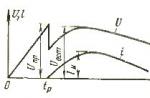
How the device works: The ATtiny13A microcontroller receives an interrupt at the moment the mains voltage passes through zero at the beginning of each half cycle. In the interrupt handling procedure, it reduces the pause time until the triac opens pulse is generated. Thus, with each interruption, the triac opens earlier, for an increasing time. At the end, a logical unit is applied to the triac control output and the microcontroller stops responding to interrupts. You can programmatically set any speed for turning on the lamp. In the basic version, this time is about two seconds.
The process of work is presented on a virtual oscillogram (all voltages are scaled for convenience). The red sine wave is the mains voltage. Yellow pulses - triggering of the zero crossing detector. Blue impulses - the opening of the triac.
The diagram of the incandescent lamp protection device is shown below. As already mentioned, it is a typical dimmer that software smoothly increases power from minimum to maximum.

The circuit introduced a circuit to protect the network from interference (a 100 Ohm resistor and a 10n capacitor parallel to the triac) that occur during pulse-phase regulation at the beginning of operation. The ATtiny13A microcontroller is powered by a transformerless source on a quenching capacitor.
The 100 Ohm noise suppression resistor must have a power of 0.5 W, quenching the resistor in front of the diode bridge of the zero detector by 82k - 1W. A 300 ohm current-limiting resistor in the microcontroller power circuit must have a power of 2W, a 470n quenching capacitor in the same circuit must be 630 volts.

The printed circuit board is drawn with a felt-tip pen, etched with blue vitriol, and contains only two shortcomings, eliminated with the help of wiring. Output signals for in-circuit programming. The small size allows you to place the protection device directly in the chandelier. The dimensions of the board can be further reduced if it is laid out more compactly.

Attention! The device is galvanically connected to the network, therefore, work in accordance with safety precautions, without touching the circuit with your hands.
Firmware (flash on Internal RC 9.6MHz):
UP 06/19/2014 The device was built into the chandelier on June 1, 2014. At this point, there were two working light bulbs in it. On June 19, one new light bulb was added. Let's try to collect some statistics on the life of the lamps.
UP 11/24/2014 Simplified circuit of the device: removed anti-jamming circuit and triac optocoupler.  In this regard, the dimensions of the printed circuit board are reduced.

Eagle file: soft_start_2.brd

After half an hour of work with firmware v2.0: R1 (SMD 2512), R2 (0.25W), D3 - warm, T1 - hot (without heat sink, load - 150 W). The power of the resistor R2 should be greater, as recommended in the first version of the circuit.
In this version, an annoying glitch was discovered: at the moment of switching on, the triac sometimes opens for a moment (in about 20% of cases). Sometimes this moment is enough to barely noticeably warm up the lamp filament. Not critical, but still, it's a glitch. The very first line of the program put a logical zero on the control electrode, but this does not help. The reason for this behavior is the controller or triac. An attempt at a solution is implemented in firmware version 2.1.
UP 01/15/2015 A simplified version of the device has been put into operation. We check.
UP 09/28/2015 The original (full) version broke today: in one of the bulbs, the filament still burned out, an arc formed, which led to a significant increase in the current consumption and failure of the triac. There are two options for improvement: installing a fuse or software current control. We are still thinking about the second one.
Source for Bascom:
$regfile = "attiny13a.dat" $crystal = 9600000 "triac control Config Portb.4 = Output "Portb.4 = 0" zero detector Config Int0 = Falling On Int0 Imp Config Timer0 = Timer , Prescale = 1024 "overflow in 0.032 sec On Timer0 Pulse Dim W As Byte Dim I As Byte Enable Interrupts Enable Timer 0 "Start Timer0 Enable Int0 W = 200" minimum glow at start I = 0 Do Loop End "zero detector interruption" the greater the value of W, the faster the timer will overflow Imp: Timer0 = W Start Timer0 Incr I If I = 5 Then Incr W I = 0 End If If W = 255 Then Stop Timer0 Disable Timer0 Disable Int0 Disable Interrupts Portb.4 = 1 "if you need to send the MC to sleep Powerdown End If Return "triac control Pulse: "timer overflow Stop Timer0 "stop the timer Portb.4 = 1 "triac turn on Waitus 100 Portb.4 = 0 "optotriac turn off Return
If there is interest in the device, the project will develop and improve. Please express your interest by liking the article on social networks (buttons at the end of the article).