On modern cars are used various systems fuel injection. The injection system (another name is the injection system, from injection - injection), as the name implies, provides fuel injection.
The injection system is used on both petrol and diesel engines. At the same time, the design and operation of injection systems for gasoline and diesel engines differ significantly.
In gasoline engines, injection forms a homogeneous fuel-air mixture, which is forced to ignite by a spark. In diesel engines, fuel is injected under high pressure, a portion of the fuel is mixed with compressed (hot) air and ignites almost instantly. The injection pressure determines the amount of injected fuel and, accordingly, the engine power. Therefore, the higher the pressure, the higher the engine power.
The fuel injection system is integral part vehicle fuel system. The main working body of any injection system is the nozzle ( injector).
Injection systems for gasoline engines
Depending on the method of formation of the fuel-air mixture, there are the following systems central injection, port injection and direct injection. Central and port injection systems are pilot injection systems, i.e. injection into them is carried out before reaching the combustion chamber - during intake manifold.
Diesel injection systems
Fuel injection in diesel engines can be done in two ways: into the pre-chamber or directly into the combustion chamber.
Pre-chamber injection engines feature low level noise and smooth operation. But at present, preference is given to direct injection systems. Despite elevated level noise, such systems have high fuel efficiency.
defining constructive element The injection system of a diesel engine is a high pressure fuel pump (high pressure fuel pump).
For cars with diesel engine various designs of injection systems are installed: with in-line injection pump, with distribution injection pump, pump nozzles, Common Rail. Progressive injection systems - pump nozzles and Common Rail system.
In the case of a fuel injection system, your engine is still sucking, but instead of relying solely on the amount of fuel being sucked in, the fuel injection system fires exactly the right amount of fuel into the combustion chamber. Fuel injection systems have already gone through several stages of evolution, electronics have been added to them - this was perhaps the biggest step in the development of this system. But the idea of such systems remains the same: an electrically activated valve (injector) sprays a measured amount of fuel into the engine. In fact, the main difference between a carburetor and an injector is precisely in electronic management ECU - exactly on-board computer delivers exactly the right amount of fuel to the combustion chamber of the engine.
Let's see how the fuel injection system and the injector in particular work.
What does the fuel injection system look like?
If the heart of a car is its engine, then its brain is the engine control unit (ECU). It optimizes the performance of the motor by using sensors to decide how to control some of the actuators in the motor. First of all, the computer is responsible for 4 main tasks:
- manages the fuel mixture,
- controls idle speed
- is responsible for the ignition timing,
- controls the valve timing.
Before we talk about how the ECU performs its tasks, let's talk about the most important thing - let's trace the path of gasoline from the gas tank to the engine - this is the work of the fuel injection system. Initially, after a drop of gasoline leaves the walls of the gas tank, it is sucked up by an electric fuel pump into the engine. Electric fuel pump, as a rule, consists of the pump itself, as well as a filter and a transmission device.
The fuel pressure regulator at the end of the vacuum-fed fuel rail ensures that the fuel pressure is constant with respect to the suction pressure. For a gasoline engine, fuel pressure is typically on the order of 2-3.5 atmospheres (200-350 kPa, 35-50 PSI (psi)). The fuel injectors are connected to the engine, but their valves remain closed until the ECU allows fuel to be sent to the cylinders.
But what happens when the engine needs fuel? This is where the injector comes into play. Usually injectors have two pins: one pin is connected to the battery through the ignition relay, and the other pin goes to the ECU. The ECU sends pulse signals to the injector. Due to the magnet, to which such pulsating signals are applied, the injector valve opens, and a certain amount of fuel is supplied to its nozzle. Since there is a very high pressure in the injector (the value is given above), the opened valve sends fuel at high speed to the nozzle of the injector nozzle. The duration with which the injector valve is open affects how much fuel is supplied to the cylinder, and this duration, respectively, depends on the pulse width (i.e., how long the ECU sends a signal to the injector).
When the valve opens, the fuel injector sends fuel through the spray tip, which atomizes the liquid fuel into mist, directly into the cylinder. Such a system is called system with direct injection . But the atomized fuel may not be supplied immediately to the cylinders, but first to the intake manifolds.

How the injector works
But how does the ECU determine how much this moment fuel to be supplied to the engine? When the driver presses the accelerator pedal, he actually opens throttle valve the amount of pedal pressure through which air is supplied to the engine. Thus, we can confidently call the gas pedal the "air regulator" to the engine. So, the car's computer is guided, among other things, by the throttle opening value, but is not limited to this indicator - it reads information from many sensors, and let's find out about them all!
Sensor mass flow air
First things first, the Mass Air Flow (MAF) sensor detects how much air is entering the throttle body and sends that information to the ECU. The ECU uses this information to decide how much fuel to inject into the cylinders to keep the mixture in ideal proportions.
Throttle position sensor
The computer constantly uses this sensor to check the throttle position and thus learn how much air is passing through the air intake in order to regulate the pulse sent to the injectors, ensuring that the correct amount of fuel enters the system.
Oxygen sensor
In addition, the ECU uses the O2 sensor to find out how much oxygen is in the car's exhaust. The oxygen content of the exhaust gases provides an indication of how well the fuel is burning. Using linked data from two sensors: oxygen and mass air flow, the ECU also monitors saturation fuel-air mixture supplied to the combustion chamber of the engine cylinders.
crankshaft position sensor
This is perhaps the main sensor of the fuel injection system - it is from him that the ECU learns about the number of engine revolutions at a given time and corrects the amount of fuel supplied depending on the number of revolutions and, of course, the position of the gas pedal.
These are the three main sensors that directly and dynamically affect the amount of fuel supplied to the injector and subsequently to the engine. But there are a number of other sensors:
- The voltage sensor in the electrical network of the car is needed so that the ECU understands how low the battery is and whether it is necessary to increase the speed in order to charge it.
- Coolant temperature sensor - ECU increases the number of revolutions if the engine is cold and vice versa if the engine is warm.
Engines with fuel injection systems, or injection engines, are almost forced out of the market carbureted engines. To date, there are several types of injection systems that differ in design and principle of operation. About how they are arranged and work Various types and types of fuel injection systems, read in this article.
Device, principle of operation and types of fuel injection systems
Today, most new passenger cars are equipped with fuel injection engines ( injection engines), which have better performance and are more reliable than traditional carbureted engines. We have already written about injection engines (article " Injection engine"), so here we will only consider the types and varieties of fuel injection systems.
There are two fundamental different types fuel injection systems:
Central injection (or single injection);
- Distributed injection (or multipoint injection).
These systems differ in the number of nozzles and their modes of operation, but their principle of operation is the same. In an injection engine, instead of a carburetor, one or more fuel injectors are installed, which spray gasoline into the intake manifold or directly into the cylinders (air is supplied to the manifold using a throttle assembly to form a fuel-air mixture). This solution makes it possible to achieve uniformity and High Quality combustible mixture, and most importantly - a simple setting of the engine operating mode depending on the load and other conditions.
The system is controlled by a special electronic unit (microcontroller), which collects information from several sensors and instantly changes the engine operating mode. In early systems, this function was performed mechanical devices However, today the engine is completely controlled by electronics.
Fuel injection systems differ in the number, installation location and mode of operation of the injectors.

1 - engine cylinders;
2 - inlet pipeline;
3 - throttle valve;
4 - fuel supply;
5 - electric wire, through which a control signal is supplied to the nozzle;
6 - air flow;
7 - electromagnetic nozzle;
8 - fuel torch;
9 - combustible mixture
This solution was historically the first and simplest, therefore, at one time it became quite widespread. In principle, the system is very simple: it uses one nozzle, which constantly sprays gasoline into one intake manifold for all cylinders. Air is also supplied to the manifold, so a fuel-air mixture is formed here, which enters the cylinders through the intake valves.
The advantages of single injection are obvious: this system is very simple, only one nozzle needs to be controlled to change the engine operating mode, and the engine itself undergoes minor changes, because the nozzle is put in place of the carburetor.
However, mono-injection also has disadvantages, first of all - this system cannot meet the ever-increasing requirements for environmental safety. In addition, the failure of one nozzle actually disables the engine. Therefore, today engines with central injection are practically not produced.
Distributed injection

1 - engine cylinders;
2 - fuel torch;
3 - electrical wire;
4 - fuel supply;
5 - inlet pipeline;
6 - throttle valve;
7 - air flow;
8 - fuel rail;
9 - electromagnetic nozzle
In systems with distributed injection, nozzles are used according to the number of cylinders, that is, each cylinder has its own nozzle located in the intake manifold. All nozzles combined fuel rail through which fuel is supplied.
There are several types of systems with distributed injection, which differ in the mode of operation of the nozzles:
Simultaneous injection;
- Pair-parallel injection;
- Phased spray.
Simultaneous injection. Everything is simple here - the nozzles, although they are located in the intake manifold of “their” cylinder, open at the same time. We can say that this is an improved version of mono-injection, since several nozzles work here, but the electronic unit controls them as one. Simultaneous injection, however, makes it possible to individually adjust the fuel injection for each cylinder. In general, systems with simultaneous injection are simple and reliable in operation, but they are inferior in performance to more modern systems.
Pair-parallel injection. This is an improved version of simultaneous injection, it differs in that the nozzles open in turn in pairs. Typically, the operation of the injectors is set in such a way that one of them opens before the intake stroke of its cylinder, and the second before the exhaust stroke. To date, this type of injection system is practically not used, however, modern engines provided emergency work engine in this mode. Typically, this solution is used when the phase sensors (camshaft position sensors) fail, in which phased injection is not possible.
phased injection. It is the most modern and providing best performance type of injection system. With phased injection, the number of nozzles is equal to the number of cylinders, and they all open and close depending on the stroke. Usually the nozzle opens just before the intake stroke - this is how best mode engine performance and economy.
Also to distributed injection include systems with direct injection, but the latter has cardinal design differences, so it can be separated into a separate type.

Direct injection systems are the most complex and expensive, but only they can provide best performance in terms of power and economy. Also, direct injection makes it possible to quickly change the engine operating mode, regulate the fuel supply to each cylinder as accurately as possible, etc.
In systems with direct fuel injection, the nozzles are installed directly in the head, spraying fuel directly into the cylinder, avoiding the "intermediaries" in the form of an intake manifold and an intake valve (or valves).
Such a solution is quite difficult in technical terms, since in the cylinder head, where the valves and the spark plug are already located, it is also necessary to place the nozzle. Therefore, direct injection can only be used in sufficiently powerful and therefore large engines. In addition, such a system cannot be installed on serial engine- it has to be modernized, which is associated with high costs. Therefore, direct injection is now used only on expensive cars.
Direct injection systems are demanding on fuel quality and require more frequent maintenance, however, they provide significant fuel savings and provide more reliable and high-quality engine operation. Now there is a tendency to reduce the price of cars with such engines, so in the future they can seriously push cars with injection engines of other systems.
D. Sosnin
We start publishing articles on modern fuel injection systems for gasoline engines internal combustion cars.
1. Preliminary remarks
Fuel supply of gasoline engines on modern cars implemented using injection systems. These systems, according to the principle of operation, are usually divided into five main groups (Fig. 1): K, Mono, L, M, D.

2. Advantages of injection systems
The air-fuel mixture (TV-mixture) is supplied from the carburetor to the cylinders of the internal combustion engine (ICE) through long intake manifold pipes. The length of these pipes to different engine cylinders is not the same, and in the collector itself there is an uneven heating of the walls, even on a fully warmed up engine (Fig. 2).

This leads to the fact that from a homogeneous TV mixture created in the carburetor, different cylinders Internal combustion engines produce unequal air-fuel charges. As a result, the engine does not deliver its design power, torque uniformity is lost, fuel consumption and the amount of harmful substances in the exhaust gases increase.
It is very difficult to deal with this phenomenon in carbureted engines. It should also be noted that a modern carburetor works on the principle of atomization, in which gasoline is atomized in a stream of air sucked into the cylinders. In this case, rather large drops of fuel are formed (Fig. 3, a),
That does not provide high-quality mixing of gasoline and air. Poor mixing and large droplets make it easier for gasoline to settle on the walls of the intake manifold and on the walls of the cylinders during the absorption of the TV mixture. But when gasoline is forced to be sprayed under pressure through a calibrated injector nozzle, fuel particles can be much smaller than when gasoline is sprayed during spraying (Fig. 3, b). Gasoline is sprayed especially effectively by a narrow beam under high pressure (Fig. 3, c).
It has been established that when gasoline is sprayed into particles with a diameter of less than 15–20 µm, its mixing with atmospheric oxygen occurs not as a particle weighing, but at the molecular level. This makes the TV mixture more resistant to temperature and pressure changes in the cylinder and long intake manifold pipes, which contributes to more complete combustion.
Thus, the idea was born to replace the spray jets of a mechanical inertial carburetor with a central inertial-free injection nozzle (CFI), which opens for a predetermined time according to an electric pulse control signal from the electronic automation unit. At the same time, in addition to high-quality atomization and efficient mixing of gasoline with air, it is easy to obtain a higher accuracy of their dosing in the TV mixture at all possible operating modes of the internal combustion engine.
Thus, due to the use of a fuel supply system with gasoline injection, the engines of modern passenger cars do not have the above disadvantages inherent in carbureted engines, i.e. they are more economical, have a higher specific power, maintain a constant torque over a wide range of speeds, and the emission of harmful substances into the atmosphere with exhaust gases is minimal.
3. Petrol injection system "Mono-Jetronic"
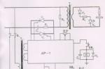
For the first time, the system of central single-point impulse fuel injection for gasoline engines of passenger cars was developed by BOSCH in 1975. This system was called "Mono-Jetronic" (Monojet - a single jet) and was installed on a Volkswagen car.On fig. 4 shows the central injection unit of the "Mono-Jetronic" system. It can be seen from the figure that central nozzle injection (CFV) is installed on a standard intake manifold instead of a conventional carburetor.

But unlike the carburetor, in which automatic mixture formation is implemented mechanical control, the mono injection system uses purely electronic control.
On fig. 5 shows a simplified functional diagram of the "Mono-Jetronic" system.

The electronic control unit (ECU) operates from input sensors 1-7, which record the current state and mode of operation of the engine. Based on the combination of signals from these sensors and using information from the three-dimensional injection characteristics, the ECU calculates the beginning and duration of the open state of the central injector 15.
On the basis of the calculated data in the ECU, an electrical impulse control signal S for the digital filter is generated. This signal acts on the winding 8 of the magnetic solenoid of the injector, the shut-off valve 11 of which opens, and through the spray nozzle 12, gasoline is forcibly sprayed at a pressure of 1.1 bar in the fuel supply line 19 into the intake manifold through the open throttle valve 14.
At given sizes of the throttle diaphragm and the calibrated section of the spray nozzle, the mass amount of air passed into the cylinders is determined by the degree of opening of the throttle valve, and the mass amount of gasoline injected into the air flow is determined by the duration of the open state of the nozzle and the boost (working) pressure in the fuel supply line 19.
In order for gasoline to burn completely and most efficiently, the masses of gasoline and air in the TV mixture must be in a strictly defined ratio, equal to 1/14.7 (for high-octane gasoline grades). This ratio is called stoichiometric, and it corresponds to the coefficient a of excess air equal to one. Coefficient a \u003d Md / M0, where M0 is the amount of air mass theoretically necessary for complete combustion given portion of gasoline, and Md is the mass of actually burnt air.
From this it is clear that in any fuel injection system there must be a meter for the mass of air admitted into the engine cylinders during suction.
In the "Mono-Jetronic" system, the air mass is calculated in the ECU according to the readings of two sensors (see Fig. 4): intake air temperature (AAT) and throttle position (TPP). The first one is located directly on the way air flow in the upper part of the central injection nozzle and is a miniature semiconductor thermistor, and the second is a resistive potentiometer, the engine of which is mounted on the rotary axis (PDA) of the throttle.
Since a specific angular position of the throttle valve corresponds to a strictly defined volumetric amount of air passed, the throttle potentiometer performs the function of an air flow meter. In the "Mono-Jetronic" system, it is also an engine load sensor.
But the mass of air taken in depends to a large extent on temperature. Cold air thicker and therefore heavier. As the temperature rises, the density of air and its mass decrease. The effect of temperature is taken into account by the DTV sensor.
The DTV intake air temperature sensor, as a semiconductor thermistor with a negative temperature coefficient of resistance, changes the resistance value from 10 to 2.5 kOhm when the temperature changes from -30 to +20°C. The DTV sensor signal is used only in such temperature range. In this case, the basic duration of petrol injection is corrected by the ECU in the range of 20...0%. If the intake air temperature is above + 20 ° C, then the DTV sensor signal is blocked in the ECU and the sensor is not used.
The signals from the throttle position sensors (DPD) and intake air temperature (DTV) in cases of their failures are duplicated in the ECU by the signals of the speed sensors (DOD) and the engine coolant temperature (DTD).
The air volume calculated in the ECU and the engine speed signal from the ignition speed sensor determine the required (basic) duration for the central injection nozzle to be open.
Since the boost pressure Pt in the fuel supply line (PBM) is constant (for "Mono-Jetronic" Pt = 1 ... 1.1 bar), and throughput nozzle is given by the total cross section of the spray nozzle openings, then the time of the open state of the nozzle uniquely determines the amount of injected gasoline. The moment of injection (in Fig. 5, the signal from the DMV sensor) is usually set simultaneously with the signal to ignite the TV mixture from the ignition system (through 180° of rotation of the engine crankshaft).
Thus, with electronic control of the mixture formation process, ensuring a high accuracy of dosing of injected gasoline into a measured amount of air mass is an easily solved problem, and, ultimately, the dosing accuracy is determined not by electronic automation, but by the manufacturing accuracy and functional reliability of the input sensors and the injection nozzle.
On fig. 6 shows the main part of the "Mono-Jetronic" system - the central injection nozzle (CFI).

The central injection nozzle is a petrol valve, which is opened by an electrical impulse coming from electronic block management. To do this, the nozzle has an electromagnetic solenoid 8 with a movable magnetic core 14. The main problem in creating valves for pulsed injection is the need to ensure high speed operation of the shut-off device 9 of the valve both for opening and closing. The solution to the problem is achieved by lightening the magnetic core of the solenoid, increasing the current in the pulse control signal, selecting the elasticity of the return spring 13, and also the shape of the ground surfaces for the spray nozzle 10.
The nozzle nozzle (Fig. 6, a) is made in the form of a socket of capillary tubules, the number of which is usually at least six. The angle at the top of the socket is set by the opening of the injection jet, which has the shape of a funnel. With this form, the jet of gasoline does not hit the throttle even with its small opening, but flies into two thin crescents of the opened slot.
The central nozzle of the "Mono-Jetronic" system reliably ensures the minimum duration of the open state of the spray nozzle 11 within 1 ± 0.1 ms. During such a time and at an operating pressure of 1 bar, about one milligram of gasoline is injected through a spray nozzle with an area of \u200b\u200b0.08 mm2. This corresponds to a fuel consumption of 4 l/h at minimum idling(600 rpm) warm engine. When starting and warming up a cold engine, the injector opens for a longer time (up to 5...7 ms). But on the other hand, the maximum duration of injection on a warm engine (time of the open state of the injector) is limited by the maximum speed of the engine crankshaft (6500 ... 7000 min-1) in full throttle mode and cannot be more than 4 ms. In this case, the clock frequency of operation of the locking device of the injector at idle is not less than 20 Hz, and at full load - not more than 200...230 Hz.
With special care, the DPD throttle position sensor (throttle potentiometer), shown in fig. 7. Its sensitivity to the rotation of the engine must meet the requirement of ±0.5 angular degrees of rotation of the axis 13 of the throttle. According to the strict angular position of the throttle axis, the beginnings of two engine operation modes are determined: idle mode (3 ± 0.5 °) and full load mode (72.5 ± 0.5 °).
To ensure high accuracy and reliability, the resistive tracks of the potentiometer, of which there are four, are connected according to the circuit shown in fig. 7, b, and the axis of the potentiometer slider (two-pin slider) is seated in a backlash-free Teflon plain bearing.
The potentiometer and the ECU are connected to each other by a four-wire cable through a connector. To increase the reliability of the connections, the contacts in the connector and in the potentiometer chip are gold-plated. Pins 1 and 5 are for supplying reference voltage 5 ± 0.01 V. Contacts 1 and 2 - to remove the signal voltage when the throttle valve is turned at an angle from 0 to 24 ° (0 ... 30 - idle mode; 3 ... 24 ° - low engine load mode) . Contacts 1 and 4 - to remove the signal voltage when the throttle valve is turned at an angle of 18 to 90 ° (18 ... 72.5 ° - medium load mode, 72.5 ... 90 ° - engine full load mode).
The signal voltage from the throttle potentiometer is additionally used:
to enrich the TV mixture during acceleration of the car (the rate of change of the signal from the potentiometer is recorded);
to enrich the TV mixture in full load mode (the value of the signal from the potentiometer is recorded after 72.5 ° turning the throttle upwards);
to stop fuel injection in the forced idle mode (a potentiometer signal is recorded if the throttle valve opening angle is less than 3 °. At the same time, the engine speed W is monitored: if W> 2100 min-1, then the fuel supply is stopped and restored again at W
An interesting feature injection system "Mono-Jetronic" is the presence in its composition of a subsystem for stabilizing idle speed using an electric servo drive that acts on the throttle axis (Fig. 8). The electric servomotor is equipped with a reverse electric motor 11 DC.

The servo drive is activated in idle mode and, together with the circuit for turning off the vacuum ignition timing regulator (idling stabilization - Fig. 2), ensures stabilization of the engine speed in this mode.
Such an idle stabilization subsystem works as follows.
When the throttle open angle is less than 3°, signal K (see Fig. 9)

It is an idle mode signal for the ECU (the limit switch VK is closed by the servo rod). On this signal, the shut-off pneumatic valve of the ZPK is activated and the vacuum channel from the throttle zone of the intake manifold to the BP vacuum regulator is blocked. Vacuum regulator from that moment on, it does not work and the ignition timing becomes equal to the value of the setting angle (6 ° to TDC). At the same time, the engine runs stably at idle. If at this time the air conditioner or other powerful consumer of engine energy (for example, headlights high beam indirectly through the generator), then its speed begins to fall. The engine may stall. To prevent this from happening, at the command of electronic circuit idle control (ESHH) in the controller, the electric servo is turned on, which slightly opens the throttle valve. RPM is increased to the nominal value for a given engine temperature. It is clear that when the load is removed from the engine, its speed is reduced to the norm by the same electric servo drive.
The ECU of the "Mono-Jetronic" system has a MCP microprocessor (see Fig. 5) with permanent and random-access memory (memory unit). The reference three-dimensional injection characteristic (THV) is "hardwired" into the permanent memory. This characteristic is somewhat similar to the three-dimensional ignition characteristic, but differs in that its output parameter is not the ignition timing, but the time (duration) of the open state of the central injection nozzle. The input coordinates of the TXV characteristic are the engine speed (the signal comes from the ignition system controller) and the intake air volume (calculated by the microprocessor in the injection computer). Reference characteristic TXV carries reference (basic) information about the stoichiometric ratio of gasoline and air in the TV mixture under all possible modes and conditions of engine operation. This information is selected from the memory memory into the microprocessor of the computer according to the input coordinates of the characteristics of the TXV (according to the signals of the DOD, DPD, DTV sensors) and is corrected according to the signals from the coolant temperature sensor (CTD) and oxygen sensor(KD).
About the oxygen sensor must be said separately. Its presence in the injection system allows you to keep the composition of the TV-mixture constantly in the stoichiometric ratio (a=1). This is achieved by the fact that the CD sensor operates in a deep adaptive circuit. feedback from the exhaust system to the fuel supply system (to the injection system).
It reacts to the difference in the concentration of oxygen in the atmosphere and in the exhaust gases. Essentially, the KD sensor is chemical source current of the first kind (galvanic cell) with a solid electrolyte (special honeycomb cermet) and high (not lower than 300°C) operating temperature. The EMF of such a sensor almost according to a stepwise law depends on the difference in the oxygen concentration on its electrodes (platinum-radium film coating with different parties porous ceramics). The greatest steepness (difference) of the EMF step falls on the value a=1.
The KD sensor is screwed into the pipe of the exhaust channel (for example, into exhaust manifold) and its sensitive surface (positive electrode) is in the flow exhaust gases. Above the mounting thread of the sensor there are slots through which the outer negative electrode communicated with atmospheric air. On vehicles with a catalytic gas converter, the oxygen sensor is installed in front of the converter and has an electric heating coil, since the temperature of the exhaust gases in front of the converter can be below 300 ° C. In addition, the electrical heating of the oxygen sensor speeds up its preparation for operation.
The sensor is connected by signal wires to the injection computer. When the cylinders enter lean mixture(a>1), then the oxygen concentration in the exhaust gases is slightly higher than the standard one (at a=1). The CD sensor produces low voltage(about 0.1 V) and the ECU, using this signal, corrects the petrol injection duration time in the direction of its increase. The coefficient a again approaches unity. When the engine is running on rich mixture the oxygen sensor outputs a voltage of about 0.9 V and works in reverse.
It is interesting to note that the oxygen sensor is involved in the process of mixture formation only in engine operating modes, in which the enrichment of the TV mixture is limited by the value a > 0.9. These are modes such as load at low and medium speeds and idling on a warm engine. Otherwise, the KD sensor is disabled (blocked) in the ECU and the composition of the TV mixture is not corrected for the oxygen concentration in the exhaust gases. This takes place, for example, in the modes of starting and warming up a cold engine and in its forced modes (acceleration and full load). In these modes, a significant enrichment of the TV mixture is required and, therefore, the operation of the oxygen sensor ("pressing" the coefficient a to unity) is unacceptable here.
On fig. 10 shows a functional diagram of the "Mono-Jetronic" injection system with all its components.
Any injection system in its fuel supply subsystem necessarily contains a closed fuel ring, which starts from the gas tank and ends there. This includes: BB gas tank, EBN electric fuel pump, filter fine cleaning FTOT fuel, RT fuel distributor (in the "Mono-Jetronic" system - this is the central injection nozzle) and the pressure regulator RD, operating on the principle of a bleed valve when the specified operating pressure in the closed ring is exceeded (for the "Mono-Jetronic" system 1 ... 1.1 bar).
Closed fuel ring performs three functions:
By means of a pressure regulator maintains the required constant operating pressure for fuel distributor;
By means of a spring-loaded diaphragm in the pressure regulator, it maintains a certain residual pressure (0.5 bar) after the engine is switched off, which prevents the formation of steam and air locks V fuel lines when the engine cools down;
Provides cooling of the injection system due to the constant circulation of gasoline in a closed circuit. In conclusion, it should be noted that the "Mono-Jetronic" system is used only on passenger cars of the middle consumer class, such as West German cars: "Volkswagen-Passat", "Volkswagen-Polo", "Audi-80".
REPAIR&SERVICE-2"2000
Dear readers and subscribers, it's nice that you continue to study the structure of cars! And now for your attention electronic system fuel injection, the principle of which I will try to tell in this article.
Yes, it is about those devices that have replaced the time-tested power supplies from under the hoods of cars, and we will also find out if modern gasoline and diesel engines have much in common.
Perhaps we would not have discussed this technology with you if a couple of decades ago humanity had not seriously taken care of the environment, and one of the most serious problems turned out to be toxic traffic fumes cars.
The main drawback of cars with engines equipped with carburetors was incomplete combustion of fuel, and in order to solve this problem, systems were needed that could regulate the amount of fuel supplied to the cylinders depending on the operating mode of the engine.
Thus, injection systems or, as they are also called, injection systems, appeared on the automotive arena. In addition to improving environmental friendliness, these technologies have improved the efficiency of engines and their power characteristics, becoming a real boon for engineers.
Today, fuel injection (injection) is used not only on diesel engines, but also on petrol units which undoubtedly unites them.
They are also united by the fact that the main working element of these systems, whatever type they are, is the nozzle. But due to differences in the method of burning fuel, the designs of the injection units for these two types of engines, of course, differ. Therefore, we will consider them in turn.
Injection systems and gasoline
Electronic fuel injection system. Let's start with gasoline engines. In their case, injection solves the problem of creating air-fuel mixture, which is then ignited in the cylinder by a spark from a spark plug.
Depending on how this mixture and fuel is supplied to the cylinders, injection systems can have several varieties. The injection happens:
central injection
The main feature of the technology located first in the list is one single nozzle for the entire engine, which is located in the intake manifold. It should be noted that this type injection system in terms of its characteristics, it does not differ much from the carburetor, therefore, today it is considered obsolete.

Distributed injection
More progressive is distributed injection. In this system fuel mixture it is also formed in the intake manifold, but, unlike the previous one, each cylinder here boasts its own nozzle.
This variety allows you to experience all the advantages of injection technology, therefore it is most loved by automakers, and is actively used in modern engines.

But, as we know, there are no limits to perfection, and in pursuit of even more high efficiency, engineers developed an electronic fuel injection system, namely a direct injection system.
Her main feature is the location of the nozzles, which, in this case, with their nozzles go into the combustion chambers of the cylinders.

The formation of the air-fuel mixture, as you might guess, occurs directly in the cylinders, which has a beneficial effect on operating parameters engines, although this option is not as high as that of distributed injection, environmental friendliness. Another tangible drawback of this technology is the high requirements for the quality of gasoline.
Combined injection
The most advanced in terms of emissions of harmful substances is combined system. This is, in fact, a symbiosis of direct and distributed fuel injection.

How about diesels?
Let's move on to diesel units. Before them fuel system the task is to supply fuel under very high pressure, which, mixing in the cylinder with compressed air, ignites on its own.
A lot of options for solving this problem have been created - both direct injection into cylinders and with an intermediate link in the form of a preliminary chamber are used, in addition, there are various pump arrangements high pressure(TNVD), which also adds variety.
However, modern motorists prefer two types of systems that supply diesel fuel directly to the cylinders:
- with pump nozzles;
- common rail injection.
Pump nozzle
The pump-injector speaks for itself - in it the nozzle that injects fuel into the cylinder, and the high-pressure fuel pump are structurally combined into one unit. the main problem such devices is increased wear, since the unit injectors are connected permanent drive with a camshaft and never disconnect from it.