Owners of carbureted cars are familiar with the difficulties of the ignition adjustment process. Usually this is done by ear, which is not very convenient. Using a stroboscope, this process can be facilitated. However, industrial devices are quite expensive, so many make a strobe for ignition with their own hands.
Disadvantages of industrial models
Industrial devices often have certain disadvantages, due to which the usefulness of the device is very doubtful.
For starters, they are quite pricey. For example, modern digital models will cost a motorist 1000 rubles. More functional models already cost from 1700. Advanced stroboscopes cost about 5500 rubles. Needless to say, a car stroboscope (made with your own hands) will cost a motorist 100-200 rubles.
Often in factory devices, the manufacturer uses a particularly expensive discharge lamp. The lamp has a certain resource, and after a while it will have to be replaced. And this in itself is tantamount to acquiring a new factory device.
Why is it worth making a stroboscope with your own hands?
The disadvantages of factory and technological devices are pushing the motorist to independently manufacture this device. In addition, it is much cheaper to equip this equipment with LEDs instead of an expensive lamp. An ordinary laser pointer or flashlight is suitable as a source of diodes or a donor.
The rest of the details will also cost a penny. It does not require any special tools. The budget for the manufacturing process of a stroboscope will be no more than 100 rubles.
How to make a stroboscope with your own hands?
There are a huge number of schemes and options for manufacturing. However, for the most part, all projects to create this gadget are similar. Let's see what is needed for assembly.

We need a simple transistor KT315. It can be easily found in an old Soviet receiver. The designation may be slightly different, but it does not matter. The thyristor KU112A can be easily obtained from the power supply of an old TV. You can also find small resistors there. Since we make an LED strobe with our own hands, then, of course, we need an LED flashlight. To do this, it is better to purchase the cheapest one from China. In addition, you need to stock up on a capacitor up to 16 V with any low-frequency diode, a small 12 A relay, wires, crocodiles, a shielded wire 0.5 m long, and a small piece of copper wire.
We assemble the device
The scheme is small, and you can place it right in the same Chinese lantern. So, through the hole in the flashlight at the back, it is desirable to pass the wires to power the device. At the ends of the wires, it is better to solder crocodiles. A hole needs to be made in the side wall, if the Chinese have not already made it. A shielded wire will be routed through this hole. At the opposite end, it is necessary to insulate the braid and solder the same piece of copper wire to the main core of the wire. This will be the sensor.
Device diagram and principle of operation
After applying current through the power wires, the capacitor will charge very quickly through the resistor. When a certain charge threshold is reached, the voltage will flow through the resistor to the opening contact of the transistor. This is where the relay comes in. When the relay closes, it will create a circuit of thyristor, LED and capacitor. Then, through the divider, the pulse will go to the control output of the thyristor. Next, the thyristor will open, and the capacitor will be discharged to the LEDs. As a result, a do-it-yourself stroboscope will flash brightly.

Through a resistor and a thyristor, the base output of the transistor is connected to a common wire. Because of this, the transistor will close, and the relay will turn off. The time of the glow of the LEDs increases, since the contact is not broken immediately. But the contact will break, and the thyristor will be de-energized. The circuit will return to its base position until a new pulse arrives.
By changing the capacitance of the capacitor, you can change the glow time. If you choose a capacitor with a larger capacity, then the LED stroboscope, made by yourself, will glow brighter and last longer.
device on a microcircuit
The main part of this simple circuit is a DD1 chip. This is the so-called single vibrator 155AG1. In this circuit, it starts only from negative pulses. The control signal will go to the KT315 transistor, and it will generate these negative pulses. Resistors 150 K ohm, 1 k ohm, 10 k ohm, as well as the KS139 zener diode work as limiters for the amplitude of the incoming signal from the ignition of the car.
A 0.1 mF capacitor, together with a 20 kΩ resistance, will set the desired duration of the pulses that will be generated by the microcircuit. With such a capacitance of the capacitor, the duration of the pulses will be up to about 2 ms.
Then, from the 6th leg of the microcircuit, the pulses, which by this moment will be synchronized with the ignition of the car, will go to the base output of the KT 829 transistor. It is here as a key. The result is a pulsed current through the LEDs.

How is this auto strobe powered? With our own hands, we need to run a couple of wires to the terminals of the car battery. It is necessary to monitor the level of battery charge.
If you correctly assemble this simple circuit, you will immediately be able to see how the device works. If suddenly the brightness is not enough, then this is regulated by the selection of the appropriate resistance.
As a housing for the device, you can use an old or Chinese flashlight.
Another stroboscope circuit
This do-it-yourself LED stroboscope, made according to this principle, can also be powered from a car battery. Diodes will provide protection against reverse polarity. As a fastener, an ordinary crocodile is used here. It must be attached to the high voltage contact of the first spark plug on the motor. Next, the pulse will pass through the resistors and the capacitor and come to the input of the trigger. By that time, this input will already be turned on by the one-shot.
Before the pulse, the one-shot is in normal mode. The direct trigger output is low. Inverted input, respectively - high. A capacitor connected with a plus to the inverted output will be charged through a resistor.
A high-level pulse fires a one-shot, which switches the flip-flop and serves to charge the capacitor through the resistor. After 15 ms, the capacitor will be fully charged and the trigger will switch to normal mode.
As a result, the one-shot will respond to this with a synchronous sequence of rectangular pulses with a duration of approximately 15 ms. The duration can be adjusted by changing the resistor and capacitor.

The pulses of the second microcircuit are up to 1.5 ms. For this period, transistors open, which are an electronic switch. Then current flows through the LEDs. According to this principle, a strobe for a car works (it was made by hand or not, it does not matter - both devices shine the same way).
The current passing through the LEDs is much greater than the passport one. But, since the flashes are short, the LEDs will not fail. The brightness will be enough to use this useful device even in the daytime.

This do-it-yourself stroboscope can be assembled in a case from the same long-suffering pocket flashlight.
How to work with the device?
Having assembled the device according to one of the above schemes, you can simply and easily, and most importantly, accurately adjust the ignition on carburetor engines, check the correct operation of candles and coils, and control the operation of the advance angle regulators.
In order to set the ignition as correctly as possible, it is usually assumed that the mixture ignites a couple of degrees before the piston reaches its highest point. This angle is called the "advance angle". As the crankshaft rpm increases, the angle should also increase. So, this angle is set at idle, and then it is necessary to check the correctness of the settings in all operating modes of the unit.
We set the ignition
We start and warm up the engine. Now we power our LED stroboscope and connect the sensor. Now you need to point the device at the mark on the timing case and find the mark on the flywheel. If the moment is violated, then the marks will be far enough apart. By rotating the timing case, match the marks. When you have found this position, fix the distributor.

Then it's time to pick up the pace. The labels will diverge, but this is a completely normal situation. This is how the ignition is adjusted using a stroboscope.
So, we found out how a do-it-yourself LED stroboscope is made.
Surely many of us would like to have a stroboscope at home to decorate a small party and give it a little drive. As a rule, they are made on flash lamps, but unfortunately they are quite expensive and have a small resource.
I decided to replace the lamps with LEDs, and I can say with confidence that even a beginner radio amateur can make such a stroboscope with his own hands for a disco.
The stroboscope itself is assembled on 2 printed circuit boards, one of them has LEDs, and the second one has a control unit. The main part in the control unit is the LM555 timer chip.
It is she who generates pulses, the frequency of which determines how quickly the strobe will flicker, and is regulated by a variable resistor. I used 60 LEDs, but you can use any multiple of 3 (3, 6, 9...).
As a power supply, any source from 6 to 12 volts is suitable. It works for me from one Krona battery, but if you wish, you can connect it to a 12-volt power supply (an additional connector is provided for this). In this case, the strobe shines much brighter.
Here is a list of radio components that will be needed in the manufacture of a stroboscope:
- Super-bright LEDs (white, 5 mm) - 60 pcs;
- Chip-timer 555;
- Polevik IRFZ44N;
- Variable resistor 1 mΩ;
- Resistor 5.6 ohm (2 W);
- Resistor 56 Ohm;
- Resistor 10 kΩ;
- Resistor 100 kΩ;
- Capacitor 1uF x 50V;
- Capacitor 1000uF x 16V;
- Diode 1N4148;
Body parts and other small things:
- Plastic case 90×60×25 mm;
- Plexiglas 90×60 mm;
- Textolite;
- Racks M4 × 22 mm (mother-mother) - 4 pcs;
- Racks M4 × 10 mm (mother-father) - 4 pcs;
- Screws for racks М3×8 mm;
- Battery "Krona" + reciprocal connector for it;
- Power connector (male);
- Sliding switch (2 positions);
The schematic and PCB were drawn in the program Eagle. The control board turned out to be small, if desired, it can be made even smaller using smd Components. The dimensions of the board with LEDs are 87 by 57 mm.
(PDF, 62 Kb);
(PDF, 13 Kb);
(PDF, 48 Kb);
(PDF, 10 Kb);
(PDF, 47 Kb).


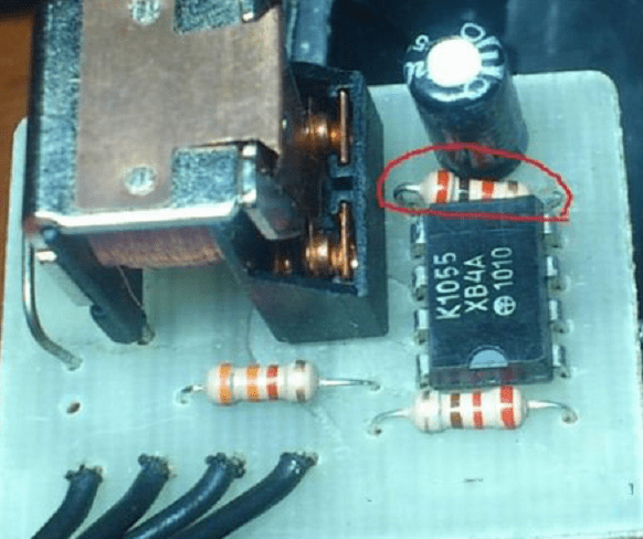
Unfortunately, I did not take photos during the soldering process, but I hope that this will not be a hindrance to you. Here are some photos showing already soldered circuit boards for the stroboscope.


After manufacturing printed circuit boards and soldering radioelements on them, you can proceed to packaging.


Inside the case, I had to cut off several plastic racks that interfered.

To protect the LEDs, I used plexiglass, installing it on stands (between plexiglass and the strobe body - 10 mm).


Now it remains only to insert all the connectors, tighten the bolts and do-it-yourself stroboscope for the disco is ready!


Here is a video of the strobe in action:
Note: If you want to make a colored strobe, you can use RGB LEDs (which is quite expensive), or cut out various filters from colored plexiglass.
The interest of the modern motorist is not limited to attention to the car as a means of transportation. In many respects, the effect and impression that can be made on all participants in the movement is important. After a widespread ban on imitators of flashing lights of law enforcement officers and official cars, somehow unexpectedly, the fashion for a stroboscope on the grill and a double signal began to gain momentum.
Most of the above schemes are not designed to completely imitate the signals of official cars, it is rather a purely sporting interest. And to whom and for what to pay fines, everyone decides for himself, based on his capabilities.
There are several simple ways to organize a stroboscope on a car, it all depends on the amount of effort and money that can be spent to build a car stroboscope. Most often, they try to get the most realistic flickering of strobe lamps.
Several simple schemes of LED strobe lights for cars have been tested in practice:
- according to the simplest scheme using two relays 494.3787;
- based on the 555 timer and the k561ie8 circuit;
- on the PIC12F675 microcontroller;
- on the element base transistors 315 series.
For your information! The safest and most popular way is to use a flashing effect by installing LEDs in your car headlights. It's beautiful and stylish.
We assemble a car stroboscope with our own hands
The easiest way to build a reliable circuit on a car is to use a couple of relays from the gazelle turn signal system, a starter relay and a couple of trimming resistors. It is easy to assemble such a stroboscope circuit with your own hands, and even special knowledge or skills are not required.
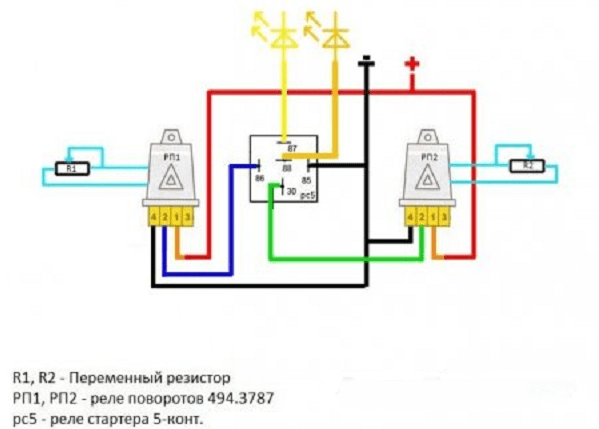
The specified scheme provides for the connection to the daytime running lights of the car. If desired, you can switch the connected daytime running lights or strobe flashers. The advantage of this approach is the absence of overload-sensitive electronic components in the circuit. The relays, even in the event of an overload of the electrical circuit, in most cases will remain intact, although they can lead to blown fuses.
To build a strobe circuit, the following is required.
- First, we disassemble the case of the turn relay and carefully remove the white constant resistor with numerous transverse colored stripes.
- In a variable resistance of 20-25 kOhm, we solder the middle electrode to one of the side ones.
- We solder the variable resistance instead of the removed element in such a way that, after reassembly, the rotary stem of the variable resistor could be freely rotated.
- We assemble the circuit, we carry out a similar procedure with the second relay.
- We assemble the circuit shown in the figure, and after applying the supply voltage by turning the control rods, we select and synchronize the flashing frequency of the strobe lights on the car.
If you use a variable resistance of 450 kOhm, the blinking frequency will be much less, but for a more accurate selection of the blinking frequency, you can select several different resistances and achieve the required frequency.

Building a circuit based on a microprocessor
The most “advanced” motorists in the basics of microelectronics believe that the controller-based stroboscope circuit will be the most effective. On the PIC12F675 microcontroller, the circuit will be able to provide current pulses up to one ampere with adjustable duration.
The stroboscope circuit for a car is easy to assemble with your own hands. As a load, a package of light elements is most often used, with the ability to change the flicker frequency of the stroboscope on LEDs. The processor itself controls two powerful KT817 transistors and can produce seven different combinations of signals. The system itself is quite common in industrial circuits for service flashers, especially for simple strobe systems on a car radiator grille.
The most unpleasant thing in connecting such circuits is the high sensitivity of any microprocessors to overvoltage or the occurrence of a short circuit mode. Therefore, when assembling and soldering, it is imperative to use a good ground. In addition, the use of a stabilized power supply is mandatory; usually, a circuit on a paired low-voltage zener diode is used for these purposes.
When connecting the stroboscope circuit to the car's electrical wiring circuit, you must first completely disconnect the power from the battery, it is strictly forbidden to start and test the circuit in the absence of load.
Do-it-yourself police stroboscope on a logic counter
To obtain an effect similar to the flickering of LEDs in a strobe on law enforcement service motors, you can use an interesting option on the 561 series logic counter and 555 timer. The circuit turns out to be somewhat more complicated than previous developments, but if you have a couple of hours of free time and the ability to solder, you can assemble a small homemade product on a printed circuit board.
As a load, packages of LEDs with a total current consumption of not more than 3A are used; if desired, they can be replaced with low-power halogen lamps with a total power consumption of up to 30 W.
The specificity of constructing such a stroboscope circuit on LEDs is an interesting feature of the formation of a control signal. The microcircuit on the 555 assembly acts as a source of a control signal input to the counter. Without going into the specifics of the operation of the stroboscope, we can only note that the ignition and extinguishing circuit of the LEDs was copied from the stroboscope of a police car.
Rectangular pulses are fed to the counter and summed up. After a certain programmable time, the potential on the control contact changes from high to low.
The stroboscope works like this: each of the LED packages flashes, gives a certain programmed number of flashes and goes out, then the signal is transmitted to the next LED package and so on in a cyclic mode.
Important! Powerful KT819 or bipolar KT818 are used as control keys in the stroboscope circuit, which allows you to control high currents in the load.
To power the 555 microcircuit, the maximum supply voltage cannot be increased more than 18 volts, the stabilizer is not designed for a larger operating range, and the circuit remains operational even when the voltage drops to 5 V.

How to make a stroboscope with your own hands on simple spare parts
The most budgetary way to build a do-it-yourself LED stroboscope is not to buy a bunch of spare parts on the radio market for a couple of thousand, but to try to use old Soviet or Chinese spare parts.
We use mikruha 155 series as a signal source, AG1 can be used. After power is applied, the microcircuit sets a positive potential at the control pin, and as the capacitor charges, the potential drops and opens the control signal to the KT315. The capacitance of the capacitor determines the length of the flash, at 0.1 uF it will be approximately 0.01 sec, which is quite enough to obtain the desired optical effect.
On the 6th leg 155 of the microassembly, a series of pulses will be generated, coupled with the pulses of the ignition system. They fall on the control electrodes of two KT 829 transistors. Then the transistor opens, and a significant current will flow through the load from the LEDs.
If the stroboscope circuit consumes more than 60 watts, use standard aluminum radiators to cool the transistors.
The result, or the design of strobe LEDs for cars
For most fans of homemade strobe lights, it is sometimes more important to hide the fact of owning homemade light illumination similar to a police one. Therefore, often the package of light bulbs or LEDs is made removable so that it can be easily installed on the hood or roof of a car. Sometimes, for greater disguise, an easily removable plastic cover is put on top of such a block, in appearance it strongly resembles a taxi lantern.
The advantage of this design solution is that the stroboscope fixture is easy to remove and even throw away. A stroboscope with a plastic case on top will resemble a taxi driver's lantern and will not attract the attention of the police in the parking lot or when the car accidentally stops on the road.

The second installation option is to install a package of strobe LEDs in the area of \u200b\u200bthe radiator grille of a car or in the cavity of a headlight lamp. This is a more expensive and effective way, as it will require some alteration of the car's optics, and in the event of a conflict with law enforcement officers, it can become the basis for placing the car in a car impound.
Why does a motorist need a stroboscope? A real amateur is always looking for a way to get the most frisky and accurate ignition from the engine of his swallow. In classic distributor ignition systems, the strobe for setting the ignition is, in fact, the only possible accurate way to see the ignition timing with your own eyes. You can, of course, ignore the overheating engine and "get" for a major overhaul.
You can do it a little differently:
- to beg an electronic device from a neighbor and pay its cost in case of a product breakdown;
- buy a stroboscope for installing an ignition with a bunch of additional ridiculous functions on the market or in a store, and at the same time throw out completely unnecessary 2-3 thousand rubles;
- make a stroboscope for installing the ignition with your own hands “on the knee”. Be able to use it yourself and rent out the device for adjusting the ignition timing.
The principle of operation of the stroboscope for setting the ignition
In general, the thing is extremely useful, and among amateurs it is in demand and authority. The principle of operation of a stroboscope for ignition is based on the specific property of human vision to summarize a series of instant pictures into one picture. At the heart of any such device is a pulsed low-inertia lamp.
At the command of a small control circuit, the lamp flashes at a certain, but very precise frequency. If in the dark we illuminate, for example, a rotating disk with a white risk, then due to the above effect we will see a frozen disk with a fixed risk. If the disk rotates unevenly, then in our eyes the risk will shift.
How to use a strobe light to set the ignition
When setting the OZ angle, the device sends flashes of a lamp or LED to the crankshaft pulley with a TDC risk and notes its displacement relative to the marks on the tide next to the pulley. As a signal indicator for lamp ignition, a capacitive sensor is used on the armored wire of the first candle.
Seeing the actual position of the mark on the pulley relative to the reference point, using a stroboscope, the ignition timing is set. On a running engine, they simply turn the distributor left and right with their own hands until they see the alignment of the mark on the pulley with the point of setting the required angle.

Homemade stroboscope designs for ignition installation
Now on the market you can buy a lot of useful things for setting up and adjusting the motor, but beautiful “toys” have no fundamental advantages over homemade products, they cost more and break more often. It is much easier and cheaper to make a stroboscope circuit for installing the ignition with your own hands. It takes quite a bit of patience, a soldering iron and a dozen parts.
Stroboscope for setting the ignition of two transistors
The cost of such a model of a stroboscope will cost you five hundred rubles, and the element base used consists of:
- pairs of KT315 - the most common Soviet transistors that are easy to find in any electronic toy;
- a dozen low-power resistors of various denominations, KU112A;
- a pair of capacitors, one electrolyte at 47 microfarads, the second is ordinary, for 47 picks;
- KD series diode
- with a dozen LEDs, better than lanterns.
Also, to connect a stroboscope for ignition with your own hands, you will need a copper wire, a couple of meters of two-wire with clamps.

We assemble the design of the stroboscope with our own hands according to the layout of the circuit, you can even mount it by hanging, but it is better on a prepared board. There are no special tricks in installation and connection when establishing a UOZ, therefore, with careful soldering, everything should work from the first push.
You can check the schema. After applying voltage from the battery, we close the output with a copper contact for the “armor” with a positive terminal. If the relay buzzes, the circuit is in order.
By selecting the electrolyte capacity, you can set the duration of the LED burning, but it is better to use the recommended ratings. When the flash is too large and bright, it is not always convenient to set the correct angle, because the image of the marks is slightly blurred. Therefore, the optimal capacity will be slightly less than the recommended 47 microfarads.
Important! If you have experience with a stroboscope for setting the ignition, the circuit can be soldered right on the car with a flashlight output and a switch in a convenient place, otherwise, don't risk it.
Connecting and installing a do-it-yourself stroboscope comes down to supplying power from the battery to the board contacts and fixing the copper core on top of the high-voltage "armored car" of the first candle. Be sure to check the power polarity before turning on the strobe.
The circuit is simple and reliable, but how accurate the flashes emitted by the strobe have temporal characteristics depends on many factors, including the quality of the assembly and the correct installation of the circuit.
Enhanced strobe variant
If working with radio components does not annoy you and you have the skill, you can try to make and install a more complex version of the stroboscope. The circuit uses the NE555 assembly, so the duty cycle is much better. Most similar designs and schemes use KR1006VI1 with a bunch of additional attachments. As a result, installing a stroboscope for ignition is more expensive, although it can potentially be used for additional adjustment of the regulator parameters. If you need a reliable stroboscope with accurate and stable characteristics, it is better to use the NE555 circuit.

Advice! Work with soldering the contacts of the microcircuit should be a grounded soldering iron.
With more or less exact observance of the parameters of the parts, the installation diagram should work immediately. Sometimes it is required to adjust the sensitivity of the circuit to a discharge in the armored wire. To do this, we use variable resistance No. 3.
If there is an idea to design a stroboscope circuit in the form of a “branded” device with a box and a flashlight, instead of a copper piece of wire wound onto a high-voltage “armor”, you can additionally manufacture and install a copper clip-clothespin with a soldered contact.
In the stroboscope circuit, 5023VWC-M-15-cd LEDs were installed in the amount of 8 pcs. Almost any power bipolar transistor can be used for the key.

Practice has shown the high efficiency of such devices, their survivability and the ability to install even in the absence of skills and qualifications. Buying an equivalent copy of the strobe in any case will be more expensive, and it remains to be seen how long it will work.
The following video clearly shows one of the options for making a stroboscope with your own hands:
The LED stroboscope for setting the ignition allows you to quickly and with high accuracy set the optimal ignition timing (IG) in the car. This parameter plays an important role in the correct operation of the engine. A slight misalignment at ignition timing results in a loss of power due to increased fuel consumption and engine overheating.
Despite the large assortment of industrially produced devices for checking and installing UOZ, the relevance of creating a stroboscope with your own hands has not lost its meaning even today. The presented scheme of a home-made stroboscope for a car does not require adjustment after assembly and is made from available parts.
Schematic diagram of a stroboscope
The scheme was developed and presented in the ninth edition of the Radio magazine back in 2000. However, due to its simplicity and reliability, it remains relevant today.
In the circuit diagram of a stroboscope for a car, 4 parts can be conditionally distinguished:
- Power circuit consisting of switch SA1, diode VD1 and capacitor C2. VD1 protects circuit elements from erroneous polarity reversal. C2 blocks frequency interference, preventing trigger failures. The SA1 switch is used to supply and disconnect power, any compact switch or toggle switch is suitable for this.
- The input circuit, which consists of a sensor, capacitor C1 and resistors R1, R2. The function of the sensor is performed by the crocodile clip, which is attached to the high-voltage wire of the first cylinder. Elements C1, R1, R2 represent the simplest differentiating circuit.
- A trigger microcircuit assembled according to the scheme of two single-shot single vibrators of the same type, which form pulses of a given frequency at the output. The frequency-setting elements are resistors R3, R4 and capacitors C3, C4.
- Output stage assembled on transistors VT1-VT3 and resistors R5-R9. The transistors amplify the output current of the trigger, which is reflected in the form of bright flashes of the LEDs. R5 sets the base current of the first transistor, and R9 eliminates malfunctions of the powerful VT3. R6-R8 limit the load current flowing through the LEDs.
Principle of operation
The stroboscope circuit is powered by a car battery. At the moment of closing the switch SA1, the trigger DD1 goes into its original state. In this case, a high potential appears on the inverse outputs (2, 12), and a low potential appears on the direct outputs (1, 13). Capacitors C3, C4 are charged through the corresponding resistors.
The pulse from the sensor, passing through the differentiating circuit, is fed to the clock input of the first single vibrator DD1.1, which leads to its switching. The recharge of C3 begins, which after 15 ms ends with the next switching of the trigger. Thus, the single vibrator responds to pulses from the sensor, forming rectangular pulses at the output (1). The duration of the output pulses with DD1.1 is determined by the values of R3 and C3.
The second single vibrator DD1.2 works similarly to the first, reducing the duration of the pulses at the output (13) by 10 times (up to about 1.5 ms). The load for DD1.2 is an amplifying stage of transistors that open for the duration of the pulse. The pulsed current through the LEDs is limited exclusively by resistors R6-R8 and in this case reaches a value of 0.8 A.
Do not be afraid of such a large current value. Firstly, its pulse does not exceed 1 ms, with a duty cycle of at least 15 in the operating mode. Secondly, modern LEDs have much better technical characteristics compared to their predecessors from 2000, when this circuit was first put into practice. Then it was necessary to look for LEDs with a light intensity of 2000 mcd. Now a white LED (from the English Light-emitting diode) type C512A-5 mm from the company with a scattering angle of 25 ° is capable of delivering 18,000 mcd at a constant current of 20 mA. Therefore, the use of super-bright LEDs will significantly reduce the load current by increasing the resistance R6-R8. Thirdly, the time of using the stroboscope usually does not exceed 5-10 minutes, which does not cause overheating of the emitting diode crystals.
PCB and Assembly Parts
A home-made stroboscope for installing the ignition can be assembled both on inexpensive domestic radio elements and on more precise imported elements. Below is a board using domestic components for pin mounting. 
Board in Sprint Layout 6.0 file: plata.lay6
Diode VD1 - KD2999V or any other with a small forward voltage drop. Capacitor C1 must be high-voltage with a capacitance of 47 pF and a voltage of 400 V. Capacitors C2-C4 are non-polar KM-5, K73-9 series at 0.068 μF 16 V. All resistors, except R4, are MLT type or planar with the ratings indicated on the diagram. Trimmer resistor R4 type SP-3 or SP-5 33 kOhm.
The TM2 trigger is better to use the 561 series, which is characterized by high noise immunity and reliability. But you can replace it with a 176 and 564 series microcircuit, given their pinout. Transistors VT1-VT2 fit KT315 B, C, G or KT3102 with a high gain. Output transistor - KT815, KT817 with any letter prefix. LEDs HL1-HL9 are better to take super-bright with a small scattering angle. They are placed on a separate board three in a row. In the absence of any circuit details, they can be replaced with more modern counterparts by slightly improving the board.
It is convenient to place a ready-made strobe control board and a board with LEDs in the body of a portable flashlight. In this case, it is necessary to provide a hole in the housing for the R4 regulator, and a standard switch can be used as SA1.
Setting
A tuning resistor R4 is installed in the circuit, by adjusting which you can achieve the desired visual effect. Turning the knob of the regulator, one can observe that a decrease in the current pulse leads to a lack of illumination of the marks, and an increase leads to blurring. Therefore, during the first start of the stroboscope, it is necessary to select the optimal flash duration.
The length of the shielded wire from the printed circuit board to the sensor should not exceed 0.5 m. A 0.1 m copper conductor soldered to the central core of the shielded wire is suitable as a sensor. At the time of connection, it is wound on the insulation of the high-voltage wire of the first cylinder of the car, making 3 turns. To increase noise immunity, the winding is carried out as close as possible to the candle. Instead of a copper conductor, you can take an alligator clip, which should also be soldered to the central core, and its teeth should be slightly bent inward so as not to damage the insulation.
Installation of UOZ with a stroboscope
Before considering the operation of a car strobe, you need to understand the essence of the stroboscopic effect. If an object moving in the dark is illuminated for a moment with a flash, it will appear frozen in the place where the flash occurred. If a bright mark is applied to a spinning wheel and illuminated with bright flashes coinciding in frequency with the wheel rotation frequency, then at the time of the flashes it is possible to visually fix the location of the mark.
Before adjusting the ignition timing of the car, two marks are applied: a movable one on the crankshaft (flywheel) and a stationary one on the engine housing. Then the sensor is connected, power is supplied to the stroboscope and the engine is turned on to idle. If the marks coincide during the flashes, then the SPD is set optimally. Otherwise, you should make adjustments until they completely match.
The presented do-it-yourself strobe for installing the ignition will allow you to debug the car's ignition system in a few minutes. As a result of the adjustment, the efficiency of the engine will increase and its service life will increase.
Read also