The electrical equipment of any car includes a generator - the main source of electricity. Together with the voltage regulator, it is called a generator set. Alternators are installed on modern cars. They best meet the requirements.
Basic requirements for automotive generators
1. The generator must provide uninterrupted current supply and have sufficient power to:2. The generator must have sufficient strength, long service life, small weight and dimensions, low noise level and radio interference.simultaneously supply electricity to working consumers and charge the battery; when all regular consumers of electricity were turned on at low engine speeds, there was no strong discharge of the battery; the voltage in the on-board network was within the specified limits over the entire range of electrical loads and rotor speeds.
Basic concepts
Domestic developers and manufacturers of electrical equipment use the following concepts.Vehicle electrical system- designed for uninterruptible power supply of electrical appliances included in the vehicle's on-board network. It consists of a generator set, a battery and devices that provide health monitoring and system overload protection.
Generator- a device that converts the mechanical energy received from the engine into electrical energy.
Voltage regulator- a device that maintains the voltage of the vehicle's on-board network within the specified limits when the electrical load, the generator rotor speed and the ambient temperature change.
Rechargeable starter battery (accumulator)- accumulates and stores electricity to start the engine and power electrical appliances for a short time (with the engine off or insufficient power developed by the generator).
The principle of operation of the generator.
The operation of the generator is based on the effect of electromagnetic induction. If a coil, for example, made of copper wire, is pierced by a magnetic flux, then when it changes, an alternating electrical voltage appears at the coil terminals. Conversely, for the formation of a magnetic flux, it is enough to pass an electric current through the coil. Thus, to obtain an alternating electric current, a coil is required through which a direct electric current flows, forming a magnetic flux, called the excitation winding, and a steel pole system, the purpose of which is to bring the magnetic flux to the coils, called the stator winding, in which an alternating voltage is induced. These coils are placed in the grooves of the steel structure, the magnetic circuit (iron package) of the stator. The stator winding with its magnetic circuit forms the generator stator itself, its most important fixed part, in which electric current is generated, and the excitation winding with the pole system and some other parts (shaft, slip rings) forms the rotor, its most important rotating part. The excitation winding can be powered from the generator itself. In this case, the generator operates on self-excitation. At the same time, the residual magnetic flux in the generator, i.e., the flux that forms the steel parts of the magnetic circuit in the absence of current in the excitation winding, is small and ensures the self-excitation of the generator only at too high speeds. Therefore, in the generator set circuit, where the excitation windings are not connected to the battery, such an external connection is introduced, usually through a generator set health lamp. The current flowing through this lamp into the excitation winding after turning on the ignition switch and provides the initial excitation of the generator. The strength of this current should not be too large so as not to discharge the battery, but not too small, because in this case the generator is excited at too high speeds, so manufacturers specify the required power of the test lamp - usually 2 .. .3 W.
When the rotor rotates opposite the stator winding coils, the "north" and "south" poles of the rotor appear alternately, i.e. the direction of the magnetic flux penetrating the coil changes, which causes the appearance of an alternating voltage in it. The frequency of this voltage f depends on the frequency of rotation of the generator rotor N and the number of its pairs of poles p:
f=p*N/60
With rare exceptions, generators of foreign firms, as well as domestic ones, have six "south" and six "north" poles in the magnetic system of the rotor. In this case, the frequency f is 10 times less than the frequency of rotation i of the generator rotor. Since the generator rotor receives its rotation from the engine crankshaft, the frequency of rotation of the engine crankshaft can be measured from the frequency of the alternating voltage of the generator. To do this, the generator makes a stator winding output, to which the tachometer is connected. In this case, the voltage at the input of the tachometer has a pulsating character, since it turns out to be connected in parallel to the diode of the generator power rectifier. Taking into account the gear ratio i of the belt drive from the engine to the generator, the frequency of the signal at the input of the tachometer f t is related to the speed of the crankshaft of the engine N engine by the ratio:
f=p*N dv (i)/60
Of course, if the drive belt slips, this ratio is slightly disturbed and therefore care must be taken that the belt is always sufficiently tensioned. When p=6, (in most cases) the above ratio is simplified f t = N dv (i)/10. The on-board network requires a constant voltage supply to it. Therefore, the stator winding feeds the vehicle's on-board network through a rectifier built into the generator.
The stator winding of generators of foreign firms, as well as domestic ones, is three-phase. It consists of three parts, called phase windings or simply phases, in which the voltage and currents are shifted relative to each other by a third of the period, i.e. by 120 electrical degrees, as shown in fig. I. Phases can be connected in a "star" or "delta". In this case, phase and linear voltages and currents are distinguished. Phase voltages U f act between the ends of the phase windings. I currents I f flow in these windings, while linear voltages U l act between the wires connecting the stator winding to the rectifier. Linear currents J l flow in these wires. Naturally, the rectifier rectifies those quantities that are supplied to it, i.e. linear.
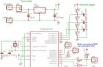
Fig.1. Schematic diagram of the generator set.
U f1 - U f3 - voltage in the phase windings: U d - rectified voltage; 1, 2, 3 - windings of three stator phases: 4 - power rectifier diodes; 5 - battery; 6 - load; 7 - diodes of the rectifier of the excitation winding; 8 - excitation winding; 9 - voltage regulator
When connected to a "delta", the phase currents are 3 times less than the linear ones, while the "star" has the same linear and phase currents. This means that with the same current given off by the generator, the current in the phase windings, when connected to a "triangle", is much less than that of a "star". Therefore, in high-power generators, a delta connection is often used, since at lower currents, the windings can be wound with a thinner wire, which is more technologically advanced. However, the linear voltages at the "star" to the root of 3 are greater than the phase voltage, while at the "triangle" they are equal and to obtain the same output voltage, at the same speeds, the "triangle" requires a corresponding increase in the number of turns of its phases compared to "star".
A thinner wire can also be used with a star connection. In this case, the winding is made of two parallel windings, each of which is connected into a "star", i.e., a "double star" is obtained.
The rectifier for a three-phase system contains six power semiconductor diodes, three of which: VD1, VD3 and VD5 are connected to the "+" terminal of the generator, and the other three: VD2, VD4 and VD6 are connected to the "-" ("ground"). If it is necessary to boost the generator power, an additional rectifier arm based on diodes VD7, VD8 is used, shown in Fig. 1, dotted line. Such a rectifier circuit can only take place when the stator windings are connected to a "star", since the additional arm is powered from the "zero" point of the "star".
For a significant number of types of generators from foreign companies, the field winding is connected to its own rectifier, assembled on VD9-VD 11 diodes. Such a connection of the field winding prevents the battery discharge current from flowing through it when the car engine is not running. Semiconductor diodes are in the open state and do not provide significant resistance to the passage of current when a voltage is applied to them in the forward direction and practically do not pass current when the reverse voltage is applied. According to the phase voltage graph (see Fig. 1), you can determine which diodes are open and which are closed at the moment. Phase voltages U f1 acts in the winding of the first phase, U f2 - the second, U f3 - the third. These voltages change along curves close to a sinusoid and at some points in time they are positive, at others they are negative. If the positive direction of the voltage in the phase is taken along the arrow directed to the zero point of the stator winding, and negative from it, then, for example, for the time t 1, when the voltage of the second phase is absent, the first phase is positive, and the third is negative. The direction of phase voltages corresponds to the arrows shown in fig. 1. Current through the windings, diodes and load will flow in the direction of these arrows. At the same time, diodes VD1 and VD4 are open. Having considered any other moments of time, it is easy to verify that in a three-phase voltage system that occurs in the generator phase windings, the power rectifier diodes go from open to closed and vice versa in such a way that the current in the load has only one direction - from the "+" terminal of the generator set to its output "-" ("mass"), i.e., a direct (rectified) current flows in the load. The rectifier diodes of the excitation winding work in a similar way, supplying this winding with a rectified current. Moreover, the excitation winding rectifier also includes 6 diodes, but three of them VD2, VD4, VD6 are common with the power rectifier. So at time t 1, diodes VD4 and VD9 are open, through which the rectified current enters the excitation winding. This current is much less than the current supplied by the generator to the load. Therefore, small-sized low-current diodes for a current of not more than 2 A are used as VD9-VD11 diodes (for comparison, power rectifier diodes allow currents up to 25 ... 35 A to flow).
It remains to consider the principle of operation of the rectifier arm containing diodes VD7 and VD8. If the phase voltages were purely sinusoidal, these diodes would not participate at all in the process of converting AC to DC. However, in real generators, the shape of the phase voltages differs from a sinusoid. It is a sum of sinusoids, which are called harmonic components or harmonics - the first, the frequency of which coincides with the frequency of the phase voltage, and the higher ones, mainly the third, whose frequency is three times higher than the first. The representation of the real form of the phase voltage as a sum of two harmonics (first and third) is shown in Fig.2. It is known from electrical engineering that in the linear voltage, i.e., in the voltage that is supplied to the rectifier and rectified, the third harmonic is absent. This is due to the fact that the third harmonics of all phase 
Fig.2. Representation of the phase voltage U f as the sum of the sinusoids of the first, U 1, and third U 3, harmonicsvoltages are in phase, that is, they simultaneously reach the same values and at the same time mutually balance and cancel each other out in a linear voltage. Thus, the third harmonic is present in the phase voltage, but not in the linear one. Consequently, the power developed by the third harmonic of the phase voltage cannot be used by consumers. To use this power, diodes VD7 and VD8 are added, connected to the zero point of the phase windings, i.e. to the point where the effect of the phase voltage is affected. Thus, these diodes only rectify the third harmonic voltage of the phase voltage. The use of these diodes increases the generator power by 5...15% at a speed of more than 3000 min-1.
The rectified voltage, as shown in Fig. 1, is pulsating. These ripples can be used to diagnose the rectifier. If the ripples are identical, the rectifier is working normally, but if the picture on the oscilloscope screen has a symmetry violation, the diode may fail. This check should be done with the battery disconnected. You should pay attention to the fact that the term "rectifier diode" does not always hide the usual design that has a case, leads, etc. sometimes it's just a semiconductor silicon junction sealed on a heat sink.
The use of electronics and especially microelectronics in the voltage regulator, i.e. the use of field-effect transistors or the implementation of the entire voltage regulator circuit on a silicon single crystal, required the introduction of elements to protect it from high voltage surges in the generator set, which occur, for example, when the battery is suddenly disconnected, load shedding. Such protection is ensured by the fact that the power bridge diodes are replaced by zener diodes. The difference between a zener diode and a rectifier diode is that when a voltage is applied to it in the opposite direction, it does not pass current only up to a certain value of this voltage, called the stabilization voltage. Usually, in power zener diodes, the stabilization voltage is 25 ... 30 V. When this voltage is reached, the zener diodes "break through", that is, they begin to pass current in the opposite direction, and within certain limits of the change in the strength of this current, the voltage on the zener diode, and, therefore, and at the output "+" of the generator remains unchanged, not reaching values \u200b\u200bdangerous for electronic components. The property of a zener diode to maintain a constant voltage at its terminals after a "breakdown" is also used in voltage regulators.
Generator device
According to their design, generator sets can be divided into two groups - generators of traditional design with a fan at the drive pulley and generators of the so-called compact design with two fans in the internal cavity of the generator. Usually "compact" generators are equipped with a drive with an increased gear ratio through a V-ribbed belt and therefore, according to the terminology adopted by some companies, they are called high-speed generators. At the same time, within these groups, generators can be distinguished, in which the brush assembly is located in the internal cavity of the generator between the pole system of the rotor and the rear cover, and generators, where slip rings and brushes are located outside the internal cavity. In this case, the generator has a casing, under which there is a brush assembly, a rectifier and, as a rule, a voltage regulator.
Any generator contains a stator with a winding, sandwiched between two covers - the front, on the drive side, and the rear, on the side of the slip rings. The covers, cast from aluminum alloys, have ventilation windows through which air is blown by a fan through the generator.
Generators of traditional design are equipped with ventilation windows only in the end part, generators of "compact" design are also on the cylindrical part above the front sides of the stator winding. The "compact" design is also distinguished by highly developed ribbing, especially in the cylindrical part of the covers. A brush assembly, which is often combined with a voltage regulator, and a rectifier assembly are attached to the cover from the side of the slip rings. The covers are usually tightened together by three or four screws, and the stator is usually sandwiched between the covers, the seating surfaces of which cover the stator along the outer surface. Sometimes the stator is completely recessed in the front cover and does not rest against the back cover, there are designs in which the middle sheets of the stator pack protrude above the rest and they are a seat for the covers. The mounting legs and tension eye of the generator are cast together with the covers, moreover, if the fastening is two-legged, then the legs have both covers, if it is single-legged, only the front one. However, there are designs in which a single-leg fastening is carried out by joining the tides of the back and front covers, as well as two-leg fastenings, in which one of the legs, made of stamped steel, is screwed to the back cover, as, for example, in some of the Paris-Rhone generators of the previous issues. With a two-arm mount, a distance sleeve is usually located in the hole of the rear leg, which allows you to select the gap between the engine bracket and the leg seat when installing the generator. The hole in the tension ear can be one with or without thread, but there are also several holes, which makes it possible to install this generator on different brands of engines. For the same purpose, two tension ears are used on one generator.

Fig.31 - core, 2 - winding, 3 - grooved wedge, 4 - groove, 5 - output for connection with a rectifier
The generator stator (Fig. 3) is made of steel sheets with a thickness of 0.8 ... 1 mm, but more often it is wound "on edge". This design provides less waste during processing and high manufacturability. When the stator package is made by winding, the stator yoke usually has protrusions above the grooves, along which the position of the layers relative to each other is fixed during winding. These protrusions improve the cooling of the stator due to its more developed outer surface. The need to save metal also led to the creation of a stator package design, assembled from separate horseshoe-shaped segments. The fastening between the individual sheets of the stator package into a monolithic structure is carried out by welding or rivets. Almost all mass-produced car generators have 36 slots in which the stator winding is located. The grooves are insulated with film insulation or sprayed with epoxy compound.

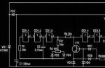
Fig.4A - loop distributed, B - wave concentrated, C - wave distributed
------- 1 phase, - - - - - - 2 phase, -..-..-..- 3 phase
In the grooves there is a stator winding, performed according to the schemes (Fig. 4) in the form of a distributed loop (Fig. 4, A) or wave concentrated (Fig. 4, B), wave distributed (Fig. 4, C) windings. The loop winding is characterized by the fact that its sections (or half-sections) are made in the form of coils with frontal connections on both sides of the stator package opposite each other. The wave winding really resembles a wave, since its frontal connections between the sides of the section (or half-section) are alternately located on one or the other side of the stator package. For a distributed winding, the section is divided into two half-sections coming from one groove, with one half-section going to the left, the other to the right. The distance between the sides of the section (or half-section) of each phase winding is 3 groove divisions, i.e. if one side of the section lies in the groove conventionally taken as the first one, then the second side fits into the fourth groove. The winding is fixed in the groove with a groove wedge made of insulating material. It is obligatory to impregnate the stator with varnish after laying the winding.
A feature of automotive generators is the type of the pole system of the rotor (Fig. 5). It contains two pole halves with protrusions - beak-shaped poles, six on each half. The pole halves are made by stamping and may have protrusions - half-bushings. In the absence of protrusions, when pressing onto the shaft, a bushing with an excitation winding wound on the frame is installed between the pole halves, while the winding is carried out after the bushing is installed inside the frame.

Fig.5. The rotor of the automobile generator: a - assembled; b - disassembled pole system; 1.3-pole halves; 2 - excitation winding; 4 - contact rings; 5 - shaft
If the pole halves have half bushings, then the excitation winding is preliminarily wound on the frame and installed when pressing the pole halves so that the half bushings enter the frame. End cheeks of the frame have latch protrusions that enter the interpolar gaps at the ends of the pole halves and prevent the frame from turning on the sleeve. Pressing the pole halves onto the shaft is accompanied by their caulking, which reduces the air gaps between the bushing and the pole halves or half bushings, and has a positive effect on the output characteristics of the generator. When caulking, the metal flows into the grooves of the shaft, which makes it difficult to rewind the excitation winding when it burns out or breaks, since the rotor pole system becomes difficult to disassemble. The excitation winding assembled with the rotor is impregnated with varnish. The beaks of the poles are usually bevelled at the edges on one or both sides to reduce the magnetic noise of the generators. In some designs, for the same purpose, an anti-noise non-magnetic ring is placed under the sharp cones of the beaks, located above the excitation winding. This ring prevents the beaks from oscillating when the magnetic flux changes and, therefore, from emitting magnetic noise.
After assembly, the dynamic balancing of the rotor is performed, which is carried out by drilling out excess material at the pole halves. On the rotor shaft there are also contact rings, most often made of copper, with plastic crimping. The excitation winding leads are soldered or welded to the rings. Sometimes the rings are made of brass or stainless steel, which reduces wear and oxidation, especially when working in a humid environment. The diameter of the rings when the brush-contact assembly is located outside the inner cavity of the generator cannot exceed the inner diameter of the bearing installed in the cover from the side of the slip rings, because during assembly the bearing passes over the rings. The small diameter of the rings also helps to reduce brush wear. It is for the installation conditions that some companies use roller bearings as the rear support of the rotor, because. ball bearings of the same diameter have a shorter resource.
The rotor shafts are made, as a rule, from mild free-cutting steel, however, when using a roller bearing, the rollers of which operate directly at the end of the shaft from the side of the slip rings, the shaft is made of alloyed steel, and the shaft pin is cemented and hardened. At the threaded end of the shaft, a groove is cut for the key for attaching the pulley. However, in many modern designs, the key is missing. In this case, the end part of the shaft has a recess or a turnkey protrusion in the form of a hexagon. This helps to keep the shaft from turning when tightening the pulley nut, or during disassembly, when it is necessary to remove the pulley and fan.
The brush assembly is a plastic structure that houses the brushes i.e. sliding contacts. Two types of brushes are used in automotive alternators - copper graphite and electrographite. The latter have an increased voltage drop in contact with the ring in comparison with copper-graphite ones, which adversely affects the output characteristics of the generator, but they provide much less wear of slip rings. The brushes are pressed against the rings by the force of the springs. Typically, brushes are mounted along the radius of slip rings, but there are also so-called reactive brush holders, where the brush axis forms an angle with the ring radius at the brush contact point. This reduces the friction of the brush in the guides of the brush holder and thus ensures a more reliable contact of the brush with the ring. Often the brush holder and voltage regulator form a non-separable single unit.
Rectifier units are used of two types - either these are heat sink plates into which power rectifier diodes are pressed (or soldered) or on which silicon junctions of these diodes are soldered and sealed, or these are structures with highly developed finning, in which diodes, usually tablet-type, are soldered to heat sinks. The diodes of the additional rectifier usually have a plastic case of a cylindrical shape or in the form of a pea, or they are made in the form of a separate sealed unit, the inclusion in the circuit of which is carried out by busbars. The inclusion of rectifier units in the generator circuit is carried out by soldering or welding the phase leads on special mounting pads of the rectifier or by screws. The most dangerous for the generator, and especially for the wiring of the automotive on-board network, is the bridging of the heat sink plates connected to the “ground” and the “+” terminal of the generator with metal objects that accidentally fall between them or conductive bridges formed by pollution, tk. this causes a short circuit in the battery circuit and a fire is possible. To avoid this, the plates and other parts of the rectifier generators of some companies are partially or completely covered with an insulating layer. In a monolithic design of the rectifier unit, heat sinks are mainly combined with mounting plates made of insulating material, reinforced with connecting bars.
Generator bearing units are typically deep groove ball bearings with one-time grease lubrication for life and single or double sided seals built into the bearing. Roller bearings are used only on the side of the slip rings and quite rarely, mainly by American companies. The fit of ball bearings on the shaft from the side of the slip rings is usually tight, from the drive side - sliding, in the seat of the cover, on the contrary - from the side of the slip rings - sliding, from the drive side - tight. Since the outer race of the bearing on the side of the slip rings has the ability to rotate in the seat of the cover, the bearing and cover may soon fail, the rotor will touch the stator. To prevent the bearing from turning, various devices are placed in the seat of the cover - rubber rings, plastic cups, corrugated steel springs, etc.

Fig.6. Bosch voltage regulators of various designs.
a - on discrete elements; b - hybrid installation; c - scheme on a single crystal of silicon.
1 - power output stage, 2 - control circuit
The design of voltage regulators is largely determined by the technology of their manufacture. When manufacturing a circuit on discrete elements, the regulator usually has a printed circuit board on which these elements are located. At the same time, some elements, for example, tuning resistors, can be made using thick-film technology. Hybrid technology assumes that resistors are made on a ceramic plate and connected to semiconductor elements - diodes, zener diodes, transistors, which are soldered on a metal substrate in a frameless or packaged version. In a regulator made on a silicon single crystal, the entire regulator circuit is located in this crystal. Figure 6 shows the development of Bosch voltage regulators, which include all of the above designs. Hybrid voltage regulators and single-crystal voltage regulators are not subject to disassembly or repair.
The generator is cooled by one or two fans mounted on its shaft. In this case, in the traditional design of generators (Fig. 7, a), air is sucked in by a centrifugal fan into the cover from the side of the slip rings. For generators with a brush assembly, a voltage regulator and a rectifier outside the internal cavity and protected by a casing, air is sucked in through the slots in this casing, directing air to the most heated places - to the rectifier and voltage regulator. On cars with a dense layout of the engine compartment, in which the air temperature is too high, generators with a special casing (Fig. 7, b) are used, fixed on the back cover and equipped with a branch pipe with a hose through which cold and clean outside air enters the generator. Such designs are used, for example, on BMW cars. For "compact" generators, cooling air is taken from both the rear and front covers.

Fig.7. Generator cooling system.
a - generators of conventional design; b - generators for elevated temperatures in the engine compartment; c - compact design generators.
The arrows show the direction of air flow
Large power generators installed on special vehicles, trucks and buses have some differences. In particular, they have two pole systems of the rotor mounted on one shaft and, consequently, two excitation windings, 72 slots on the stator, etc. However, there are no fundamental differences in the design of these generators from the structures considered.
Characteristics of generating sets
The ability of the generator set to provide consumers with electricity in various engine operating modes is determined by its current-speed characteristic (TLC) - the dependence of the maximum current output by the generator on the rotor speed at a constant voltage at the power outputs. On fig. 1 shows the current-speed characteristic of the generator.
Rice. 1. Current-speed characteristic of generator sets.
The graph contains the following characteristic points:
n 0 - initial rotor speed without load, at which the generator starts to give current;
I xd - generator recoil current at a speed corresponding to the minimum stable idle speed of the engine. On modern generators, the current given in this mode is 40-50% of the nominal;
I dm is the maximum (rated) output current at a rotor speed of 5000 min "" (6000 min "" for modern generators).
There are TLC determined:
In the technical documentation for generators, not all TLC is often indicated,with self-excitation (the excitation winding circuit is powered by its own generator); with independent excitation (the excitation winding circuit is powered by an external source); for a generator set (a voltage regulator is included in the circuit); for the generator (voltage regulator is disabled); in a cold state (cold is understood as a state in which the temperature of the generator nodes is practically equal to the ambient air temperature (25 ± 10) ° C, since the generator heats up during the experimental determination of TLC, the experiment time should be minimal, i.e. no more than 1 min , and the experiment should be repeated after the temperature of the nodes again becomes equal to the ambient air temperature); in a heated state.
but only its individual characteristic points (see Fig. 1).
These points include:
How to define the parameters of your generator:initial speed at idle n 0 . It corresponds to the set voltage of the generator without load; the greatest current given by the generator I dm. (Automobile valve generators are self-limiting, i.e., having reached the force I dm, the value of which is close to the value of the short-circuit current, the generator, with a further increase in the speed of rotation, cannot give consumers a larger current. The current I dm multiplied by the rated voltage determines the rated power automotive generators); rotation speed n pn and current strength I dn in the design mode. (The design mode point is determined at the point where the TLC touches the tangent drawn from the origin. Approximately, the calculated value of the current strength can be determined as 0.67 I dm an increase in the rotation frequency increases the current of the generator and, consequently, the heating of its nodes, but at the same time the intensity of cooling of the generator by a fan located on its shaft increases. rotational speed n xd and current strength I xd in the mode corresponding to the idling of the internal combustion engine (ICE). In this mode, the generator must provide the current strength necessary to power a number of important consumers, primarily ignition in carburetor internal combustion engines.
For domestic generators: For new models of domestic engines (VAZ-2111, 2112, ZMZ-406, etc.): compact design generators (94.3701, etc.) are installed. Brushless (inductor) generators (955.3701 for VAZs, G700A for UAZs) differ from the traditional design in that they have permanent magnets on the rotor, and excitation windings on the stator (mixed excitation). This made it possible to do without a brush assembly (a vulnerable part of the generator) and slip rings. However, these generators have a slightly larger mass and a higher noise level.
On the shield of the generator, its main parameters are usually indicated:
The main characteristic of the generator set is its current-speed characteristic (TLC), i.e., the dependence of the current supplied by the generator to the network on the speed of its rotor at a constant voltage at the power outputs of the generator.
This characteristic is determined when the generator set is operating, complete with a fully charged battery with a nominal capacity expressed in A / h, which is at least 50% of the generator rated current. The characteristic can be determined in the cold and heated states of the generator. In this case, the cold state is understood as such, in which the temperature of all parts and assemblies of the generator is equal to the ambient temperature, the value of which should be 23±5°C. The air temperature is determined at a point at a distance of 5 cm from the generator air intake. Since the generator heats up during the characterization due to the power losses released in it, it is methodically difficult to record TLC in a cold state and most companies give current-speed characteristics of generators in a heated state, i.e. in a state in which the components and parts of the generator are heated in each determined point to a steady value due to the power losses generated in the generator at the above cooling air temperature.
The range of change in the speed of rotation during the removal of the characteristics is between the minimum frequency at which the generator set develops a current of 2A (about 1000 min -1) and the maximum. Characterization is carried out with an interval of 500 to 4000 min -1 and 1000 min -1 at higher frequencies. Some companies provide current-speed characteristics determined at rated voltage, i.e. at 14 V, typical for cars. However, it is possible to remove such characteristics only with a regulator specially rebuilt for a high level of voltage maintenance. To prevent the operation of the voltage regulator when removing the current-speed characteristic, it is determined at voltages U t \u003d 13.5 ± 0.1 V for a 12-volt on-board system. An accelerated method for determining the current-speed characteristic is also allowed, requiring a special automated stand, in which the generator warms up for 30 minutes at a speed of 3000 min -1 corresponding to this frequency, current strength and the voltage indicated above. Characterization time should not exceed 30 s at constantly changing speed.
The current-speed characteristic has characteristic points, which include:
n 0 - initial speed without load. Since the characterization usually begins with the load current (about 2A), this point is obtained by extrapolating the characterization taken to the intersection with the x-axis.
n L is the minimum operating speed, i.e., the speed approximately corresponding to the idle speed of the engine. Conditionally accepted, n L = 1500 min -1 . This frequency corresponds to the current I L . Firm Bosch for "compact" generators took n L =1800 min -1 . Usually I L is 40...50% of the rated current.
n R - rated speed at which the rated current I R is generated. This speed is taken n R = 6000 min -1 . I R - the smallest current that the generator set must produce at a speed of rotation n R .
N MAX - maximum speed. At this speed, the generator produces the maximum current I max. Usually, the maximum current differs little from the nominal I R (no more than 10%).
Manufacturers provide in their information materials mainly only the characteristic points of the current-speed characteristic. However, for generator sets of passenger cars, with a sufficient degree of accuracy, it is possible to determine the current-speed characteristic by the known nominal value of the current I R and the characteristic according to Fig. 8, where the values of the generator current are given in relation to its nominal value.
In addition to the current-speed characteristic, the generator set is also characterized by the frequency of self-excitation. When the generator is running on a car complete with a storage battery, the generator set must be self-excited at an engine speed less than its idling speed. In this case, of course, the circuit must include a lamp for monitoring the operable state of the generator set with a power specified for it by the manufacturer of the generator and parallel resistors to it, if they are provided by the circuit.
Another characteristic by which it is possible to present the energy capabilities of the generator, i.e., to determine the amount of power taken by the generator from the engine, is the value of its coefficient of performance (COP), determined in the modes corresponding to the points of the current-speed characteristic (Fig. 8), the value of the efficiency according to fig.8 is given for orientation, because it depends on the design of the generator - the thickness of the plates from which the stator is assembled, the diameter of slip rings, bearings, winding resistance, etc., but mainly on the power of the generator. The more powerful the generator, the higher its efficiency.

Fig.8
Output characteristics of automotive generators:
1 - current-speed characteristic, 2 - efficiency by points of the current-speed characteristic
Finally, the generator set is characterized by the range of its output voltage, when the speed, load current and temperature change within certain limits. Usually, company brochures indicate the voltage between the power output "+" and the "mass" of the generator set at the control point or the regulator setting voltage when the generator set is cold at a speed of 6000 min -1, a current load of 5 A and operation complete with a storage battery, as well as thermal compensation - a change in the regulated voltage depending on the ambient temperature. Thermal compensation is indicated as a coefficient characterizing the change in voltage when the ambient temperature changes by ~1°C. As shown above, as the temperature rises, the generator set voltage decreases. For passenger cars, some companies offer generator sets with the following regulator settings and thermal compensation:
Setting voltage, V .............................. 14.1±0.1 14.5+0, 1
Thermal compensation, mV/°С............................... -7+1.5 -10±2
Generator Options.
The following notations are used in the table: P max - maximum output power, U nom - rated voltage, I max - maximum output current at maximum rotor speed (for most generators, 6000 rpm is taken as maximum speed), N o - initial excitation frequency generator (I \u003d 0), N r - generator speed in the design mode, I r - current strength in the design mode.Thus, knowing the initial excitation frequency and current at this frequency, the final frequency and maximum current, as well as one intermediate value, it is possible to build a fairly accurate three-point TLC of the generator.
| Marking | Application | Pmax, W. (U nom, V) |
N o , min -1 | I pH, A | N pH, min -1 | I max , A | Excitation |
| G502A | ZAZ-968M LuAZ-969M |
420 (14) | 1500 | 20 | 3200 | 30 | self-excitation |
| G250 and modifications | M412 M427 UAZ ZIL-131 ZIL-157 ZIL-130 |
500 (12) | 950 | 28 | 2100 | 40 | independent |
| G221A and modifications | VAZ-2101 VAZ-21011 VAZ-2103 VAZ-2106 VAZ-2121 |
600 (14) | 1150 | 30 | 2500 | 42 | self |
| G222 | VAZ-2104 VAZ-2105 VAZ-2107 VAZ-1111 ZAZ-1102 M2141 |
700 (14) | 1250 | 35 | 2400 | 50 | self |
| 16.3701 and modifications | GAZ-2410 RAF-2203-01 GAZ-31029 GAZ-3102 |
900 (14) | 1100 | 45 | 2500 | 65 | self |
| 16.3771 | UAZ | 800 (14) | 1000 | 40 | 2050 | 57 | self |
| 17.3701 | ZIL-425850 ZIL-157 |
500 (14) | 1000 | 24 | 2000 | 40 | independent |
| 19.3701 | 1260 (14) | 1050 | 60 | 2150 | 90 | self | |
| 19.3771 | GAZ-3102 GAZ-31029 GAZ-3110 |
940 (14) | 800 | 45 | 2200 | 67 | |
| 25.3771 | GAZ-3110 | 1120 (14) | 1100 | 53 | 2200 | 80 | self |
| 26.3771 | VAZ-2104 VAZ-2105 VAZ-2108 VAZ-2109 |
940 (14) | 800 | 45 | 2200 | 67 | |
| 29.3701 | M2140 M412 IZH-2125 IZH-2715 |
700 (14) | 1250 | 32 | 2250 | 50 | self |
| 32.3701 | ZIL-130 ZIL-157 |
840 (14) | 1050 | 40 | 2200 | 60 | self |
| 37.3701 | VAZ-2108 VAZ-2109 VAZ-21213 M2141 |
770 (14) | 1100 | 35 | 2000 | 55 | self |
| 38.3701 and modifications | ZIL-4331 ZIL-133GYA |
1330 (14) | 900 | 60 | 1800 | 95 | independent |
| 45.3701 | 630 (14) | 1100 | 28 | 2000 | 45 | self | |
| 58.3701 | M2140 M2141 M412 IZH-2125 IZH-2715 |
730 (14) | 1400 | 32 | 2400 | 52 | self |
| 63.3701 | BelAZ | 4200 (28) | 1500 | 150 | 2500 | 150 | self |
| 65.3701 | LAZ-42021 LiAZ-5256 |
2500 (28) | 1250 | 60 | 2400 | 90 | |
| 66.3701 | PAZ-672M PAZ-3201 |
840 (14) | 1150 | 40 | 2600 | 60 | |
| 94.3701 | GAZ-3302 VAZ-2110 |
1000 (14) | 900 | 40 | 1800 | 70 | self |
| 851.3701 | ZIL-53012 | 1150 (14) | 1200 | 55 | 3000 | 82 | |
| 9002.3701 | ZIL-4334 | 2240 (28) | 1350 | 53 | 2600 | 80 | |
| G254 | 560 (14) | 1100 | 28 | 2350 | 40 | independent | |
| G266 and modifications | 840 (14) | 1250 | 40 | 2750 | 60 | self | |
| G286 | 1200 (14) | 900 | 63 | 1700 | 85 | independent | |
| G273 and modifications | KAMAZ-5320 MAZ-5335 |
780 (28) | 1100 | 20 | 2200 | 28 | independent |
| G289 and modifications | 2200 (28) | 1250 | 60 | 2400 | 80 | self | |
| G263A,B | 4200 (28) | 1500 | 80 | 2500 | 150 | self | |
| 955.3701 brushless |
VAZ-2108 VAZ-2109 |
900 (14) | 1050 | 50 | 2800 | 65 | self |
| 583.3701 | ZAZ-1102 VAZ-2108 VAZ-2109 |
740 (14) | 1400 | 40 | 2500 | 53 | self |
Wiring diagrams for generating sets

 Rice. 2. Schemes of generator sets.
1 - generator;
2 - generator stator winding;
3 - excitation winding of the generator;
4 - power rectifier;
5 - voltage regulator;
6.8 - resistors in the generator health monitoring system;
7 - additional excitation winding rectifier;
9 - lamp for monitoring the generator's performance;
10 - ignition lock;
11 - capacitor;
12 - battery
 The option of connecting the excitation winding to the vehicle's on-board network and the deviation of the voltage level during operation depend on the electrical circuit of the generator set. The connection of the generator with the voltage regulator and the elements for monitoring the generator's performance is carried out mainly according to the diagrams shown in Fig. 2. The terminal designations in diagrams 1 and 2 correspond to those adopted by BOSCH, and 3 - to NIPPON DENSO. However, other firms may use different designations.
Scheme 1 is used most widely, especially on European-made cars Volvo, Audi, Mercedes, Opel, BMW, etc. Depending on the type of generator, its power, manufacturer, and especially on the time of its release, the power rectifier may not contain an additional rectifier arm, connected to the zero point of the stator winding, i.e. have not 8, but 6 diodes, be assembled on power zener diodes as shown in diagram 3.
Generator drive
The drive of generators is carried out from a pulley of a cranked shaft by a belt drive. The larger the diameter of the pulley on the crankshaft and the smaller the diameter of the generator pulley (the diameter ratio is called the gear ratio), the higher the generator speed, respectively, it is able to give more current to consumers.V-belt drive is not applicable for gear ratios greater than 1.7-3. First of all, this is due to the fact that with small diameter pulleys, the V-belt wears out intensively.
On modern models, as a rule, the drive is carried out by a V-ribbed belt. Due to its greater flexibility, it allows you to install a small diameter pulley on the generator and, consequently, to obtain higher gear ratios, that is, the use of high-speed generators. The tension of the V-ribbed belt is carried out, as a rule, by tension rollers with a stationary generator.
Mounting generators
Generators are bolted to the front of the engine on special brackets. The fixing feet and tension eye of the generator are located on the covers. If fastening is carried out by two paws, then they are located on both covers, if there is one paw, it is located on the front cover. In the hole of the rear leg (if there are two mounting legs), there is usually a spacer bushing that eliminates the gap between the engine bracket and the leg seat.Regulators maintain the generator voltage within certain limits for optimal operation of electrical appliances included in the vehicle's on-board network. All voltage regulators have measuring elements, which are voltage sensors, and actuating elements that regulate it.
In vibration controllers, the measuring and actuating element is an electromagnetic relay. For contact-transistor controllers, the electromagnetic relay is located in the measuring part, and the electronic elements are in the actuating part. These two types of regulators are now completely superseded by electronic ones.
Semiconductor non-contact electronic regulators are usually built into the generator and combined with a brush assembly. They change the excitation current by changing the time the rotor winding is switched on to the supply network. These regulators are not subject to misalignment and do not require any maintenance, except for checking the reliability of the contacts.
Voltage regulators have the property of thermal compensation - changing the voltage supplied to the battery, depending on the air temperature in the engine compartment for optimal battery charging. The lower the air temperature, the more voltage must be supplied to the battery and vice versa. The value of thermal compensation reaches up to 0.01 V per 1°C. Some models of remote regulators (2702.3702, РР-132А, 1902.3702 and 131.3702) have stepped manual voltage level switches (winter/summer).
The principle of operation of the voltage regulator.
Currently, all generator sets are equipped with solid-state electronic voltage regulators, usually built into the generator. Schemes of their execution and design may be different, but the principle of operation for all regulators is the same. The voltage of a generator without a regulator depends on the speed of its rotor, the magnetic flux created by the excitation winding, and, consequently, on the current strength in this winding and the amount of current given by the generator to consumers. The higher the rotational speed and the excitation current, the greater the generator voltage, the greater the load current, the lower this voltage.
The function of the voltage regulator is to stabilize the voltage when the speed and load change due to the effect on the excitation current. Of course, you can change the current in the excitation circuit by introducing an additional resistor into this circuit, as was done in the previous vibration voltage regulators, but this method is associated with power loss in this resistor and is not used in electronic regulators. Electronic regulators change the excitation current by turning on and off the excitation winding from the mains, while changing the relative duration of the turn-on time of the excitation winding. If it is necessary to reduce the excitation current to stabilize the voltage, the turn-on time of the excitation winding decreases, if it is necessary to increase it, it increases.
It is convenient to demonstrate the principle of operation of an electronic regulator using a fairly simple diagram of an EE 14V3 type regulator from Bosch, shown in fig. 9:

Fig.9
BOSCH EE14V3 voltage regulator circuit:
1 - generator, 2 - voltage regulator, SA - ignition lock, HL - control lamp on the instrument panel.
To understand the operation of the circuit, it should be remembered that, as shown above, the zener diode does not pass current through itself at voltages below the stabilization voltage. When the voltage reaches this value, the zener diode “breaks through” and current begins to flow through it. Thus, the zener diode in the regulator is the voltage standard with which the generator voltage is compared. In addition, it is known that transistors pass current between the collector and emitter, i.e. are open if current flows in the "base-emitter" circuit, and do not let this current through, i.e. closed if the base current is interrupted. The voltage to the zener diode VD2 is supplied from the output of the generator "D +" through a voltage divider on resistors R1 (R3 and the diode VD1, which performs temperature compensation. While the generator voltage is low and the voltage on the zener diode is lower than its stabilization voltage, the zener diode is closed through it, and, therefore, and no current flows in the base circuit of the transistor VT1, the transistor VT1 is also closed.In this case, the current through the resistor R6 from the output "D +" enters the base circuit of the transistor VT2, which opens, through its emitter-collector junction current begins to flow in the base of the transistor VT3 , which also opens.In this case, the excitation winding of the generator is connected to the power circuit through the emitter-collector junction VT3.
The connection of transistors VT2 and VT3, in which their collector terminals are combined, and the base circuit of one transistor is powered from the emitter of the other, is called the Darlington circuit. With this connection, both transistors can be considered as one compound transistor with a large gain. Typically, such a transistor is made on a single silicon crystal. If the generator voltage has increased, for example, due to an increase in the rotational speed of its rotor, then the voltage at the zener diode VD2 also increases, when this voltage reaches the stabilization voltage value, the zener diode VD2 “breaks through”, the current through it begins to flow into the base circuit of the transistor VT1, which the emitter-collector junction opens and short-circuits the output of the base of the composite transistor VT2, VT3 to ground. The composite transistor closes, breaking the power supply circuit of the excitation winding. The excitation current drops, the generator voltage decreases, the zener diode VT2, the transistor VT1 close, the composite transistor VT2, VT3 opens, the excitation winding is reconnected to the power circuit, the generator voltage increases and the process repeats. Thus, the regulation of the generator voltage by the regulator is carried out discretely through a change in the relative time of switching on the excitation winding in the power circuit. In this case, the current in the excitation winding changes as shown in Fig. 10. If the generator speed has increased or its load has decreased, the winding turn-on time is reduced, if the speed has decreased or the load has increased, it increases. In the regulator circuit (see Fig. 9) there are elements characteristic of the circuits of all voltage regulators used on cars. The diode VD3, when closing the composite transistor VT2, VT3, prevents dangerous voltage surges that occur due to an open circuit of the excitation winding with significant inductance. In this case, the field winding current can be closed through this diode and dangerous voltage surges do not occur. Therefore, the VD3 diode is called quenching. The resistance R7 is a hard feedback resistance.

Fig.10. The change in the current strength in the excitation winding J B over time t during the operation of the voltage regulator: t on, t off - respectively, the time of turning on and off the excitation winding of the voltage regulator; n 1 n 2 - generator rotor speed, and n 2 is greater than n 1 ; J B1 and J B2 - average current in the field winding
When the composite transistor VT2, VT3 is opened, it turns out to be connected in parallel with the resistance R3 of the voltage divider, while the voltage at the zener diode VT2 decreases sharply, this speeds up the switching of the regulator circuit and increases the frequency of this switching, which has a beneficial effect on the quality of the generator set voltage. Capacitor C1 is a kind of filter that protects the regulator from the influence of voltage pulses at its input. In general, capacitors in the regulator circuit either prevent the transition of this circuit into an oscillatory mode and the possibility of extraneous high-frequency interference from affecting the operation of the regulator, or accelerate the switching of transistors. In the latter case, the capacitor, being charged at one moment of time, is discharged to the base circuit of the transistor at another moment, accelerating the switching of the transistor by a surge of the discharge current and, consequently, reducing its heating and energy losses in it.
Figure 9 clearly shows the role of the lamp HL for monitoring the operable state of the generator set (charge control lamp on the dashboard of the car). With the vehicle engine off, closing the contacts of the ignition switch SA allows current from the battery GA to flow through this lamp into the excitation winding of the generator. This ensures the initial excitation of the generator. At the same time, the lamp burns, signaling that there is no open circuit in the excitation winding circuit. After starting the engine, almost the same voltage appears at the generator terminals "D +" and "B +" and the lamp goes out. If the generator does not develop voltage when the car engine is running, then the HL lamp continues to burn in this mode, which is a signal of a generator failure or a broken drive belt. The introduction of a resistor R into the generator set helps to expand the diagnostic capabilities of the HL lamp. In the presence of this resistor, in the event of an open circuit in the excitation winding when the car engine is running, the HL lamp lights up. Currently, more and more companies are switching to the production of generator sets without an additional excitation winding rectifier. In this case, the generator phase output is connected to the regulator. When the car engine is not running, there is no voltage at the output of the generator phase and the voltage regulator in this case switches to a mode that prevents the battery from discharging to the excitation winding. For example, when the ignition switch is turned on, the regulator circuit switches its output transistor into an oscillatory mode, in which the current in the excitation winding is small and amounts to fractions of an ampere. After starting the engine, a signal from the generator phase output puts the regulator circuit into normal operation. In this case, the regulator circuit also controls the lamp for monitoring the operable state of the generator set.

Fig.11. Temperature dependence of the voltage maintained by the Bosch EE14V3 regulator at a speed of 6000 min -1 and a load current of 5A.
For its reliable operation, the storage battery requires that with a decrease in the temperature of the electrolyte, the voltage supplied to the battery from the generator set increases slightly, and decreases with an increase in temperature. To automate the process of changing the level of maintained voltage, a sensor is used, placed in the battery electrolyte and included in the voltage regulator circuit. But this is only for advanced cars. In the simplest case, the temperature compensation in the regulator is selected in such a way that, depending on the temperature of the cooling air entering the generator, the voltage of the generator set changes within the specified limits. Figure 11 shows the temperature dependence of the voltage maintained by the Bosch EE14V3 regulator in one of the operating modes. The graph also shows the tolerance field for the value of this voltage. The falling nature of the dependence ensures a good charge of the battery at a negative temperature and the prevention of enhanced boiling of its electrolyte at a high temperature. For the same reason, on cars designed specifically for operation in the tropics, voltage regulators are installed with a deliberately lower tuning voltage than for temperate and cold climates.
The operation of the generator set in different modes
When starting the engine, the main consumer of electricity is the starter, the current reaches hundreds of amperes, which causes a significant voltage drop at the battery terminals. In this mode, consumers of electricity are powered only by the battery, which is intensively discharged. Immediately after starting the engine, the generator becomes the main source of electricity. It provides the required current to charge the battery and operate electrical appliances. After recharging the battery, the difference between its voltage and the generator becomes small, which leads to a decrease in the charging current. The generator is still the source of power, and the battery smooths out the generator voltage ripples.When powerful consumers of electricity are turned on (for example, a rear window defroster, headlights, a heater fan, etc.) and a low rotor speed (low engine speed), the total current consumed may be greater than the generator is capable of delivering. In this case, the load will fall on the battery, and it will begin to discharge, which can be controlled by the readings of an additional voltage indicator or voltmeter.
Replacing one type of alternator on a vehicle with another is always possible if four conditions are met:When installing the battery in a vehicle, make sure the polarity is correct. The error will lead to the immediate failure of the generator rectifier, a fire may occur. The same consequences are possible when starting the engine from an external current source (lighting up) with the wrong connection polarity. When operating a car, you must:generators have the same current-speed characteristics or, in terms of energy indicators, the characteristics of the replacement generator are not worse than those of the replaced one; the gear ratio from the engine to the generator is the same; the overall and connecting dimensions of the replacement generator make it possible to install it on the engine. It should be borne in mind that most generators of foreign passenger cars have a single-legged mount, while domestic generators are mounted on the engine by two legs, so replacing a foreign generator with a domestic one will most likely require replacing the generator mounting bracket on the engine; the diagrams of the replacement and replacement generator sets are identical.
It is not allowed to perform the following actions:monitor the condition of the electrical wiring, especially the cleanliness and reliability of the connection of the contacts of the wires suitable for the generator, voltage regulator. With poor contacts, the on-board voltage may go beyond the permissible limits; disconnect all wires from the generator and from the battery during electric welding of car body parts; check the correct tension of the alternator belt. A loosely tensioned belt does not ensure the efficient operation of the generator, a tensioned one too much leads to the destruction of its bearings; immediately find out the cause of the ignition of the control lamp of the generator.
leave the car with the battery connected if you suspect a malfunction of the generator rectifier. This can lead to a complete discharge of the battery and even to a fire in the electrical wiring; check the operability of the generator by shorting its outputs to ground and to each other; check the serviceability of the generator by disconnecting the battery while the engine is running due to the possibility of failure of the voltage regulator, electronic elements of injection systems, ignition, on-board computer, etc.; allow electrolyte, "Tosol", etc. to get on the generator.
If we compare a car with a living organism, then its engine acts as a heart, and a generator acts as a nervous system. Will the car be able to move without this unit? Yes, it can, but not for long, not yet. It is the car alternator that charges the battery, maintaining the overall voltage of the working network. We will tell you about the principle of operation of the generator and its main elements.
How the unit is arranged

Rotor
This part, in fact, is an electromagnet with one winding. It is located on the shaft. A special core is attached over the winding, the diameter of which is one and a half to two millimeters less than the diameter of the starter. The current supply is provided by copper rings. They are also located on the shaft and are connected to the winding with special brushes.
Winding
The starter winding is made of copper wire. It is attached to the grooves of the core. The latter is made in the form of a circle and is made of metal with enhanced magnetic properties. This material is called transformer iron. Since the generator is three-phase, the starter is equipped with three windings. They are connected to each other and together resemble a triangle.
A rectifier bridge is connected at the point of their connection. The wire from which the winding is made is provided with double heat-resistant insulation. In most cases, a special varnish is used for this.
Relay-regulator
Another important element is the relay-regulator. It is an electronic circuit and has an output to graphite brushes. The relay-regulator can be installed in the generator housing or separately from it. In the first case, it is located next to the graphite brushes, and in the second, the brushes are attached to.
Rectifier bridge
The part is formed from six diodes. The latter are located on a conductive base in pairs and are combined with each other. At the output, the AC voltage is converted to DC. The bridge is also called a "horseshoe" due to the fact that outwardly it resembles this product.
On the video - the generator device:
The principle of operation of the generator
The operation of a car generator is based on the principle of education. This happens in the stator windings. The electrical voltage is generated due to the action of a constant magnetic field formed around the core. The motor drives the generator rotor by means of a belt drive. A constant voltage is applied to the winding, which is sufficient to create a magnetic flux.
When the core rotates along the windings, an electromotive force arises in them. The relay-regulator adjusts the strength of the magnetic flux in accordance with the load that is removed from the generator terminal. At the output, a voltage is formed in the range of 13.6–14.2 (this depends on the time of year). This is enough to recharge and keep it constantly charged. The on-board network is also powered by the positive terminal and is connected in parallel with the battery. Regardless of which generator you bought, the device and principle of operation will be the same for all samples. All such units work the same way.
On the video - the principle of operation of the generator:
Not a single car generator can work without. This element ensures that the constant voltage is maintained, which the unit generates due to the change in current strength that occurs in the windings. If the rotor rotates at a high frequency without a regulator, the voltage can reach a couple of tens of volts. This will lead to burnout of lamps and breakage of windings, diodes and other devices.
Regulator types
According to their design, voltage regulators are divided into two main categories:
- hybrid;
- integral.
The first group includes regulators, in the electronic circuit of which radio elements and are simultaneously used. In modern car models, integral regulators are most often used. All components of such devices (with the exception of the output stage) are made on the basis of thin-film microelectronic technology.

Pilot lamp
In order to avoid problems with the regulator, keep an eye on the control lamp. It is located on the dashboard of the car. If the lamp is on when the generator is running, this indicates a malfunction of the voltage regulator or the unit itself.
Car alternator mount
The car generator is usually attached to the front of the engine with bolts and special brackets. Mounting paws and an eye of the device are located on the covers. If the generator is attached with two legs, they are located on two engine covers. If only one mounting foot is used, it is placed on only one cover (front). The rear leg usually has a hole in which the spacer is installed. It eliminates the gap formed between the motor bracket and the foot base.

Different operating modes of the generator set
In order to understand the car generator, you need to understand the modes of its operation. The first mode that we will consider is the operation of the car generator during engine start. When starting the engine, the starter is mainly consumed by electricity. In this mode, the current strength is very large, and this causes a significant decrease in the voltage at the battery terminal. Thus, consumers of electricity are powered only by the battery, which is intensively discharged.
Immediately after starting the engine, the generator becomes the main source of power. The device provides the current needed to charge the battery and operate various electrical appliances. After , the charging current level drops. The generator remains the source of electricity.
When powerful consumers of electricity, such as headlight heaters or stove fans, are turned on, the rotor begins to rotate slowly. Then the generator can not give as much current as required. In this mode, the load is transferred to the battery, which is quickly discharged.
You can replace the generator in the car, but for this you must follow some rules:
- the new unit must have the same current-speed characteristics as the standard one;
- the energy parameters of the generators must be the same;
- the dimensions of the new generator must be suitable so that it can be easily installed on the motor;
- the units must have the same gear ratios;
- the circuits of both generators must be completely identical.
Keep in mind that, in general, units installed on foreign cars are attached with only one paw. At the same time, domestic devices using two paws. Therefore, when changing a foreign unit to ours, you will have to replace the mounting bracket on the motor.

When installing the battery in a car, you need to make sure that the polarity is connected correctly. In the event of an error, the alternator rectifier will fail, and this may lead to a fire. The same danger is fraught with starting the motor with incorrect polarity determination.
During the operation of the machine, the following rules must be observed:
- control, monitor the cleanliness of the contacts and the reliability of their connection (if the wire contacts are bad, the on-board voltage is out of range);
- disconnect the wires from the car generator and battery during electric welding of structural elements;
- make sure that the alternator belt is correctly tensioned (if it is loosely tensioned, the generator will not be able to work efficiently, if it is too tight, its bearings will wear out quickly);
- in case of signaling by a control lamp - immediately find out the reason for this.
On the video - generator repair:
Under no circumstances should you do the following:
- leave the car with the battery connected if you suspect that the rectifier is defective (this will lead to battery discharge and wiring fire);
- check whether the generator is working by closing its outputs to each other or disconnecting the battery when the engine is running (due to this, the voltage regulator, on-board computer, electronic elements of the ignition system may break);
- to allow the ingress of residues of antifreeze or other liquid on the generator;
- leave the generator on if the battery terminals are removed (this leads to damage to the electrical equipment of the machine and the voltage regulator).
We told you about the main features of the generator. This knowledge will be useful to any driver who seeks to understand cars. Remember that the generator is a very complex device, so it is important to take good care of it. Constantly monitor the condition of all its parts, as well as the degree of tension of the drive belt. Then the car generator will be able to serve you as long as possible.
Please leave your comment about what you read! We are interested in your opinion.
The electrical equipment of any car includes a generator - the main source of electricity. Together with the voltage regulator, it is called a generator set. Alternators are installed on modern cars. They best meet the requirements.
Basic requirements for automotive generators
1. The generator must provide an uninterrupted current supply and have sufficient power to:
- simultaneously supply electricity to working consumers and charge the battery;
- when all regular consumers of electricity were turned on at low engine speeds, there was no strong discharge of the battery;
- the voltage in the on-board network was within the specified limits over the entire range of electrical loads and rotor speeds.
2. The generator must have sufficient strength, long service life, small weight and dimensions, low noise and radio interference.
Basic concepts
Domestic developers and manufacturers of electrical equipment use the following concepts.
Vehicle electrical system - designed for uninterrupted power supply of electrical appliances included in the vehicle's on-board network. It consists of a generator set, a battery and devices that provide health monitoring and system overload protection.
Generator- a device that converts mechanical energy received from the engine into electrical energy.
Voltage regulator – a device that maintains the voltage of the vehicle's on-board network within specified limits when the electrical load, generator rotor speed and ambient temperature change.
Rechargeable starter battery (accumulator) – accumulates and stores electricity to start the engine and power electrical appliances for a short time (with the engine off or insufficient power developed by the generator).
The principle of the generator
At the core generator operation lies the effect of electromagnetic induction. If a coil, for example, made of copper wire, is pierced by a magnetic flux, then when it changes, an alternating electrical voltage appears at the coil terminals. Conversely, for the formation of a magnetic flux, it is enough to pass an electric current through the coil. Thus, to obtain an alternating electric current, a coil is required through which a direct electric current flows, forming a magnetic flux, called the excitation winding, and a steel pole system, the purpose of which is to bring the magnetic flux to the coils, called the stator winding, in which an alternating voltage is induced.
These coils are placed in the grooves of the steel structure, the magnetic circuit (iron package) of the stator. The stator winding with its magnetic circuit forms the generator stator itself, its most important fixed part, in which electric current is generated, and the excitation winding with the pole system and some other parts (shaft, slip rings) forms the rotor, its most important rotating part. The excitation winding can be powered from the generator itself. In this case, the generator operates on self-excitation.
In this case, the residual magnetic flux in the generator, i.e., the flux that the steel parts of the magnetic circuit form in the absence of current in the excitation winding is small and ensures the self-excitation of the generator only at too high speeds. Therefore, in the generator set circuit, where the excitation windings are not connected to the battery, such an external connection is introduced, usually through a generator set health lamp. The current flowing through this lamp into the excitation winding after turning on the ignition switch and provides the initial excitation of the generator. The strength of this current should not be too large so as not to discharge the battery, but not too small, because in this case the generator is excited at too high speeds, so manufacturers specify the required power of the test lamp - usually 2 ... 3 Tue
When the rotor rotates opposite the stator winding coils, the “north” and “south” poles of the rotor appear alternately, i.e. the direction of the magnetic flux penetrating the coil changes, which causes the appearance of an alternating voltage in it. The frequency of this voltage f depends on the frequency of rotation of the generator rotor N and the number of its pairs of poles p:
f=p*N/60
With rare exceptions, generators of foreign firms, as well as domestic ones, have six "south" and six "north" poles in the magnetic system of the rotor. In this case, the frequency f is 10 times less than the frequency of rotation i of the generator rotor. Since the generator rotor receives its rotation from the engine crankshaft, the frequency of rotation of the engine crankshaft can be measured from the frequency of the alternating voltage of the generator. To do this, the generator makes a stator winding output, to which the tachometer is connected. In this case, the voltage at the input of the tachometer has a pulsating character, since it turns out to be connected in parallel with the diode of the generator power rectifier. Taking into account the gear ratio i of the belt drive from the engine to the generator, the signal frequency at the tachometer input ft is related to the engine crankshaft speed Ndv by the ratio:
f=p*Ndv(i)/60
Of course, if the drive belt slips, this ratio is slightly disturbed and therefore care must be taken that the belt is always sufficiently tensioned. When p=6, (in most cases) the above ratio is simplified fт = Ndv (i)/10. The on-board network requires a constant voltage supply to it. Therefore, the stator winding feeds the vehicle's on-board network through a rectifier built into the generator.
Generator stator winding foreign firms, as well as domestic ones - three-phase. It consists of three parts, called phase windings or simply phases, in which the voltage and currents are shifted relative to each other by a third of the period, i.e. by 120 electrical degrees, as shown in fig. I. Phases can be connected in a "star" or "delta". In this case, phase and linear voltages and currents are distinguished. Phase voltages Uph act between the ends of the phase windings. I currents If flow in these windings, while linear voltages Ul act between the wires connecting the stator winding to the rectifier. Linear currents Jl flow in these wires. Naturally, the rectifier rectifies those quantities that are supplied to it, i.e. linear.
Fig.1. Schematic diagram of the generator set.
Uf1 - Uf3 - voltage in the phase windings: Ud - rectified voltage; 1, 2, 3 - windings of three stator phases: 4 - power rectifier diodes; 5 - storage battery; 6 - load; 7 - diodes of the rectifier of the excitation winding; 8 - excitation winding; 9 - voltage regulator
When connected to a “triangle”, the phase currents are at the root of 3 times less than the linear ones, while the “star” has linear and phase currents equal. This means that with the same current given off by the generator, the current in the phase windings, when connected to a “triangle”, is much less than that of a “star”. Therefore, in high-power generators, a “triangle” connection is often used, since at lower currents, the windings can be wound with a thicker wire, which is more technologically advanced. However, the linear voltages at the “star” to the root of 3 are greater than the phase voltage, while at the “triangle” they are equal, and in order to obtain the same output voltage, at the same rotational speeds, the “triangle” requires a corresponding increase in the number of turns of its phases compared to "star".
thinner wire can also be used with a star connection. In this case, the winding is made of two parallel windings, each of which is connected into a “star”, i.e., a “double star” is obtained.
The rectifier for a three-phase system contains six power semiconductor diodes, three of which: VD1, VD3 and VD5 are connected to the “+” terminal of the generator, and the other three: VD2, VD4 and VD6 are connected to the “-” (“ground”) terminal. If it is necessary to boost the generator power, an additional rectifier arm based on diodes VD7, VD8 is used, shown in Fig. 1, dotted line. Such a rectifier circuit can only take place when the stator windings are connected to a “star”, since the additional arm is powered from the “zero” point of the “star”.
In a significant number types of generators of foreign companies, the excitation winding is connected to its own rectifier, assembled on diodes VD9-VD 11. Such a connection of the excitation winding prevents the discharge current of the battery from flowing through it when the car engine is not running. Semiconductor diodes are in the open state and do not provide significant resistance to the passage of current when a voltage is applied to them in the forward direction and practically do not pass current when the reverse voltage is applied.
According to the phase voltage graph (see Fig. 1), you can determine which diodes are open and which are closed at the moment. Phase voltages Uf1 acts in the winding of the first phase, Uf2 - in the second, Uf3 - in the third. These voltages change along curves close to a sinusoid and at some points in time they are positive, at others they are negative. If the positive direction of the voltage in the phase is taken along the arrow directed to the zero point of the stator winding, and negative from it, then, for example, for the time t1, when the voltage of the second phase is absent, the first phase is positive, and the third is negative. The direction of phase voltages corresponds to the arrows shown in fig. 1. Current through the windings, diodes and load will flow in the direction of these arrows.
At the same time, the diodes are open VD1 and VD4. Having considered any other moments of time, it is easy to verify that in a three-phase system of voltage arising in the windings of the generator phases, the diodes of the power rectifier go from open to closed and back in such a way that the current in the load has only one direction - from the “+” terminal of the generator set to its output “-” (“ground”), i.e., a constant (rectified) current flows in the load. The rectifier diodes of the excitation winding work in a similar way, supplying this winding with a rectified current. Moreover, the excitation winding rectifier also includes 6 diodes, but three of them VD2, VD4, VD6 are common with the power rectifier. So at time t1, diodes VD4 and VD9 are open, through which the rectified current enters the excitation winding. This current is much less than the current supplied by the generator to the load. Therefore, small-sized low-current diodes for a current of not more than 2 A are used as VD9-VD11 diodes (for comparison, power rectifier diodes allow currents up to 25 ... 35 A to flow).
It remains to consider the principle operation of the rectifier arm containing diodes VD7 and VD8. If the phase voltages were purely sinusoidal, these diodes would not participate at all in the process of converting AC to DC. However, in real generators, the shape of the phase voltages differs from a sinusoid. It is a sum of sinusoids, which are called harmonic components or harmonics - the first, the frequency of which coincides with the frequency of the phase voltage, and the higher ones, mainly the third, whose frequency is three times higher than the first. The representation of the real form of the phase voltage as a sum of two harmonics (first and third) is shown in Fig.2.
The generator stator (Fig. 3) is assembled from steel sheets with a thickness of 0.8 ... 1 mm, but more often it is wound “on edge”. This design provides less waste during processing and high manufacturability. When the stator package is made by winding, the stator yoke usually has protrusions above the grooves, along which the position of the layers relative to each other is fixed during winding. These protrusions improve the cooling of the stator due to its more developed outer surface.
Need for savings metal led to the creation of the design of the stator package, recruited from separate horseshoe-shaped segments. The fastening between the individual sheets of the stator package into a monolithic structure is carried out by welding or rivets. Almost all mass-produced car generators have 36 slots in which the stator winding is located. The grooves are insulated with film insulation or sprayed with epoxy compound.
Fig. 4 Generator stator winding diagram:
A - loop distributed, B - wave concentrated, C - wave distributed
——- 1 phase, – – – – – – 2 phase, -..-..-..- 3 phase
In the grooves there is a stator winding, performed according to the schemes (Fig. 4) in the form of a distributed loop (Fig. 4, A) or wave concentrated (Fig. 4, B), wave distributed (Fig. 4, C) windings. The loop winding is characterized by the fact that its sections (or half-sections) are made in the form of coils with frontal connections on both sides of the stator package opposite each other. The wave winding really resembles a wave, since its frontal connections between the sides of the section (or half-section) are alternately located on one or the other side of the stator package. For a distributed winding, the section is divided into two half-sections coming from one groove, with one half-section going to the left, the other to the right. The distance between the sides of the section (or half-section) of each phase winding is 3 groove divisions, i.e. if one side of the section lies in the groove conventionally taken as the first one, then the second side fits into the fourth groove. The winding is fixed in the groove with a groove wedge made of insulating material. It is obligatory to impregnate the stator with varnish after laying the winding.
Automotive feature generators is a view of the pole system of the rotor (Fig.5). It contains two pole halves with protrusions - beak-shaped poles, six on each half. The pole halves are made by stamping and may have protrusions - half-bushings. In the absence of protrusions, when pressing onto the shaft, a bushing with an excitation winding wound on the frame is installed between the pole halves, while winding is carried out after the bushing is installed inside the frame.
Fig.5. The rotor of the automobile generator: a - assembled; b – disassembled pole system; 1.3-pole halves; 2 - excitation winding; 4 - contact rings; 5 - shaft
If the pole halves have half bushings, then the excitation winding is preliminarily wound on the frame and installed when pressing the pole halves so that the half bushings enter the frame. End cheeks of the frame have latch protrusions that enter the interpolar gaps at the ends of the pole halves and prevent the frame from turning on the sleeve. Pressing the pole halves onto the shaft is accompanied by their caulking, which reduces the air gaps between the bushing and the pole halves or half bushings, and has a positive effect on the output characteristics of the generator.
When chasing, the metal flows into the grooves of the shaft, which makes it difficult to rewind the excitation winding when it burns out or breaks, since the pole system of the rotor becomes difficult to disassemble. The excitation winding assembled with the rotor is impregnated with varnish. The beaks of the poles are usually bevelled at the edges on one or both sides to reduce the magnetic noise of the generators. In some designs, for the same purpose, an anti-noise non-magnetic ring is placed under the sharp cones of the beaks, located above the excitation winding. This ring prevents the beaks from oscillating when the magnetic flux changes and, therefore, from emitting magnetic noise.
After assembly, a dynamic balancing of the rotor, which is carried out by drilling out excess material at the pole halves. On the rotor shaft there are also contact rings, most often made of copper, with plastic crimping. The excitation winding leads are soldered or welded to the rings. Sometimes the rings are made of brass or stainless steel, which reduces wear and oxidation, especially when working in a humid environment. The diameter of the rings when the brush-contact assembly is located outside the internal cavity of the generator cannot exceed the inner diameter of the bearing installed in the cover from the side of the slip rings, since during assembly the bearing passes over the rings. The small diameter of the rings also helps to reduce brush wear. It is for the installation conditions that some companies use roller bearings as the rear support of the rotor, because. ball bearings of the same diameter have a shorter resource.
Rotor shafts are made , as a rule, from mild free-cutting steel, however, when using a roller bearing, the rollers of which operate directly on the end of the shaft from the side of the slip rings, the shaft is made of alloyed steel, and the shaft journal is case-hardened and hardened. At the threaded end of the shaft, a groove is cut for the key for attaching the pulley. However, in many modern designs, the key is missing. In this case, the end part of the shaft has a recess or a turnkey protrusion in the form of a hexagon. This helps to keep the shaft from turning when tightening the pulley nut, or during disassembly, when it is necessary to remove the pulley and fan.
brush knot - this is a plastic structure in which brushes are placed i.e. sliding contacts. Two types of brushes are used in automotive alternators - copper graphite and electrographite. The latter have an increased voltage drop in contact with the ring in comparison with copper-graphite ones, which adversely affects the output characteristics of the generator, but they provide much less wear of slip rings. The brushes are pressed against the rings by the force of the springs. Typically, brushes are mounted along the radius of slip rings, but there are also so-called reactive brush holders, where the brush axis forms an angle with the ring radius at the brush contact point. This reduces the friction of the brush in the guides of the brush holder and thus ensures a more reliable contact of the brush with the ring. Often the brush holder and voltage regulator form a non-separable single unit.
Rectifier nodes two types are used - either these are heat sink plates into which power rectifier diodes are pressed (or soldered) or on which silicon junctions of these diodes are soldered and sealed, or these are designs with highly developed finning, in which diodes, usually tablet-type, are soldered to heat sinks . The diodes of the additional rectifier usually have a plastic case of a cylindrical shape or in the form of a pea, or they are made in the form of a separate sealed unit, the inclusion in the circuit of which is carried out by busbars. The inclusion of rectifier units in the generator circuit is carried out by soldering or welding the phase leads on special mounting pads of the rectifier or by screws.
The most dangerous for the generator, and especially for the wiring of the automotive on-board network, is the bridging of the heat sink plates connected to the “ground” and the “+” terminal of the generator with metal objects accidentally caught between them or conductive bridges formed by pollution, tk. this causes a short circuit in the battery circuit and a fire is possible. To avoid this, the plates and other parts of the rectifier generators of some companies are partially or completely covered with an insulating layer. In a monolithic design of the rectifier unit, heat sinks are mainly combined with mounting plates made of insulating material, reinforced with connecting bars.
Bearing units Generators are typically deep groove ball bearings with one-time grease lubrication for life and single or double-sided seals built into the bearing. Roller bearings are used only on the side of the slip rings and quite rarely, mainly by American companies. The fit of ball bearings on the shaft on the side of the slip rings is usually tight, on the drive side it is sliding, in the seat of the cover, on the contrary, on the side of the slip rings it is sliding, on the drive side it is tight. Since the outer race of the bearing on the side of the slip rings has the ability to rotate in the seat of the cover, the bearing and cover may soon fail, the rotor will touch the stator. To prevent the bearing from turning, various devices are placed in the seat of the cover - rubber rings, plastic cups, corrugated steel springs, etc.
Regulator design voltage is largely determined by the technology of their manufacture. When manufacturing a circuit on discrete elements, the regulator usually has a printed circuit board on which these elements are located. At the same time, some elements, for example, tuning resistors, can be made using thick-film technology. Hybrid technology assumes that resistors are made on a ceramic plate and connected to semiconductor elements - diodes, zener diodes, transistors, which are unpacked or packaged on a metal substrate. In a regulator made on a silicon single crystal, the entire regulator circuit is located in this crystal. Hybrid voltage regulators and single-crystal voltage regulators are not subject to disassembly or repair.
Generator cooling carried out by one or two fans mounted on its shaft. In this case, in the traditional design of generators (Fig. 7, a), air is sucked in by a centrifugal fan into the cover from the side of the slip rings. For generators with a brush assembly, a voltage regulator and a rectifier outside the internal cavity and protected by a casing, air is sucked in through the slots in this casing, directing air to the hottest places - to the rectifier and voltage regulator. On cars with a dense layout of the engine compartment, in which the air temperature is too high, generators with a special casing (Fig. 7, b) are used, fixed on the back cover and equipped with a branch pipe with a hose through which cold and clean outside air enters the generator. Such designs are used, for example, on BMW cars. For “compact” design generators, cooling air is taken from both the rear and front covers.
Fig.7. Generator cooling system.
a - generators of conventional design; b - generators for elevated temperatures in the engine compartment; c – generators of compact design.
The arrows show the direction of air flow
Large power generators installed on special vehicles, trucks and buses have some differences. In particular, they have two pole systems of the rotor mounted on one shaft and, consequently, two excitation windings, 72 slots on the stator, etc. However, there are no fundamental differences in the design of these generators from the structures considered.
Characteristics of automotive generators
The ability of the generator set to provide consumers with electricity in various engine operating modes is determined by its current-speed characteristic (TLC) - the dependence of the maximum current output by the generator on the rotor speed at a constant voltage at the power outputs. On fig. 1 shows the current-speed characteristic of the generator.
Rice. 1. Current-speed characteristic of generator sets.
The graph contains the following characteristic points:
n0 is the initial rotor speed without load, at which the generator starts to give current;
Ihd - generator output current at a speed corresponding to the minimum stable idle speed of the engine.
On modern generators, the current given in this mode is 40-50% of the nominal;
Idm is the maximum (rated) output current at a rotor speed of 5000 min”‘ (6000 min” for modern generators).
There are TLC determined:
- with self-excitation (the excitation winding circuit is powered by its own generator);
- with independent excitation (the excitation winding circuit is powered by an external source);
- for the generator set (voltage regulator included in the circuit);
- for the generator (voltage regulator is disabled);
– in a cold state (cold is understood as such a state in which the temperature of the generator nodes is practically equal to the ambient air temperature (25 ± 10) °С, since the generator heats up during the experimental determination of TLC, the experiment time should be minimal, i.e. no more than 1 min, and a second experiment should be carried out after the temperature of the nodes again becomes equal to the ambient air temperature);
- in a heated state.
The technical documentation for generators often indicates not the entire TLC, but only its individual characteristic points (see Fig. 1).
These points include:
- initial speed at idle n0. It corresponds to the set voltage of the generator without load;
- the highest current given by the generator Idm. (Automobile valve generators are self-limiting, i.e., having reached the force Idm, the value of which is close to the value of the short-circuit current, the generator, with a further increase in the speed of rotation, cannot give the current consumers a larger value. The current Idm multiplied by the rated voltage determines the rated power of automobile generators );
- rotational speed npn and current strength Idn in the design mode. (The design mode point is determined at the point where the TLC touches the tangent drawn from the origin. Approximately, the calculated value of the current strength can be determined as 0.67 Idm frequency of rotation, the current of the generator increases and, consequently, the heating of its nodes, but at the same time the intensity of cooling of the generator by a fan located on its shaft increases.At high speeds, the increase in the intensity of heating predominates over the increase in the intensity of cooling and the heating of the generator nodes decreases.);
- rotational speed nxd and current strength Ixd in the mode corresponding to the idling of the internal combustion engine (ICE). In this mode, the generator must provide the current strength necessary to power a number of important consumers, primarily ignition in carburetor internal combustion engines.
How to define the parameters of your generator:
For domestic generators: For new models of domestic engines (VAZ-2111, 2112, ZMZ-406, etc.): compact design generators (94.3701, etc.) are installed. Brushless (inductor) generators (955.3701 for VAZs, G700A for UAZs) differ from the traditional design in that they have permanent magnets on the rotor, and excitation windings on the stator (mixed excitation). This made it possible to do without a brush assembly (a vulnerable part of the generator) and slip rings. However, these generators have a slightly larger mass and a higher noise level.
On the shield of the generator, its main parameters are usually indicated:
– rated voltage 14 or 28 V (depending on the rated voltage of the electrical system);
- rated current, which is taken as the maximum output current of the generator.
– Type, brand of generator
The main characteristic of the generator set is its current-speed characteristic (TLC), i.e., the dependence of the current supplied by the generator to the network on the speed of its rotor at a constant voltage at the power outputs of the generator.
This feature is defined when the generator set is running with a fully charged battery with a nominal capacity expressed in A / h, which is at least 50% of the generator rated current. The characteristic can be determined in the cold and heated states of the generator. In this case, the cold state is understood as such, in which the temperature of all parts and assemblies of the generator is equal to the ambient temperature, the value of which should be 23±5°C. The air temperature is determined at a point at a distance of 5 cm from the generator air intake. Since the generator heats up during the characterization due to the power losses released in it, it is methodically difficult to record TLC in a cold state and most companies give current-speed characteristics of generators in a heated state, i.e. in a state in which the components and parts of the generator are heated in each determined point to a steady value due to the power losses generated in the generator at the above cooling air temperature.
Frequency range of rotation during characterization is between the minimum frequency at which the generator set develops a current of 2A (about 1000 min-1) and the maximum. Characterization is carried out with an interval of 500 to 4000 min-1 and 1000 min-1 at higher frequencies. Some companies provide current-speed characteristics determined at rated voltage, i.e. at 14 V, typical for cars. However, it is possible to remove such characteristics only with a regulator specially rebuilt for a high level of voltage maintenance. To prevent the operation of the voltage regulator when taking the current-speed characteristic, it is determined at voltages Ut = 13.5 ± 0.1 V for a 12-volt on-board system. An accelerated method for determining the current-speed characteristic is also allowed, requiring a special automated stand, in which the generator warms up for 30 minutes at a speed of 3000 min-1 corresponding to this frequency, current strength and the voltage indicated above. Characterization time should not exceed 30 s at constantly changing speed.
The current-speed characteristic has characteristic points, which include:
n0 - initial speed without load. Since the characterization usually begins with the load current (about 2A), this point is obtained by extrapolating the characterization taken to the intersection with the x-axis.
nL is the minimum operating speed, i.e. the speed approximately corresponding to the engine idle speed. Conditionally accepted, nL = 1500 min-1. This frequency corresponds to the current IL. Bosch has adopted nL=1800 min-1 for "compact" generators. Typically IL is 40…50% of the rated current.
nR is the rated speed at which the rated current IR is generated. This speed is assumed to be nR = 6000 min-1. IR is the smallest current that the generator set must generate at speed nR.
NMAX - maximum speed. At this speed, the generator generates the maximum current Imax. Typically, the maximum current differs little from the nominal IR (no more than 10%).
Manufacturers provide in their information materials mainly only the characteristic points of the current-speed characteristic. However, for passenger car generator sets, with a sufficient degree of accuracy, it is possible to determine the current-speed characteristic from the known nominal value of the current IR and the characteristic according to Fig. 8, where the values of the generator current are given in relation to its nominal value.
In addition to the current-speed characteristic the generator set is also characterized by the frequency of self-excitation. When the generator is running on a car complete with a storage battery, the generator set must be self-excited at an engine speed less than its idling speed. In this case, of course, the circuit must include a lamp for monitoring the operable state of the generator set with a power specified for it by the manufacturer of the generator and parallel resistors to it, if they are provided by the circuit.
Another characteristic by which it is possible to present the energy capabilities of the generator, i.e., to determine the amount of power taken by the generator from the engine, is the value of its coefficient of performance (COP), determined in the modes corresponding to the points of the current-speed characteristic (Fig. 8), the value of the efficiency according to fig.8 is given for orientation, because it depends on the design of the generator - the thickness of the plates from which the stator is assembled, the diameter of slip rings, bearings, winding resistance, etc., but mainly on the power of the generator. The more powerful the generator, the higher its efficiency.
Fig. 8 Output characteristics of automotive generators:
1 - current-speed characteristic, 2 - efficiency by points of the current-speed characteristic
Finally, the generator set is characterized by the range of its output voltage, when the speed, load current and temperature change within certain limits. Usually, company prospectuses indicate the voltage between the “+” power terminal and the “ground” of the generator set at the control point or the regulator setting voltage when the generator set is cold at a speed of 6000 min-1, a load of 5 A and working with a battery, as well as thermal compensation - a change in the regulated voltage depending on the ambient temperature. Thermal compensation is indicated as a coefficient characterizing the change in voltage when the ambient temperature changes by ~1°C. As shown above, as the temperature rises, the generator set voltage decreases. For passenger cars, some companies offer generator sets with the following regulator settings and thermal compensation:
Setting voltage, V …………………………… 14.1±0.1 14.5+0.1
Temperature compensation, mV/°C …………………………. -7+1.5 -10±2
Generator drive
The drive of generators is carried out from a pulley of a cranked shaft by a belt drive. The larger the diameter of the pulley on the crankshaft and the smaller the diameter of the generator pulley (the diameter ratio is called the gear ratio), the higher the generator speed, respectively, it is able to give more current to consumers.
V-belt drive is not applicable for gear ratios greater than 1.7-3. First of all, this is due to the fact that with small diameter pulleys, the V-belt wears out intensively.
On modern models, as a rule, the drive is carried out by a V-ribbed belt. Due to its greater flexibility, it allows you to install a small diameter pulley on the generator and, consequently, to obtain higher gear ratios, that is, the use of high-speed generators. The tension of the V-ribbed belt is carried out, as a rule, by tension rollers with a stationary generator.
Generator mount
Generators are bolted to the front of the engine on special brackets. The fixing feet and tension eye of the generator are located on the covers. If the fastening is carried out by two paws, then they are located on both covers, if there is only one paw, it is located on the front cover. In the rear leg hole (if there are two mounting legs), there is usually a spacer bushing that eliminates the gap between the engine bracket and the leg seat.
Voltage regulators
Regulators maintain the generator voltage within certain limits for optimal operation of electrical appliances included in the vehicle's on-board network. All voltage regulators have measuring elements, which are voltage sensors, and actuating elements that regulate it.
In vibration controllers, the measuring and actuating element is an electromagnetic relay. For contact-transistor controllers, the electromagnetic relay is located in the measuring part, and the electronic elements are in the actuating part. These two types of regulators are now completely superseded by electronic ones.
Semiconductor non-contact electronic regulators are usually built into the generator and combined with a brush assembly. They change the excitation current by changing the time the rotor winding is switched on to the supply network. These regulators are not subject to misalignment and do not require any maintenance, except for checking the reliability of the contacts.
Voltage regulators have the property of thermal compensation - changes in the voltage supplied to the battery, depending on the air temperature in the engine compartment for optimal battery charging. The lower the air temperature, the more voltage must be supplied to the battery and vice versa. The value of thermal compensation reaches up to 0.01 V per 1°C. Some models of remote regulators (2702.3702, РР-132А, 1902.3702 and 131.3702) have stepped manual voltage level switches (winter/summer).
The principle of operation of the voltage regulator
Currently, all generator sets are equipped with solid-state electronic voltage regulators, usually built into the generator. Schemes of their execution and design may be different, but the principle of operation for all regulators is the same. The voltage of a generator without a regulator depends on the speed of its rotor, the magnetic flux created by the excitation winding, and, consequently, on the current strength in this winding and the amount of current given by the generator to consumers. The greater the rotational speed and the excitation current, the greater the generator voltage, the greater the load current, the lower this voltage.
The function of the voltage regulator is to stabilize the voltage when the speed and load change due to the effect on the excitation current. Of course, you can change the current in the excitation circuit by introducing an additional resistor into this circuit, as was done in the previous vibration voltage regulators, but this method is associated with power loss in this resistor and is not used in electronic regulators. Electronic regulators change the excitation current by turning on and off the excitation winding from the mains, while changing the relative duration of the turn-on time of the excitation winding. If it is necessary to reduce the excitation current to stabilize the voltage, the turn-on time of the excitation winding decreases, if it is necessary to increase it, it increases.
The principle of operation of the electronic regulator it is convenient to demonstrate on a fairly simple diagram of the EE 14V3 type regulator from Bosch, shown in fig. 9:
Fig. 9 BOSCH EE14V3 voltage regulator circuit:
1 - generator, 2 - voltage regulator, SA - ignition lock, HL - control lamp on the instrument panel.
To understand the operation of the circuit, it should be remembered that, as shown above, the zener diode does not pass current through itself at voltages below the stabilization voltage. When the voltage reaches this value, the zener diode “breaks through” and current begins to flow through it. Thus, the zener diode in the regulator is the voltage standard with which the generator voltage is compared. In addition, it is known that transistors pass current between the collector and emitter, i.e. are open if current flows in the “base-emitter” circuit, and do not pass this current, i.e. closed if the base current is interrupted. The voltage to the zener diode VD2 is supplied from the output of the generator “D +” through a voltage divider on resistors R1 (R3 and the diode VD1, which performs temperature compensation. While the generator voltage is low and the voltage on the zener diode is below its stabilization voltage, the zener diode is closed through it, and, therefore, and no current flows in the base circuit of the transistor VT1, the transistor VT1 is also closed.In this case, the current through the resistor R6 from the “D +” terminal enters the base circuit of the transistor VT2, which opens, through its emitter-collector junction current begins to flow in the base of the transistor VT3 , which also opens.In this case, the excitation winding of the generator is connected to the power circuit through the emitter-collector junction VT3.
Connection of transistors VT2 and VT3, in which their collector terminals are combined, and the base circuit of one transistor is powered by the emitter of the other, is called the Darlington circuit. With this connection, both transistors can be considered as one compound transistor with a large gain. Typically, such a transistor is made on a single silicon crystal. If the generator voltage has increased, for example, due to an increase in the rotational speed of its rotor, then the voltage at the zener diode VD2 also increases, when this voltage reaches the stabilization voltage value, the zener diode VD2 “breaks through”, the current through it begins to flow into the base circuit of the transistor VT1, which the emitter-collector junction also opens and shorts the output of the base of the composite transistor VT2, VT3 to ground.
Composite transistor closes, breaking the power supply circuit of the excitation winding. The excitation current drops, the generator voltage decreases, the zener diode VT2, the transistor VT1 close, the composite transistor VT2, VT3 opens, the excitation winding is reconnected to the power circuit, the generator voltage increases and the process repeats. Thus, the regulation of the generator voltage by the regulator is carried out discretely through a change in the relative time of switching on the excitation winding in the power circuit. In this case, the current in the excitation winding changes as shown in Fig. 10. If the generator speed has increased or its load has decreased, the winding turn-on time is reduced, if the speed has decreased or the load has increased, it increases. In the regulator circuit (see Fig. 9) there are elements characteristic of the circuits of all voltage regulators used on cars.
Diode VD3 when closing composite transistor VT2, VT3 prevents dangerous surges that occur due to an open circuit of the excitation winding with significant inductance. In this case, the field winding current can be closed through this diode and dangerous voltage surges do not occur. Therefore, the VD3 diode is called quenching. The resistance R7 is a hard feedback resistance.
Fig.10. The change in the current strength in the excitation winding JB over time t during the operation of the voltage regulator: ton, toff - respectively, the time of switching on and off the excitation winding of the voltage regulator; n1 n2 – frequency of rotation of the generator rotor, and n2 is greater than n1; JB1 and JB2 - average values of current in the field winding
When the composite transistor VT2, VT3 is opened, it turns out to be connected in parallel with the resistance R3 of the voltage divider, while the voltage at the zener diode VT2 decreases sharply, this speeds up the switching of the regulator circuit and increases the frequency of this switching, which has a beneficial effect on the quality of the generator set voltage. Capacitor C1 is a kind of filter that protects the regulator from the influence of voltage pulses at its input. In general, capacitors in the regulator circuit either prevent the transition of this circuit into an oscillatory mode and the possibility of extraneous high-frequency interference from affecting the operation of the regulator, or accelerate the switching of transistors. In the latter case, the capacitor, being charged at one moment of time, is discharged to the base circuit of the transistor at another moment, accelerating the switching of the transistor by a surge of the discharge current and, consequently, reducing its heating and energy losses in it.
From Fig. 9 it is clearly visible the role of the HL lamp for monitoring the operable state of the generator set (charge control lamp on the instrument panel of the car). With the vehicle engine off, closing the contacts of the ignition switch SA allows current from the battery GA to flow through this lamp into the excitation winding of the generator. This ensures the initial excitation of the generator. At the same time, the lamp burns, signaling that there is no open circuit in the excitation winding circuit. After starting the engine, almost the same voltage appears at the generator terminals “D +” and “B +” and the lamp goes out.
If the generator is When the car engine is running, it does not develop voltage, the HL lamp continues to burn in this mode, which is a signal of a generator failure or a broken drive belt. The introduction of a resistor R into the generator set helps to expand the diagnostic capabilities of the HL lamp. In the presence of this resistor, in the event of an open circuit in the excitation winding when the car engine is running, the HL lamp lights up. Currently, more and more companies are switching to the production of generator sets without an additional excitation winding rectifier.
In this case, the regulator generator phase output starts. When the car engine is not running, there is no voltage at the output of the generator phase and the voltage regulator in this case switches to a mode that prevents the battery from discharging to the excitation winding. For example, when the ignition switch is turned on, the regulator circuit switches its output transistor into an oscillatory mode, in which the current in the excitation winding is small and amounts to fractions of an ampere. After starting the engine, a signal from the generator phase output puts the regulator circuit into normal operation. In this case, the regulator circuit also controls the lamp for monitoring the operable state of the generator set.
Fig.11. Temperature dependence of the voltage maintained by the Bosch EE14V3 regulator at a speed of 6000 min-1 and a load current of 5A.
Accumulator battery for its reliable operation, it requires that with a decrease in the temperature of the electrolyte, the voltage supplied to the battery from the generator set increases slightly, and decreases with an increase in temperature. To automate the process of changing the level of maintained voltage, a sensor is used, placed in the battery electrolyte and included in the voltage regulator circuit. But this is only for advanced cars. In the simplest case, the temperature compensation in the regulator is selected in such a way that, depending on the temperature of the cooling air entering the generator, the voltage of the generator set changes within the specified limits.
Figure 11 shows the temperature voltage dependence maintained by the Bosch EE14V3 regulator in one of the operating modes. The graph also shows the tolerance field for the value of this voltage. The falling nature of the dependence ensures a good charge of the battery at a negative temperature and the prevention of enhanced boiling of its electrolyte at a high temperature. For the same reason, on cars designed specifically for operation in the tropics, voltage regulators are installed with a deliberately lower tuning voltage than for temperate and cold climates.
The operation of the generator set in different modes
When starting the engine, the main consumer of electricity is the starter, the current reaches hundreds of amperes, which causes a significant voltage drop at the battery terminals. In this mode, consumers of electricity are powered only by the battery, which is intensively discharged. Immediately after starting the engine, the generator becomes the main source of electricity. It provides the required current to charge the battery and operate electrical appliances. After recharging the battery, the difference between its voltage and the generator becomes small, which leads to a decrease in the charging current. The generator is still the source of power, and the battery smooths out the generator voltage ripples.
When powerful consumers of electricity are turned on (for example, a rear window defroster, headlights, a heater fan, etc.) and a low rotor speed (low engine speed), the total current consumed may be greater than the generator is capable of delivering. In this case, the load will fall on the battery, and it will begin to discharge, which can be controlled by the readings of an additional voltage indicator or voltmeter.
Replacing one type of alternator on a vehicle with another is always possible if four conditions are met:
- generators have the same current-speed characteristics or, in terms of energy indicators, the characteristics of the replacement generator are not worse than those of the replaced one;
- the gear ratio from the engine to the generator is the same;
– overall and connecting dimensions of the replacement generator allow to install it on the engine. It should be borne in mind that most generators of foreign passenger cars have a single-legged mount, while domestic generators are mounted on the engine by two legs, so replacing a foreign generator with a domestic one will most likely require replacing the generator mounting bracket on the engine;
– the diagrams of the replaced and replacement generating set are identical.
When installing the battery in a vehicle, make sure the polarity is correct. The error will lead to the immediate failure of the generator rectifier, a fire may occur. The same consequences are possible when starting the engine from an external current source (lighting up) with the wrong connection polarity.
When operating a car, you must:
- monitor the condition of the electrical wiring, especially the cleanliness and reliability of the connection of the contacts of the wires suitable for the generator, voltage regulator. With poor contacts, the on-board voltage may go beyond the permissible limits;
- disconnect all wires from the generator and from the battery when electric welding of car body parts;
– Monitor the correct tension of the alternator belt. A loosely tensioned belt does not ensure the efficient operation of the generator, a tensioned one too much leads to the destruction of its bearings;
– Immediately find out the cause of the ignition of the control lamp of the generator.
It is not allowed to perform the following actions:
– leave the car with the battery connected if you suspect a malfunction of the generator rectifier. This can lead to a complete discharge of the battery and even to a fire in the electrical wiring;
- check the operability of the generator by shorting its outputs to ground and to each other;
- check the serviceability of the generator by disconnecting the battery when the engine is running due to the possibility of failure of the voltage regulator, electronic elements of injection systems, ignition, on-board computer, etc.;
- allow electrolyte, “Tosol”, etc. to get on the generator.
Any car has its own electrical network that performs several functions: starting the engine with a starter, ensuring the stable formation of a spark discharge to ignite the gasoline mixture, sound and light alarms, as well as lighting and creating comfortable conditions in the cabin.
To provide electrical energy to consumers of the automotive electrical network, two power sources are provided: a generator and which supplies energy to the on-board network until the engine is started. Its feature is the inability to generate electric current, but only to keep it inside itself, and return it to consumers if necessary. Therefore, the battery will not be able to provide electricity to the car network for a long time, as it will quickly discharge, giving up all the energy. The more often the engine is started, and powerful current consumers are used, the faster its discharge will occur.
To restore the battery charge and provide electricity to other consumers of the car, a car generator is used, which constantly generates electricity while the engine is running.
Types of oscillators
There are two types of generators used in cars:
- A DC generator is not used on modern cars. It does not require rectification for its operation. Previously used on Pobeda, GAZ-51 and some other brands produced before 1960.
- The alternator is widely used in automobiles at present. The first such generators were developed in America in 1946. This is a more reliable and modern design. At the output of the generator is built.
Device and work
Both types of generators are used to generate the electrical current needed to operate the car. Their device and principle of operation have distinctive features, since they produce different types of current. Consider the design features and principle of operation that each type of automobile generator has.
Automotive DC generator
Such a car generator has many disadvantages:
- Low work efficiency.
- Insufficient power.
- Imperfect wiring diagram.
- Constant monitoring is required.
- Frequent maintenance.
- Short service life.
Similar designs, including a collector, can simultaneously operate in the generator or engine mode. They are widely used in hybrid vehicles.
Their difference from autogenerators of alternating current is that the electromagnets that create are absolutely motionless. The electromotive force is in the rotating windings of the rotor. The electric current is removed from the semi-rings, isolated from each other. Each brush has a voltage of one polarity.
Automotive alternator
This is a popular model of modern oscillators. Any oscillator design includes a winding located in a fixed stator, which is fixed between two covers: back and front. On the side of the rear cover are the contact rings of the rotor. On the side of the front cover is a drive with a pulley. The car generator is located in front of the engine and is bolted to special brackets. The tension eye and mounting feet are located on the covers of the generator.

Generator covers made from cast aluminum alloys. They have windows for ventilation of the generator housing. In different designs, such windows can be made both in the end part of the generator and on the cylindrical part above the stator windings.
A brush assembly combined with a voltage regulator, as well as a rectifier unit, is fixed on the back cover. The generator covers are pulled together with long screws, clamping the stator housing with the windings together.
oscillator stator consists of:

The stator is made of sheet steel 1 mm thick. To save metal, the designers created a stator consisting of separate segments in the form of a horseshoe. The stator sheets are fastened together in one structure using rivets or welding. All main types of stator structures contain 36 slots in which the winding is located. The stator slots are insulated with epoxy compound or a special film.
generator rotor consists of:

Automotive alternator has a special kind of system rotor poles , consisting of two halves with protrusions in the form of a beak. Each half has six poles, which are made by stamping. The pole halves are pressed onto the shaft. A bushing is installed between them, on which the excitation winding is located. Rotor shaft usually made of free cutting steel of low hardness. But when using a roller bearing that runs on the end of the shaft from the side of the back cover, the shaft is made of hard alloy steel, while the shaft journal is hardened. The end of the shaft has a thread, a keyway for fixing the pulley.
In modern generators, the key is not used. The pulley is fixed on the shaft by tightening the nut. To facilitate disassembly, the shaft has a hexagonal protrusion for a key, or a recess.
Generator brushes are located in the brush assembly and are pressed against the rings with the help of springs.
The car generator can be equipped with two types of brushes:
- Copper-graphite.
- Electrographite.
The second type has a significant voltage loss upon contact with the ring. This negatively affects the output parameters of the generator. The positive point is the long service life of the rings and brushes.
Rectification node two types are used:
- Heat-removing plates into which rectifier power diodes are pressed.
- Design with large cooling fins on which tablet diodes are soldered.
The auxiliary rectifier includes diodes in a plastic case shaped like a pea or a cylinder, and can also be made in a separate sealed unit connected to the circuit with special buses.

A great danger to the oscillator can cause a short circuit of the heat sink plates of the positive and negative poles. This may be due to accidental contact with a metal object or conductive dirt. This causes a short circuit in the battery circuit, which can lead to a fire. To prevent this from happening, many conductive elements of the rectifier are covered with a layer of insulation.
The generator uses deep groove ball bearings with one-time lubrication and sealing. Roller bearings are sometimes used on imported generators.
The oscillator is cooled by fan blades fixed on the shaft. Air is sucked into the holes in the back cover. There are other ways to cool down.
On cars whose engine compartment is too dense and has a high temperature, generators with a special casing are used, through which cool air is separately supplied for cooling.
Voltage regulator
Serves to maintain the voltage of the autogenerator in the required range for the normal operation of the vehicle's electrical equipment.

Such regulators operate on the basis of semiconductor elements. Their design may be different, but the principle of their operation is the same.
Voltage regulators have the property of thermal compensation. This is the ability to change the amount of voltage depending on the temperature of the workspace in order to best charge the battery. The cooler the air, the higher the battery voltage must be.
Generator operation
When starting a car engine, the main consumer of electricity is the starter. In this case, the current strength can reach several hundred amperes. In this mode, the electrical equipment operates only from the battery, which is subject to strong discharge. After starting the engine, the car generator is the main source of power.
While the engine is running, the battery is continuously recharged and the operation of electrical consumers connected to the vehicle's on-board network is ensured. If the alternator fails, the battery will quickly discharge. After charging, the voltage of the battery and the alternator differ slightly, so the charging current decreases.
When the car's powerful electrical appliances are running and the engine speed is low, the total current consumption becomes higher than the generator's capacity, so the voltage relay switches power to the battery.
Mount and drive
The generator is driven by an engine pulley through a belt drive. The rotational speed of the generator depends on the diameter of the generator pulley and the engine crankshaft pulley.
Modern vehicles are equipped with a V-ribbed belt because it is more flexible and can drive small diameter pulleys. This allows you to get high speed generator. The belt can be tensioned in different ways, depending on the brand of the car and the design of the tensioner. Most often, special rollers are used as a tensioner.
Faults
Autogenerators are a reliable device, but they also have some malfunctions, which are divided into two types:
- Mechanical failures most often occur due to wear of parts: pulley, drive belt, rolling bearings, copper-graphite brushes. Such malfunctions are easily detected, as there are extraneous noises, knocks from the generator. These breakdowns are eliminated by replacing worn parts, since they cannot be restored.
- Electrical faults are much more common. They can be expressed in the short circuit of the stator or rotor windings, the breakdown of the voltage regulator, the breakdown of the rectifier, etc. Until faults are identified, such breakdowns can adversely affect the battery. For example, a broken voltage regulator will constantly recharge the battery. In this case, there are no special external signs. This is only detected by measuring the generator output voltage.
Electrical faults are also eliminated by replacing faulty parts with new ones. A short circuit in the windings requires their rewinding, which significantly increases the cost of repairs. In the distribution network you can find spare parts for generators, including the stator housing with windings.
In order to ensure the normal operation of the car, an autogenerator is needed. This device allows you to convert the energy of movement into electric current.
What does a car alternator look like?
The current generator is necessary for powering lighting products, charging batteries (batteries), measuring instruments, connecting an on-board computer, etc.
DC generator
DC generators were the first to be used for cars, which had a lot of drawbacks. The introduction of new rectifiers of a new type (silicon and selenium) made it possible to use alternating current generators for transport, which made it possible to increase the efficiency of the installation and provide more power at the same input current.

What does a modern generator look like?
On vehicles manufactured until the mid-60s. XX century used DC generators.
The main disadvantage of the devices was the rapid failure of the equipment, the imperfect connection scheme, the low power of the installation, the need for constant monitoring and maintenance of the equipment, despite the fact that the output power was negligible.
The electrical circuit of the car includes a voltage regulator relay. In the stator there is an excitation winding, which is connected in parallel with the power winding (at the generator armature) with spring brushes.

General view of the voltage regulator
The device and principle of operation of the generator
- Three-winding stator (star).
- Rotor with excitation winding. Current is supplied to it by connecting slip rings and brushes.
- The rectifier board consists of 6 semiconductor diodes. Converts current to direct current and sends it to the vehicle's electrical network. It also performs the function of a reverse current relay.
- Voltage regulator. Allows you to control the value of current loads on the excitation windings, i.e., it stabilizes the voltage level in the device. Usually made in one case. The scheme is carried out in three versions: non-contact (electromagnetic relay is excluded; alternating current is controlled by an electronic key); contact-transistor (control is carried out by transistors); vibration (control is carried out by an electromagnetic relay).
- The relay of inclusion of indication of work of the generator of alternating current. Works from 2 phases of a source or from zero of the rectifier.

Type of spring brush
Current limiters are not provided, since the circuit includes self-limiting elements.
Advantages:
- downsizing of car generators;
- high reliability and trouble-free operation.
- obtaining generators of greater power in comparison with direct current models.
Regulator relay
The device consists of three main elements:
- OT (current limiter) - an integral part of the relay that controls the current. If the DC current exceeds the set value, the device switches off. It is included in the circuit in series between the generator and the output voltage. Operating principle: the relay is activated when the DC current reaches the set value. Then additional resistance is connected to the electrical circuit to reduce the current load.
When the load is off, the OT maintains the battery parameters at the same level. The current exceeding the upper limit value is accompanied by the discharge of the battery.
- SN (Voltage Stabilizer). Controls the power of the magnetic flux on the stator field winding. When the maximum voltage value is reached, the protection is activated and additional resistance is included in the electrical circuit, due to which the potential decreases.

Voltage stabilizer needed to control magnetic flux power
When the voltage drops below the working relay, one or more resistances are removed (by means of shunts) and the current begins to rise.
- ROT (reverse current relay). The device is necessary to automatically turn on and off the generator from the external load when the voltage of the external battery circuit decreases (exceeds). The absence of ROT entails overheating of the windings and uncontrolled discharge of batteries.
To fully control the operation of the generator, the electrical circuit is supplemented with a lamp on relay, which signals low voltage on the windings and low battery capacity.
OT and voltage regulator cannot work at the same time. After reaching the critical value, the AC limiter starts to work.
Alternating current generator
The work is based on the action of electromagnetic induction - the rotation of a permanent magnet in a rectangular field.
Types by design features:
- With rotating magnetic poles with a stationary stator. They have found wide application due to the lack of the need to compensate for large currents on the rotor.
- Models with a fixed magnetic field and a movable armature. Less common due to low efficiency.
Type of arousal:
- Excitation from permanent magnets.
- Excitation is carried out by a rectified current. There are no brushes in the design.
- Excitation is carried out from a primary low-power generator installed on the same shaft as the main one.
- Power supply of the excitation winding from an autonomous source of electric current, batteries, etc.
By the number of phases: one-, two- and three-phase.
Each device contains a rotor cast in one piece from metal. Rotor tips are made of sheet steel. To ensure the normal operation of the magnetic induction process, it is necessary to maintain a gap.
Excitation coils are mounted on the cores, which operate on direct current. Alternating current is supplied to alternators by means of brushes or slip rings.
Modern models use alternating current generators. The rectifier is made in the form of a built-in semiconductor.
The device and principle of operation of a car generator
The main unit that drives the mechanism of the car is the autogenerator. The unit allows you to get electrical energy by converting mechanical energy. A mandatory element of the vehicle's electrical system is the voltage regulator relay, which controls the system parameters.
Tasks of the voltage regulator:
- Stabilize the potential in the network with a spread in the speed.
- Avoid uncontrolled discharge of the battery. A low value of the potential causes undercharging, an increased value provokes a quick failure of the battery.
DC generator device:
- Frame. It opens from two sides: from the side of the slip rings - the back (bearings are placed in it and the stator is fixed, there are brushes and other nodes that are responsible for the generation and control of electrical energy), the front - from the side of the pulley (attached to the mechanical part of the car).
- Stator. Cylindrical sheath made of sheet steel, in which a three-phase winding is located. This node generates electrical energy.
- Beak-shaped rotor with two bushings inside. In the space between them there is an excitation winding directly connected to copper slip rings (cylindrical).
- Voltage regulator relay, necessary to adjust the current load on the oscillator.
- A pulley is a device for transmitting mechanical energy to a belt drive generator.
- Rectifiers are six-diode, which are distributed in two groups, connected by three into positive and negative heat sinks.
- Spring loaded brushes.
- Protective cover.

What does a car pulley look like?
The alternator differs in size, installation location of the main components and quality. The scheme and principle of operation of the generator and components for all models are identical.
Autogenerator in rural technology:
- Tractors do not provide for the installation of batteries, therefore, alternating current generators with permanent magnet excitation are installed on them. On the first models, direct current autogenerators were used, which were started manually. A voltage regulator relay was installed on all models.
With a longitudinal engine arrangement, the autogenerator is located on the outside of the crankcase, with a transverse one, the rotor is fixed on the front of the crankshaft, and the generator is in a closed compartment between the gearbox and the engine crankcase.
- On motorcycles, the current producer circuit is identical to automobiles with batteries. For other models, designs on neodymium magnets were provided.
Lighting must be carried out in compliance with safety rules, since the starter current on the donor car significantly exceeds the permissible current loads on the connected generator. The most common failure of this situation is the failure of the voltage regulator.
To avoid equipment failure, it is necessary to turn off the internal combustion engine and release the "-" terminal on the battery.
For the normal movement of the rotor without load, it is necessary to apply 5% of the rated power of the device.
The generator shaft begins to resist only when the stator magnetic field appears, because loads (turning on lamps, musical devices, etc.)
The required amount of power, which will provide power to the excitation winding of the generator, is 5% of the total output load.