Each car is equipped with an on-board electrical network that performs many functions - starting power plant using an electric starter, creating a spark discharge to ignite combustible mixture (gasoline engines), providing light and sound alarms and lighting, increasing comfort in the cabin, and a number of others. But the same starter, lamps and drive motors are consumers of electricity and in order to provide them with electricity in a car, there are two sources electric current- Battery and alternator.
The battery provides the on-board network with auto energy until the power plant starts up. A feature of the battery is that it does not generate electric current, but only holds it in itself and, if necessary, gives it away. Therefore, it is impossible to use only the battery, since it will simply discharge over time, that is, it will give up all the accumulated energy. And this will happen quickly if you often start the engine, since the starter is one of the most powerful consumers in onboard network.
In order to restore the battery charge after starting the power plant, as well as to provide energy to all other electrical appliances, a generator is used. This electrical element, unlike the battery, generates electricity, while it can do this all the time. But in order to generate electricity, mechanical work- rotation of one of the constituent parts of the generator - the rotor.
Therefore, while the engine is not running, the generator is not able to generate energy, and the on-board network is powered only by the battery.
The generator is the same electric motor, but its work is done exactly the opposite. If in email the engine is supplied with energy to get mechanical action- the rotation of the rotor, then for the generator - the rotation ensures the generation of electrical energy.
In simple terms, the principle of operation of the generator is as follows: when the rotor rotates, it forms a magnetic field that acts on the stator winding, due to which an electric current appears in it, which is used to power the on-board network.
But there are certain nuances in the work given element onboard network. A modern car generator is three-phase and provides an alternating current at the output, which is not suitable for the electrical supply of the car's on-board network, since it uses direct current. In addition, the generator must generate electricity with certain indicators, so as not to harm consumers. Therefore, this device includes a number of items of additional equipment.
Generator device
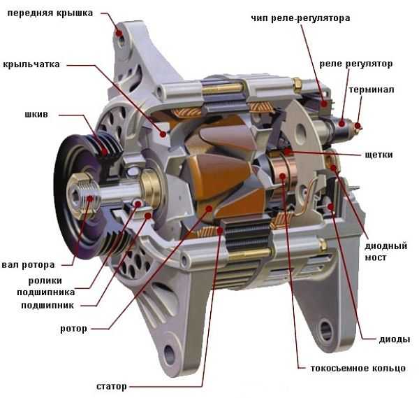
Sectional Generator
So, the main elements of the generator are:
- rotor - moving component
- the stator is stationary.
The rotor is a shaft on which the excitation winding is located, two pole halves forming a pole system and slip rings. The main task of the excitation winding is to create a magnetic field. But to achieve this effect, it needs a small amount of electric current. While the engine is not running, the current to excite the field is taken from the battery. After starting and reaching a certain speed, the current generated by the generator begins to flow to the winding, that is, the device goes into self-excitation mode.
The excitation winding is placed between two pole halves. These halves were made by stamping, which made it possible to form 6 beak-shaped protrusions on them, which are placed on top of the winding.
Slip rings are needed to supply electric current to the winding. The excitation winding leads are suitable for these rings.
Additionally, a drive pulley, a cooling fan and rolling bearings are located on the rotor.
The stator is designed to receive alternating current, which is formed due to the influence of the magnetic field of the rotor. It consists of two parts - a core and windings. The core is a package assembled from sheet steel. Grooves are made in it, in which the windings are placed - three pieces (three phases). Their laying is carried out by a loop or wave method. At the same time, they are interconnected according to one of such schemes - a “star” or a “triangle”.
The "star" scheme boils down to the fact that one end of each of the windings is connected at one point, and the other ends are the conclusions. In the "triangle", the connection of the windings is made in a ring - the first winding is connected to the second, the second - to the third, the third - to the first. The connection points of the windings are the conclusions.
The rotor is placed inside the stator, which in turn is clamped between two housing covers. These lids also contain seats under the rotor bearings. The front cover (the one on the side of the pulley) has ventilation holes.
The back cover contains the remaining necessary elements:
- brush block;
- diode bridge, also known as a rectifier unit;
- voltage regulator.
The brush block is designed to transmit electric current to the excitation winding. For this this block includes in its design two spring-loaded graphite brushes placed in the housing. Springs press these brushes against slip rings, but there is no rigid connection between them.
Video: Automobile generator. generator device. Very interesting!
The diode bridge provides AC to DC conversion. Its design includes six diodes installed in heat sink plates. Each of the stator windings has two diodes - "plus" and "minus".
A voltage regulator is an element that ensures that the output voltage is maintained within a strictly specified range. The fact is that the amount and parameters of the generated energy depend on the speed of the motor. The battery is very "sensitive" to the voltage applied to it. If it is insufficient, then the battery will be undercharged, and if it is in excess, it will be overcharged. Both lead to a significant reduction in battery life. On modern cars semiconductor electronic controllers are used, which are often made integral with the brush block.
How does a car generator work?
Now about how everything works. When the ignition is turned on, voltage is applied to the excitation winding through the brush block and slip rings, due to which a magnetic field appears around it. Since the rotor, after starting the motor, constantly rotates, and the magnetic field of its winding along with it. This field acts on the stator windings, due to which an electrical alternating current appears on their terminals, which is supplied to the rectifier unit. At the output of it, there is already a direct current, which is supplied to the voltage regulator. Part of it is fed to the brushes to ensure the self-excitation mode, while the rest goes to recharging the battery and powering consumers.
Adjusting the output voltage with a regulator is quite simple. Since it is connected to the brush block, it simply changes the voltage applied to the excitation winding, which in turn affects the magnetic field and the amount of energy generated. Another feature of the controller is thermal compensation. It boils down to the fact that the voltage supplied to the battery varies with temperature. At low temperatures, the voltage is increased, but as it increases temperature indicator the voltage will decrease.
Video: Quick check of the GENERATOR without installing it on a car
Main generator malfunctions
The generator has quite robust design, but it also has faults. They can be divided into mechanical and electrical.
- Mechanical failures are usually caused by wear on bearings, brushes, drive belt and pulley. Usually, these breakdowns are not difficult to identify, since they are all accompanied by the appearance of third-party noises or squeaks from the generator. These malfunctions are usually eliminated by replacing the worn element.
- There are more electrical faults - breakage or short circuit of the windings of the rotor or stator, breakdown of diodes, failure of the regulator. These malfunctions are both more difficult to identify and eliminate. Wherein electrical faults before detection can adversely affect the battery. For example, a faulty regulator ensures that the battery is constantly recharged. In this case, there will be no special signs, and a malfunction can only be detected by measuring the output voltage from the generator. But before the failure of the regulator is detected, it can already cause irreparable harm to the battery.
All electrical faults, in addition to open and short circuits, are usually eliminated by replacing the defective element. As for the problems with the windings, they are corrected by rewinding.
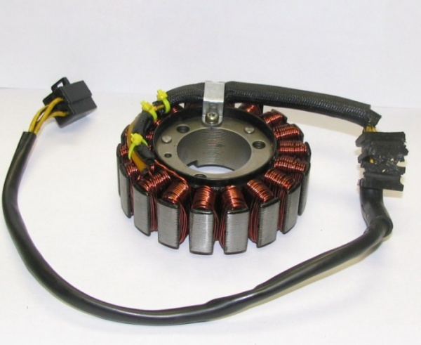
The main node in the electrical network of the car is considered to be a generator. Thanks to the operation of this device, all consumers of the car's energy are supplied with current, from optics and radio to auxiliary devices, such as a navigator and a registrar. One of the main elements this mechanism is the generator stator. You can learn more about its device, diagnostics and winding rewinding in this article.
The device and principle of operation of the generator stator
The stator element consists of the following parts:
- the windings themselves;
- core or package;
- leads for connection to a rectifier.
Structurally, the stator device consists of three windings, in which three different meanings alternating current, such a circuit is a three-phase output. One end of each winding is connected to the body of the generator unit, and the other end is connected to the rectifier. In order to strengthen and concentrate the magnetic field in the winding elements, the wires from each winding are laid around the core, which, in turn, must be made in the form of metal plastics.
The winding of the stator device is located in special grooves, the number of which in most units is 36. In the groove itself, the winding is fixed with a groove wedge, which is also made of insulating material.
Possible malfunctions: signs and causes
In the operation of the stator mechanism, two types of breakdowns can occur - this is a break in the windings or their short circuit to ground. As a result of prolonged exposure to humidity and temperature changes on the end surface of the core, the insulation can delaminate and crack. This, in turn, can cause a short circuit and an accelerated failure of the unit as a whole. Regardless of the cause, there is only one symptom of a malfunction - the generator unit ceases to function normally, malfunctions appear in its operation, and the unit cannot generate current.
Checking the generator stator with a multimeter
How to check the mechanism for damage? Depending on the fault, the stator mechanism can be checked for an open or short circuit.
To diagnose a break, you will need a multimeter or a test light:
- Take the tester and activate it in ohmmeter mode, then connect the probes to the winding terminals. In the event that there is no open circuit in the device, the tester should display a resistance value of about 10 ohms. If there is a break in the device, respectively, the current cannot pass to the windings, then the resistance value will tend to infinity. IN this case All three outputs need to be checked.
- As for the control diagnostics, in this case you will need to apply a negative charge from the battery to one of the contacts of the winding device. To do this, you need an insulated wire. A positive charge will need to be applied through the control to another contact. If the light source began to burn, this indicates that the device is working normally, if not, then there is a break in the system. The verification procedure will need to be repeated for each output.
![]()
With regard to diagnostics for short circuit, then it can also be carried out using a tester or a lamp:
- The negative tester probe should be connected to the stator, and the multimeter should be set to ohmmeter mode. The positive probe is connected to the winding contact, no matter which one. The procedure is repeated for each output.
- As for the diagnostic control, it is carried out in a similar way. The negative terminal of the battery is connected to the terminal of the stator mechanism, and the positive terminal is connected from the battery to any terminal. If the light began to burn, this indicates that there is a short circuit in the mechanism, if not, then the device is working in normal mode. Diagnostics is carried out with each output (the author of the video is the altevaa TV channel).
Do-it-yourself generator rewind instructions
Repair of the stator consists in rewinding the windings.
How to do this procedure yourself:
- First of all, you need to disassemble the generator unit and remove the stator from it.
- The existing windings must be burned so that they burn out, but before that you should count the number of turns and make an appropriate circuit for rewinding. In this case, on the stator it will be necessary to mark the places of the conclusions for the beginning and end of the winding. Do not be afraid to burn it, it will not spoil the iron, its magnetic characteristics will not be violated.
- After combustion, cleaning is carried out.
- Further, using materials such as synthoflex or pressboard, it is necessary to cut insulating gaskets. Please note that they should protrude from the ends of the groove by about 2.5-3 mm. When one of the spacers is made and fitted to the dimensions, it will be necessary to cut a piece of tape in accordance with its width or length. Then, using this spacer, cut 36 pieces of the same length and fit them into the slots.
- Then the rewind takes place. The essence of rewinding is that the postings from one groove go, as it were, in a wave immediately to the fourth. Having wound half of the turns in one phase, winding is performed in reverse side, while you need to cover the empty parts of the half-coils. All phases are wound in the same way.
- When the phases are rewound, you will need to seal the grooves by installing the protruding parts of the gaskets in them. It is necessary to ensure that the protruding parts of the semi-coils do not protrude beyond the boundaries of the metal inside, as well as beyond the boundaries of the fastening from the outside. To do this, through the spacers of the coil should be tapped.
- At this stage, you can check and try on the stator in the cover of the generator unit, make sure that the windings do not touch the housing. If there is a touch, then you need to get rid of it.
- Clean and connect the leads of the winding elements, to do this, twist them together and solder them. They will also need to be insulated, for this you can use textile cambric.
- Before direct connection, you need to make sure that there is no short circuit between the phases, as well as to the metal. If there is a short circuit, then it is necessary to find the place of contact, and then insulate it, this will require another gasket.
- After completing these steps, you will need to tie the winding element and fix its contacts with a cord. If it is not there, you can use linen thread, but not nylon thread, otherwise it will melt and flow when dried. The stator mechanism needs to be slightly warmed up, this is done to dry, and then placed in a container with impregnating varnish or a similar substance. Furniture varnish must not be used.
- When the device is saturated, hang it up and wait for a while until all the varnish has drained. Then the device is recommended to be placed in the oven conventional stove, which needs to be set to minimum heating, it would be better to hang it, and install an old tile under it. Or something like that, the main thing is that the varnish does not flow onto the hot pan. Wait about one hour - if during this time the varnish stops sticking, then at the same temperature you will need to dry the device for about 2 more hours.
Photo gallery "Self-rewinding the stator"

1. Fire and remove old insulation.
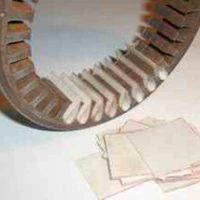
2. Prepare the stator and install the gaskets.
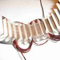
3. Start rewinding, the wire is laid in a “wave” from one groove to the fourth.

4. Wind all three phases.
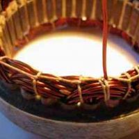
5. Fasten the leads with a cord.

6. Open the stator with varnish, dry and install in the generator.
Conclusion
As you can see, the procedure for rewinding the windings as a whole is a rather complicated and painstaking procedure; not everyone can cope with such a task. In total, its implementation will take at least four hours of free time. Moreover, if you make mistakes and find out about it only at the end, then we can assume that the time was wasted. Therefore, if you are not assiduous, then it may make sense to purchase a new stator.
Although the car runs on gasoline, it contains many devices powered by electricity. The main source of electrical energy in the car is a car generator. In fact, this is an internal power plant that converts the rotation of the engine internal combustion into electricity. This electricity feeds all the electrical appliances of the car, including due to this it is recharged accumulator battery, which is also a source of electricity when idle engine.
shown in the following figure.
G - generator;
Ph1…Ph3 – three-phase stator windings;
VD+ - power rectifier, positive diodes;
VD1- - power rectifier, negative diodes;
C is a capacitor that equalizes high-frequency voltage surges;
B+ – positive power output of the generator set;
VD1d+ - excitation winding elements;
Ex - excitation winding;
VR - volt-voltage regulator;
Accu - rechargeable battery;
+ - positive output of the storage battery;
IgnSw - ignition switch;
H - charge indicator;
D+ – output "D+" of the generating set;
DF – excitation winding control output;
R - consuming devices.
Wiring diagram car generator and the principle of its operation is similar for any car. The differences are related only to the quality of production, power and layout of components in the motor. All modern machines are equipped with alternating current generator sets, including itself and a voltage regulator. The regulator normalizes the current strength in the field winding, due to this, the power of the generator set varies with a constant voltage at the power output terminals.
Modern cars are additionally equipped with electronic unit on the voltage regulator, with which on-board computer controls the amount of load on the generator set.
The basis of the automobile generator circuit is the principle of electromagnetic induction. If a coil of copper wire is rotated in a magnetic field created by permanent magnets or an excitation winding powered by a battery, then an electric current is formed (induced) in the copper wire. As a rule, the winding in which is generated operating voltage electric current is located in the stator. The excitation winding is located on the rotor (rotating shaft).
On hybrid cars the generator acts as a starter-generator and is used in some other stop-start systems.
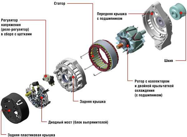
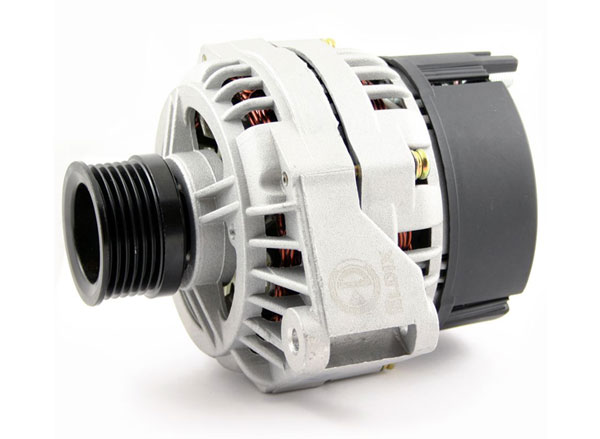
By structural design automotive generators are compact and traditional. They differ mainly only in the layout of the fan, housing design, rectifier elements and drive pulley. Almost any generator consists of: a rotor, a stator, a housing, a voltage regulator unit and a rectifier and brush assembly.
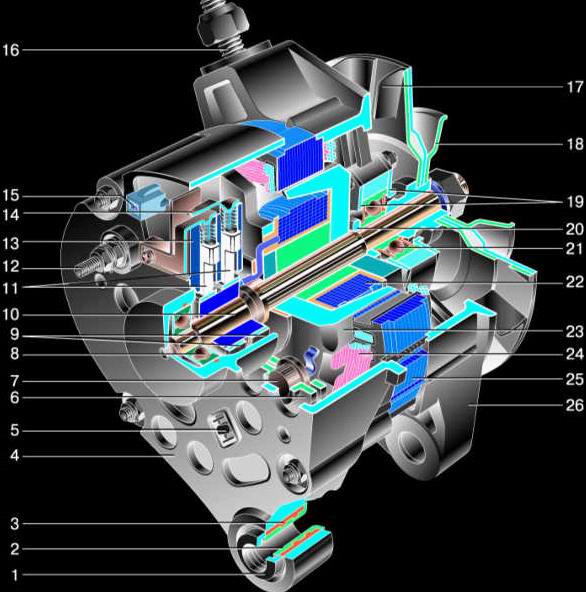
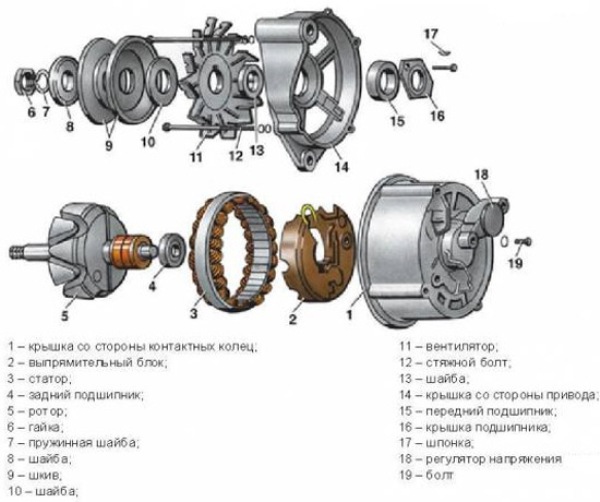
1 - clamping bushing, 2 - bushing, 3 - buffer bushing, 4 - back cover, 5 - rectifier unit fixing screw, 6 - rectifier unit, 7 - valve (rectifier diode), 8 - rear bearing, 9 - slip rings, 10 - rotor shaft, 11 - brushes, 12 - output "30" 13 - brush holder, 14 - output "67", 15 - neutral wire plug, 16 - generator mounting stud, 17 - fan impeller, 18 - pulley, 19 - plates, 20 - ring, 21 - front bearing, 22 - rotor winding, 23 - rotor, 24 - stator winding, 25 - stator, 26 - front cover
For VAZ 2110:
1 - casing, 2 - terminal "B +" for connecting consumers? 3 - interference suppression capacitance 2.2 μF, 4 - general conclusion additional rectifiers (connected to the “D +” terminal of the voltage regulator block), 5 - holder of positive rectifier diodes, 6 - holder of negative diodes, 7 - stator winding leads, 8 - voltage regulator unit, 9 - brush holder, 10 - back cover, 11 - front cover, 12 - stator core, 13 - stator winding, 14 - distance ring, 15 - washer, 16 - conical washer, 17 - pulley, 18 - nut, 19 - rotor shaft, 20 - rotor shaft front bearing, 21 - beak-shaped rotor pole pieces, 22 - rotor winding, 23 - bushing, 24 - clamping screw, 25 - rear rotor bearing, 26 - bearing bushing, 27 - slip rings, 28 - negative diode, 29 - positive diode, 30 - additional diode, 31 - output "D" (common output of additional diodes)
1 - battery; 2.3 - negative and additional diode; 4 - generator; 5 - positive diode; 6- stator winding; 7 - voltage regulator; 8 - rotor winding; 9 - capacity for suppression of radio interference; 10 - mounting block; eleven - control lamp battery charge indicator; 12 - voltage meter voltmeter; 13.14 - relay and ignition switch;
For dashboard vaz 2107
1 - battery; 2 - negative diode; 3 - additional diode; 4 - generator; 5 - positive diode; 6 - stator winding; 7 - voltage regulator; 8 - rotor winding; 9 - radio interference suppression capacity; 10 - mounting block; 11 - control lamp of the battery charge in the instrument cluster; 12 - voltmeter; 13 - ignition relay; 14 - ignition switch.
Connection diagram of the G-222 generator system |
For car VAZ 2105
1 - generator; 2 and 3 - negative and positive diode; 4 - stator winding; 5 - voltage regulator; 6 - rotor winding; 7 - capacity for suppression of radio interference; 8 – accumulator battery; 9 – the relay of a control lamp of a charge of the accumulator battery; 10 - mounting block; 11 – a control lamp of a charge of joint stock bank in a combination of devices; 12 - voltmeter; 13 - ignition relay; 14 - ignition switch
For car VAZ 2107
1 - generator;
2 - negative diode;
3 - positive diode;
4 - stator winding;
5 - voltage regulator;
6 - rotor winding;
7 - capacitor for suppression of radio interference;
8 - battery;
9 - relay of the control lamp of the battery charge;
10 - mounting block;
11 - control lamp of the battery charge in the instrument cluster;
12 - voltmeter;
13 - ignition relay;
14 - ignition switch
Generator Basics |
Rotor - creates a rotating magnetic field, for this purpose there is an excitation winding on the shaft. It is located in two halves of the pole, each of which has six protrusions - they are called beaks. There are also two contact rings on the shaft and it is through them that the excitation winding is powered. Rings are usually copper, but sometimes steel and brass are found. The excitation winding leads are connected to the rings.
On the rotor shaft there is one or two fan impellers and a driven driven pulley is fixed. Two unattended ball bearing form the bearing assembly of the rotor. On the side of the slip rings on the shaft, a roller bearing is very often located.
The stator is used to generate alternating current, consists of a metal core and a winding, the core is assembled from steel plates and has thirty-six grooves for winding windings, three windings are located in the grooves, forming a three-phase connection. There are two methods for laying windings in the stator slots - the wave method and the loop method. The windings are connected to each other according to the "star" and "triangle" scheme.
The vast majority of the structural components of the generator are located in the housing. The case consists of two aluminum covers - front and back. The front one is on the side of the drive pulley, the rear one is on the side of the slip rings. The covers are bolted together. On the surface of the covers there are ventilation holes, and mounting tabs. Depending on the number of paws, a single-blade or two-blade generator mount is distinguished.
The brush assembly is designed to ensure the transfer of exciting current to the slip rings. The unit consists of 2 graphite brushes and clamping springs, as well as a brush holder. Usually the brush holder is located with the voltage regulator in one module.
The rectifier unit is designed to convert the sinusoidal voltage generated by the generator into constant pressure for the car's onboard network. The module contains - 6 power semiconductor diodes, i.e. for each phase - two rectifiers, one for the "positive" and the other for the "negative" output.
On most modern generators, the field winding is connected through a separate contact group consisting of two diodes. These diodes prevent the battery discharge current from flowing through the winding when the engine is not running. If the windings are connected by a “star”, two additional power diodes are located on the zero terminal, providing an increase in the generator power by up to 15%. The rectifier unit is connected to the circuit using special pads by soldering, welding, or screw connection.
Voltage regulator - necessary to maintain the voltage from the generator output in the specified parameters. voltage regulators. It comes in hybrid and integral versions.
Voltage stabilization is carried out when the engine crankshaft speed changes. The voltage regulator controls the repetition rate and duration of the pulses. In addition, it implements a voltage change to charge the battery during temperature compensation depending on the temperature. environment. The higher the temperature, the lower the voltage value supplied to the battery.
With the help of a belt drive, the rotor rotates at a speed two to three times the speed. crankshaft. Depending on the design of the generator, a V-ribbed or V-belt is used.
There is also an inductor generator, that is, brushless. It consists of a rotor consisting of a set of compacted thin transformer iron plates. The stator has an excitation winding. By changing the magnetic conductivity of the air gap between the rotor and stator.
If in car lock turn the ignition key, current flows to the excitation winding through the brush assembly and slip rings. In the winding is created. The generator rotor begins to move along with the rotation of the crankshaft. Stator windings are threaded magnetic field rotor. An alternating voltage appears on the terminals of the stator windings. With the achievement of a given speed, the excitation winding is powered by the generator, that is, the generator is in self-excitation mode.
AC voltage is rectified to DC. In this state, the generator generates the required current to charge the consumers and the battery. The voltage regulator is connected to work when the load and shaft speed change. The turn-on time of the field winding decreases with a decrease in load and an increase in the generator speed. The time increases with increasing load and decreasing speed. When the confirmation current exceeds the capabilities of the generator, the battery starts to work. On the forward panel of devices there is a control lamp displaying a condition of the generator.
After running the first 2000 km and every subsequent 15000-20000 km, it is necessary to check the condition and tension v-belt generator drive. To do this, press hard with your thumb on the belt approximately in the middle. At the same time, it should not bend more than 5 mm, and if new, then no more than 2 mm. If the deflection distance is less than the V-belt, it must be tightened or replaced.
To remove the belt, in some car models, it is necessary to loosen the fixing screws, and then use a pry bar or a powerful screwdriver to move the generator to the engine and remove the belt. In car models with tension roller the roller is pressed and with the help of the cap head loosen the tension and remove the belt.
To increase the belt tension, it is necessary to loosen the fixing screws, use a screwdriver to slightly turn the generator away from the engine and fasten the screw again. In models with a tension roller, the latter independently adjusts the belt tension.
When checking the V-belt or V-ribbed belt, make sure that the latter is not frayed and that there are no cracks or breaks on it. If they are, the belt must be replaced with a new one. If the engine is equipped with a double V-belt, this pair must be replaced together.
Generator malfunctions. If there is a sufficiently loud, metallic noise, it is necessary to check if the pulley nuts are loose. If the cause is not in them, the bearings may be damaged or an inter-screw short circuit to ground could occur.
When connecting the battery, check that the connection to the terminal pins is correct. In addition, the battery must not be disconnected from the on-board network when the engine is on and consumers are disconnected. Therefore, during any maintenance of the generator, it is necessary to check the health of the battery charging circuit.
It is impossible to allow the wires to come into contact with the voltage regulator housing. It is best to place them at a distance of 3-5 cm. Because the regulator can get very hot during operation, and the insulation of the wires can be broken. The cover of the regulator must always be pressed very tightly against the body, and the gasket between the cover and the body must perfectly insulate the space under the cover.
Generator brush replacement. Alternator brushes must be checked after 50,000-60,000 km of run. This does not require dismantling the generator, but only:
Disconnect the negative cable from the battery, then unscrew the voltage regulator. If the worn brushes protrude from the brush holder by less than 5 mm, they must be replaced with new ones. Before installing the regulator with a new brush holder, it is necessary to clean the brush holder seat from accumulated carbon dust. Solder to replace brushes connecting wires, and if necessary, clean the contact surface and check the force of contact of the contact springs.
After installing new brushes, check that they move freely in the holder. Then lightly attach the voltage regulator with the locking screw, and with pressure, but very carefully, set it to its final position and tighten it tightly. Do not forget to connect the ground cable to the battery after the alternator brush replacement process is completed.
Sometimes, on a new car, the warning light on the dash may erroneously indicate "no battery". This is because the brushes have not yet had time to get used to the new generator.
An electrical machine that converts mechanical energy into electrical current is called a car generator. The function of the generator, which it performs in the car, is to charge the battery and power electrical equipment with the engine running. An alternator is used as a car generator.
The generator is located in the engine, most often in its front part, driven from the crankshaft. On hybrid vehicles, the generator performs the work of a starter-generator, a similar scheme is used in some other designs of the stop-start system. Denso, Delphe and Bosch are currently the world's leading manufacturers of alternators.
There are two types of car generator designs: compact and traditional. The differences that characterize these types consist of a difference in the layout of the fan, they differ in the design of the housing, the rectifier unit and the drive pulley, geometric dimensions. The general parameters available in both types of automotive generators are:
- Rotor;
- stator;
- Frame;
- Voltage regulator;
- Rectifier block;
- Brush knot.
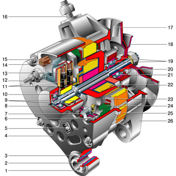
| 1 - clamping sleeve | 14 - output "67" |
| 2 - bushing | 15 - neutral wire plug |
| 3 - buffer sleeve | 16 – a hairpin of fastening of the generator |
| 4 - back cover | 17 - fan impeller |
| 5 - screw for fastening the rectifier unit | 18 - pulley |
| 6 - rectifier block | 19 - plates |
| 7 - valve (diode) | 20 - ring |
| 8 - rear bearing | 21 - front bearing |
| 9 - contact rings | 22 - rotor winding |
| 10 - rotor shaft | 23 - rotor |
| 11 - brushes | 24 - stator winding |
| 12 - output "30" | 25 - stator |
| 13 - brush holder | 26 - front cover |

| 1 - casing | 17 - pulley |
| 2 - output "B +" for connecting consumers | 18 - nut |
| 3 - noise suppression capacitor 2.2 uF | 19 - rotor shaft |
| 4 - common output of additional diodes (connected to the “D +” output of the voltage regulator) | 20 - front bearing of the rotor shaft |
| 5 - holder of positive diodes of the rectifier unit | 21 - beak-shaped pole pieces of the rotor |
| 6 - holder of negative diodes of the rectifier unit | 22 - rotor winding |
| 7 - stator winding leads | 23 - sleeve |
| 8 - voltage regulator | 24 - coupling screw |
| 9 - brush holder | 25 - rear rotor bearing |
| 10 - back cover | 26 - bearing sleeve |
| 11 - front cover | 27 - slip rings |
| 12 - stator core | 28 - negative diode |
| 13 - stator winding | 29 - positive diode |
| 14 - remote ring | 30 - additional diode |
| 15 - washer | 31 - output "D" (common output of additional diodes) |
| 16 - conical washer |

1 - generator; 2 - negative diode; 3 - additional diode; 4 - positive diode; 5 - control lamp of the battery discharge; 6 - instrument cluster; 7 - voltmeter; 8 - mounting block; 9 - additional resistors of 100 Ohm, 2 W; 10 - ignition relay; 11 - ignition switch; 12 - battery; 13 - capacitor; 14 - rotor winding; 15 - voltage regulator
The main task of the rotor- create a rotating magnetic field, for this purpose, the excitation winding is located on the rotor shaft. It is placed in two halves of the pole, each pole half has six protrusions - they are called beaks. There are also contact rings on the shaft, there are two of them, and it is through them that the excitation winding is powered. Rings, most often, are made of copper, steel rings or brass rings are quite rare. The leads of the excitation winding are soldered directly to the rings.
One or two fan impellers are placed on the rotor shaft (their number depends on the design) and a driven drive pulley is fixed. Two maintenance-free ball bearings make up the rotor bearing assembly. A roller bearing can also be located on the side of the slip rings on the shaft.
The stator is necessary to create an alternating electric current, it combines a metal core and windings, the core is made of plates, they are made of steel. It has 36 grooves for winding windings, windings are laid in these grooves, there are three of them, they form a three-phase connection. There are two ways to lay the windings in the grooves - the wave method and the loop method. The windings are connected to each other according to the "star" and "triangle" schemes.
What are these schemes?
- "Star" - one ends of the windings are connected at one point, and the other ends are conclusions;
- "Triangle" - an annular connection of the ends of the windings in a sequence, the conclusions come from the connection points.
The brush assembly serves to ensure the transfer of excitation current to the contact rings. It consists of two graphite brushes, springs that press them, and a brush holder. In generators modern machines the brush holder is located with the voltage regulator in a single non-separable unit.
The rectifier unit performs the function of converting the sinusoidal voltage generated by the generator into a voltage direct current vehicle onboard network. These are plates that act as heat sinks, with mounted diodes. There are six power semiconductor diodes in the block, two diodes for each phase, one for the “positive” and the other for the “negative” output of the generator.
On many generators, the excitation winding is connected through a separate group, which consists of two diodes. These rectifiers prevent the battery discharge current from flowing through the coil when the engine is not running. When the windings are connected according to the "star" principle, two additional power diodes are installed on the zero terminal, allowing you to increase the generator power by up to 15 percent. The rectifier unit is connected to the generator circuit at special mounting sites by soldering, welding, or bolting.
Voltage regulator- its purpose is to maintain the generator voltage within certain limits. Currently, generators are equipped with semiconductor electronic (or integral) voltage regulators.
Voltage regulator designs:
- hybrid design - the use of radio elements and electronic appliances V electronic circuit together;
- integrated design - all components of the regulator (not counting the output stage) are made using thin-film microelectronic technology.
The voltage regulator produces a change in the voltage supplied to charge the battery by temperature compensation of the voltage (depending on t air). The higher the air temperature, the less voltage goes to the battery.
The generator is driven by a belt drive, it ensures the rotation of the rotor at a speed exceeding the crankshaft speed by two to three times. In different designs of the generator, a poly-V-belt or a V-belt can be used:
- V-belt has the prerequisites for rapid wear (depending on the specific pulley diameter) since the scope of the V-belt is limited by the size of the driven pulley.
- V-ribbed belt is considered more universal, applicable for small diameters of the driven pulley, with its help more gear ratio. Modern models generators have a multi-ribbed belt in their designs.
When the key is turned in the ignition lock, current is supplied to the excitation winding through the brush assembly and slip rings. A magnetic field is induced in the winding. The generator rotor begins to move with the rotation of the crankshaft. The stator windings are pierced by the magnetic field of the rotor. An alternating voltage appears on the terminals of the stator windings. When a certain speed is reached, the excitation winding is powered directly from the generator, that is, the generator goes into self-excitation mode.
The alternating voltage is converted by the rectifier unit into a constant one. In this state, the generator is engaged in providing the required current to charge the power supply to consumers and the battery.
The voltage regulator is activated when the load and crankshaft speed change. He is engaged in adjusting the turn-on time of the excitation winding. The turn-on time of the field winding decreases with a decrease in the external load and an increase in the generator speed. Time increases with increasing load and decreasing speed. When the current consumed exceeds the capabilities of the generator, the battery is switched on. On the instrument panel there is a control lamp that controls the operable state of the generator.
The main parameters of the generator:
- Rated voltage;
- rated excitation frequency;
- rated current;
- frequency of self-excitation;
- Efficiency (coefficient of performance).
Current-speed characteristic- this is the dependence of the current strength on the frequency of rotation of the generator.
In addition to the nominal values, the current-speed characteristic has other points:
- minimum current and minimum operating speed (40-50% of the rated current is the minimum current);
- maximum current and maximum speed (no more than 10% maximum current exceeds the rated current).
Video


