LECTURE 10
Rolling bearings
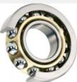
The rolling bearing is a finished unit, the main element of which is the rolling elements - balls or rollers installed between the rings and held at a certain distance from each other by a cage called a cage (Fig. 21.6) 1 - outer ring; 2 - inner ring; 3 - ball; 4 - separator.
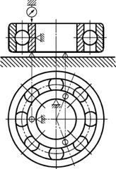
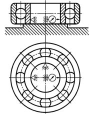
During operation, the rolling elements roll along the raceways of the rings, one of which is stationary in most cases. The load distribution between the bearing rolling elements is uneven (Fig. 21.7) and depends on the size of the radial clearance in the bearing and on the accuracy of the geometric shape of its parts.
Rice. 21.6. Rice. 21.7. Rice. 21.8.
In some cases, to reduce the radial dimensions of the bearing, there are no rings (Fig. 21.8, a block of gears on bearings with needle rollers) and the rolling elements roll directly along the trunnion and housing.
Rolling bearings are widely used in all branches of engineering. They are standardized and manufactured in mass production at a number of large specialized factories.
Advantages and disadvantages of rolling bearings
Advantages: 1. Relatively low cost due to mass production of bearings.
2. Low friction loss and low heating. Friction losses during start-up and steady state operation are almost the same.
3. High degree interchangeability, which facilitates the installation and repair of machines.
4. Low lubricant consumption.
5. Do not require special attention and care.
Disadvantages: 1. High sensitivity to shock and vibration loads due to the high rigidity of the bearing structure.
2. Unreliable in high speed drives due to excessive heating and the danger of destruction of the separator from the action centrifugal forces.
3. Relatively large radial dimensions.
4. Noise at high speeds.
Classification of rolling bearings and their marking
Rolling bearings are classified according to the following main features:
According to the shape of the rolling elements (Fig. 21.9) - ball ( A) and roller, and the latter can be cylindrical ( b), conical ( V), barrel-shaped ( G), needle-like ( d) and twisted ( e) rollers;
In the direction of the perceived load - radial, radial-thrust, thrust-radial and thrust;
According to the number of rows of rolling elements - single-row and multi-row;
According to the ability to self-align - non-self-aligning and self-aligning (spherical);
By overall dimensions- on the series.
For each type of bearing with the same inner diameter, there are different series that differ in the size of the rings and rolling elements. Depending on the size of the outer diameter of the bearing, the series are: ultralight, extra light, light, medium and heavy.
Rice. 21.9. Rolling elements of bearings
Depending on the width of the bearing, the series are divided into extra narrow, narrow, normal, wide and extra wide.
Rolling bearings are marked by applying a series of numbers and letters to the end of the rings, conditionally designating the inner diameter, series, type, design varieties, accuracy class, etc.
Main types of rolling bearings
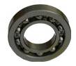
Deep groove ball bearing (Fig. 21.10, A) is the most common bearing in mechanical engineering. It is cheap, allows misalignment of the inner ring relative to the outer ring up to 0 ° 10". Designed for radial load. Having grooved raceways, it can also take axial load. Provides axial fixation of the shaft in two directions. With the same overall dimensions, it works with lower friction losses and with more angular velocity shaft than bearings of all other designs.
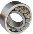
Ball radial spherical bearing (Fig. 21.10, b) is designed for radial loading. Simultaneously with the radial one, it can take a small axial load and work with a significant (up to 2-3 °) misalignment of the inner ring relative to the outer one. The ability to self-adjust determines the scope of its application.
Roller radial bearing with spherical rollers (Fig. 21.10, V) has the same characteristics as a spherical ball, but has the highest load capacity of all other bearings of the same overall dimensions.
Roller radial bearing with short cylindrical rollers (Fig. 21.10, G) takes only radial load. Allows axial mutual displacement of the rings. It is used for short rigid shafts, as well as "floating" supports (for herringbone gear shafts, etc.). Its load capacity is on average 1.7 of the load capacity of a ball radial.
Roller radial bearing with needle rollers (Fig. 21.10, d) takes only radial load. With relatively small overall dimensions, it has a high radial load capacity.
Ball radial thrust bearing(Fig. 21.10, e) is designed for combined (radial and axial) or purely axial loads. Bearings mounted in pairs absorb axial forces acting in both directions. Used for rigid shafts at high speeds.
Tapered roller bearing (Fig. 21.10, and, h) perceives both radial and axial loads. Used for medium and low speeds rotation. Possesses heavy load capacity. Conveniently adjustable. It does not allow distortion of the rings, therefore, it requires rigid shafts, precise boring of housings and careful installation. Bearings of this type, like the previous ones, are installed in pairs, they must be loaded with an axial force - external or specially created during assembly.


Rice. 21.10. Types of rolling bearings

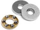
Rice. 21.11. Ball thrust bearing
Ball thrust bearing (Fig. 21.10, A) perceives a one-sided axial load. Under the action of axial forces, a double thrust bearing is installed alternately in both directions (Fig. 21.10, b). To avoid jamming of the balls due to centrifugal forces, this bearing is used at medium and low speeds.
Rolling bearings usually consist of (Fig. 35): of two rings outdoor 1 And internal 2, rolling elements 3(balls or rollers) and separator 4(from lat. separator- separator), separating the rolling bodies from each other.
The inner ring is mounted on the shaft or axle, the outer one is installed in the body of the machine support unit. In the most common designs, the inner ring is movable, and the outer ring is fixed.
Standard bearings are divided into the following types according to their main features. By the shape of the rolling elements- on ball (Fig. 36 a, b, c, f) and roller (Fig. 36 d, e, g, h); according to perceived loads- on radial (Fig. 36 a, b, d, g, h,), radial-thrust (Fig. 36 c, e), stubborn (Fig. 36 f) and stubbornly radial; according to the most important design feature– on self-aligning (spherical) (Fig. 36 b) and non-self-aligning (the rest); according to the number of rows of rolling elements- for single row (Fig. 36 a. c, d, e. f, g, h), double row (Fig. 36 b) and four rows.
Bearings of the same bore diameter are subdivided according to overall dimensions (outer diameter and width) into series: super light, extra light, light, light wide, medium, medium wide and heavy (Fig. 37)
 Radial ball bearings designed to absorb mainly radial loads. However, in addition to the radial load, they can transmit an axial load up to 70% of the unused radial load. When using these bearings, lower requirements are placed on the alignment of the bearings and the rigidity of the shafts. They are cheaper than other types of bearings, allow easier mounting and dismounting. Therefore, they are most often used in various machines and mechanisms.
Roller bearings possess higher load capacity than ball ones. However, roller bearings with cylindrical rollers of the most common designs cannot perceive axial loads, and tapered roller bearings are less fast.
Angular contact bearings distinguished by the angle of contact α (Fig. 36 b). With increasing contact angle angular contact bearings can take heavier axial loads, but the speed of the bearings is reduced.
self-aligning bearings (Fig. 36 b) used in case of increased misalignment of the shaft supports (up to 2º ... 3º), as well as with increased shaft compliance.
The material of balls and rollers with a diameter of up to 20 mm, as well as bearing rings with a wall thickness of up to 12 mm, is usually high-carbon chromium steel grade ShKh15. Yield strength in tensile testing of hardened specimens of this steel σ Т = 2200…2600 MPa. For the manufacture of rollers and rings of larger sizes, steels with increased level doping - SHKH15SG And SHH20SG, because more high content in them, silicon and manganese reduces the cooling rate of the metal and allows you to harden parts to a greater depth. Bearing rings can also be made of other steels (for example, those intended for surface hardening).
Cages for mass bearings are stamped from mild carbon steel; separators of high-speed bearings are made of bronze, brass, duralumin, textolite and other materials. If bearings must have special properties (anti-corrosion, non-magnetic, etc.), then their parts are made from appropriate materials.
The bearing has been used as an assembly unit of any mechanism for quite a long time. It is difficult to imagine a car or unit without it. It serves to support or stop the shaft, to maintain a given rigidity with minimal resistance to friction.
Two types of bearings are especially common: rolling and sliding.
The most widely used type. It consists of the following parts:
- inner ring.
- Separator (clip).
- Rolling bodies.
- outer ring.
- Protective cover (not always used).
Such bearings are used in equipment of all industries and purposes. Moreover, this type is very diverse. Rolling bodies are: spherical, roller, barrel-shaped, needle-shaped. Steel is predominantly used as the body material. In particularly aggressive environments, glass rolling bodies are used. 
On the inner ring on the outside is machined groove. They also make a gutter inside outer ring. These grooves are the paths for the rolling elements. Thus, the balls rotate pointwise touching the bottom of the groove and its walls. Roller bodies during rotation touch the entire plane of the grooves.
The separator, as a rule, consists of two halves soldered together. Its role is to create a direction for the movement of bodies and maintain a constant equal distance between them. In some cases, a rolling bearing without a cage is used, which makes it possible to increase the load on the assembly, however, the rotation speed cannot be high with this design. 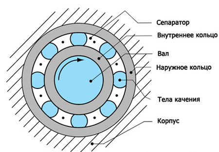
According to the perceived load, the rolling bearing is classified into thrust, radial, radial-thrust. On radial load is distributed perpendicular to the axis of the shaft. The load along the shaft is not allowed.
Thrust take the load parallel to the axis. The transverse shaft load is prohibited.
Radially resistant. They can take the load both parallel and perpendicular to the axis of the shaft.
In order to reduce the dimensions, in some cases the inner ring is not used. With this type of operation, a groove is machined on the shaft, stationary or active, and the separator with the outer ring is put directly on the axis or shaft of the mechanism.
Depending on the number of rows of rolling elements, the bearing can be single-row, double-row and multi-row. Double-row and multi-row are mainly used as thrust or radial-thrust and are able to withstand significantly higher loads than single-row.
Bearings with protective cover more durable and require less maintenance. Open ones can quickly fail with insufficient or improper lubrication and foreign objects.
Used for rolling bearings different kinds lubricants: liquid ( various oils), plastic (solid oil), solid ( graphite grease). Sometimes bearings run without lubrication, however, the speed of rotation of the rolling elements should not be high, and the load should be large. Otherwise, the bearing heats up quickly and fails.
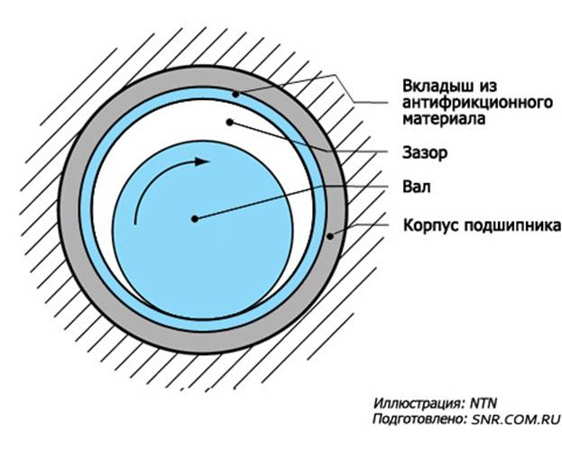
IN this type bearing, friction occurs when the mating planes of the shaft and bushing slide.
The plain bearing consists of the following elements:
- Housing (solid or collapsible).
- Insert or sleeve (made of anti-friction material).
- Lubricating device.
The case for this type is most often massive, made of different metals and can be one-piece or split. The body is equipped with one or more oil valves. The valve serves to supply lubricant to the working plane of the liner or bushing. Also, when lubricating under pressure, with the help of special oil stations, there is a drain for used oil, which then enters the station and again on the bearing. Thus, the lubricant is circulating. 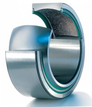
The liner is often made of anti-friction metals, such as: bronze and cast iron. Babbitt-coated steel liners can be used.
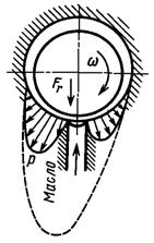
The principle of operation is quite simple. An insert or sleeve is mounted in the body. Then the structure is attached to the shaft trunnion. There should be a small gap between the trunnion and the bushing for lubrication. During the movement of the shaft, the lubricant separates the axle from the bushing, thereby reducing the friction force. However, during start-up, the shaft touches the bearing walls for some time, and this requires a layer of anti-friction metal.
Plain bearing is classified into radial, thrust, radial thrust.
As lubricant oils are predominantly used. Plastic, solid and even gaseous lubricants are also used.
The difference between plain and rolling bearings
The plain bearing has a number of advantages that distinguish it from the rolling bearing:
- It has a detachable version. This is a huge plus for engine use. internal combustion. On crankshaft it is not possible to put on a rolling bearing. That is why a plain bearing is used.
- An economical option for use on large diameter shafts.
- Able to work in water.
- When repairing, there is no need to dismantle the remaining parts.
- Unlike ball bearings, they can take large vibration and shock loads.
- The dimensions of radial type bearings are relatively small.
- It is possible to adjust the gap between the shaft and the bushing.
- Simple in slow cars.
- Reliable in high speed drives.
- Silent operation.
However, rolling bearings have their advantages:
- Materials for manufacturing are cheaper.
- Does not require constant lubrication supervision.
- No increased friction at start-up.
- Less consumption of lubricants.
- Less friction force.
- Thrust type bearings are smaller.
Each type of bearing has its own advantages and weak sides, which allows the use of separate view under certain conditions. From the general purpose, only the purpose is to support the shaft and create minimal friction during operation.
Rolling and sliding bearings
Abstract on the discipline "Physics"
Completed: student gr. VAU - 126 6 Shipaev V.V.
Volga Polytechnic Institute
Volzhsky 2013
Bearings have been used since ancient times. Depending on the operating conditions of mechanisms and machines (speed, load, temperature environment, fin. costs, ...) certain types of f / w are selected by calculation, which are made from various materials.
The purpose of the bearing is to reduce friction between the moving and stationary parts of the mechanism, because friction is associated with wear, heat and energy loss.
ROLLING BEARING: -support of the rotating (moving) part of the mechanism operating under the prevailing ROLLING FRICTION. Usually consists of an outer ring, rolling elements (ball, roller), cage, inner ring (Fig. 1). Fig. 1
The rolling elements come into contact with the outer and inner ring, which, when rotated, results in slip friction. Energy losses are associated with sliding friction of the rolling elements against the cage, internal friction in the material of the contacting bodies (elastic deformation), and lubrication resistance.
They are classified: - by rolling elements: ball, roller (cylindrical, conical, needle, twisted, barrel-shaped, barrel-shaped conical, ...).
By type of load: radial (load perpendicular to the axis of rotation);
radial-thrust (load perpendicular and along the axis of the shaft);
linear (provide movement along the axis, rotation around the axis is not standardized or not possible);
ball screws (screw-nut interface through rolling elements).
According to the number of rolling elements (single, double, and multi-row).
According to the ability to compensate for misalignment of the shaft and p / w (conventional and self-aligning).
In ball bearings POINT OF CONTACT (lower coefficient of friction). In a roller bearing LINE OF CONTACT (greater coefficient of friction).
Therefore, with the same dimensions, ball-p / w allow great speed rotation, but perceive less load than roller-p / w.
Advantages of p / w rolling:
High rotation speed;
Withstand heavy loads;
Small width (axial size);
Moderate lubrication requirements;
Large operating temperature range (special f/w up to 1000°C).
Disadvantages of p / w rolling:
High price;
Difficulty in manufacturing;
Large radial dimensions.
Applicable materials:
Basically, p / w are made of high-carbon low-alloy steel (outer and inner rings, rolling elements are hardened), low-carbon steel, brass (cage, protective washers). To operate under dynamic loading, the rings and rollers are made of low-carbon low/medium alloy steel subjected to surface carbon saturation, i.e. cementation (cementite structure): the surface layer after quenching and tempering is hard, wear-resistant, and the core is viscous, elastic (such p / w are used in rolling mills, axle boxes of railway cars, aircraft landing gear).
Recently, other materials have also been used: ceramics, fluoroplast, textolite ...
Production of rolling bearings:
Industrial production of roller bearings was first organized in Germany in 1883, in the Soviet Union in 1932 (in 1961, the 1st production of the 1st bearing of the GPZ-15 plant in Volzhsky).
The procedure for manufacturing a p / w: design development and technological preparation; procuring-turning process (obtaining a configuration of parts with certain "rough" dimensions); heat treatment of parts (obtaining parts with a certain hardness); grinding and assembly operations (obtaining parts of "finishing" final dimensions and assembling parts - obtaining a finished product).
high loads, incorrect installation and poor sealing leads to defects (chipping, wear of rings and rolling elements; destruction of the cage) and failure of the bearing.
The calculation is carried out for the selection of p / w according to the static, dynamic load at a certain speed of rotation, and other characteristics.
Technical specifications(dimensions, surface quality, hardness and materials of parts r/w, ...) and performance characteristics(rpm speed, load, temperature regime,…) are determined by various GOSTs. The designation indicates the diameter of the hole, type and design features, material.
An example of deciphering the designation p / w 2-7504X 1L: type - roller conical (7), outer diameter series 5 (5), hole diameter 20mm (04 * 5 = 20), parts or part of parts made of case-hardened steel (X1 - outer ring ), with a cage made of brass (L), accuracy class 2 (2-precision, subjected to artificial "aging" - dimensional stabilization).
Tables, figures:
Degree of accuracy n / w: 0, 6, 5, 4, 2, T (from left to right - increase in accuracy).
Basic symbols for rolling bearings with a diameter of 10 mm or less. Bearings with a diameter of 0.6; 1.5 and 2.5 mm are indicated by a fraction. Below is a schematic table that allows you to determine the dimensions of the bearings.
Schematic table 1
| Hole diameter |
||||||||||||
| Diameter Series |
||||||||||||
| Bearing type |
||||||||||||
| Design |
||||||||||||
| Width Series |
||||||||||||
Symbols for rolling bearings with a diameter of more than 10 mm and less than 500 mm. Bearings with a diameter of 22, 28, 32 and 500 mm are indicated by a fraction.
Schematic table 2
| Hole diameter |
||||||||||
| Diameter Series |
||||||||||
| Bearing type |
||||||||||
| Design |
||||||||||
| Width Series |
||||||||||
| 4th digit from the right |
Bearing type and main features |
|
|
|
Ball radial (example: 1000905, 408, 180206, 1680205). Universal. Usually single row. |
|
|
|
Ball radial spherical two-row (self-aligning) (example: 1210, 1608, 11220). Used for shaft misalignment. |
|
| Roller radial with short cylindrical rollers single or double row (example: 42305, 2210, 3182120). High load capacity and rotation speed. |
||
|
|
Roller radial spherical two-row (self-aligning) (example: 3514, 3003124). High loads, misaligned rings. |
|
| Roller radial needle (example: 954712, 504704, 834904). Small dimensions. Single or double row. |
||
| Roller radial with twisted rollers (example: 5210, 65908). Highest load capacity, work in dirty parts, slow rotation. Rare. |
||
|
|
Ball angular contact (example: 36205, 66414, 3056206, 256907). High speed and accuracy of rotation, combined loads. Quality is critical for this type. Single row and double row. |
|
|
|
Roller conical (single, double, multi-row) (example: 7516, 807813, 537908, 697920). Combined radial and unilateral axial loads. Ease of installation. Usually 1 row of rollers, but can be 2 or 4. |
|
|
|
Ball thrust (single or double row) (example: 8109, 688811). Axial loads at high speed rotation. Double row - axial loads in both directions. |
|
| 9 |
Roller thrust (example: 9039320, 9110). High axial loads. |


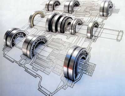
pictured: axle box railway node;
Below are shown: installation of p / w in the mechanism assembly; ball radial p/w.

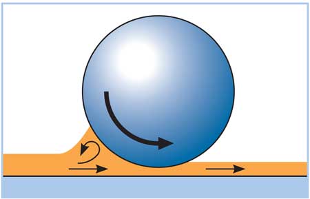
Rolling resistance diagrams.
SLIDE BEARING:
The support of the rotating (moving) part of the mechanism operating under the conditions of prevailing SLIDING FRICTION. (f / w, in which the view relative motion is slip). It usually consists of a sleeve or liner (hollow cylinder) made of anti-friction material, installed in the housing. Grease is supplied to the gap between the shaft and the bushing bore.

The calculation determines the minimum thickness of the lubricating layer, the pressure in the gap, the consumption of the lubricant, the temperature regime of the p / w. The selection and calculation is regulated by GOST, technical conditions and reference books. Depending on the design and operating requirements, sliding friction can be dry, boundary, liquid. But even a s/w with liquid friction at start-up passes through the boundary friction mode.
Lubrication is one of the main conditions for the operation of p / w sliding to ensure low friction between the moving parts of the mechanism, heat removal.
Lubrication types:
Hard (ex: graphite)
Plastic (calcium sulfate)
Liquid (oil, water)
Classificationp/w:
By shape (single, multi-surface)
By load (statically, dynamically loaded)
In the direction of the load (radial, thrust or thrust bearings, radial-thrust)
By lubrication supply (hydro / gas-dynamic: lubrication into the gap is drawn by the rotation of the shaft; hydro / gas-static: lubrication enters the gap under external (compressor) pressure).
Materials:
Metals: copper-based alloys (bronze, babbitt (a friction-reducing alloy based on tin or lead, intended for use as a layer, poured or sprayed on the bearing shell), brass), cast iron (the presence of free graphite in cast iron).
Non-metals: ceramics, polymers; wood-resinous, wood (birch, oak, boxwood, used in astronautics).
At present, the so-called self-lubricating p / w, manufactured by the method of powder metallurgy (powder sintering on the basis of metal under pressure and high temperature). When working from friction, this porous p / w, impregnated with fusible material or oil, heats up and releases lubricant. At rest, the p / w cools down, the pores shrink and absorb the lubricant back by the capillary method.
Advantages of p / w sliding:
High speed with static (under pressure) lubrication
Simplicity of design in low-speed mechanisms
Small radial dimensions
Gap adjustment
Disadvantages of p / w sliding:
Critical lubrication requirements (supply, flow, cleanliness, temperature)
Big losses friction at start-up and poor lubrication
Large axial dimensions
Limited operating temperature range (up to 250°C)
Uneven wear of the p / w and trunnion (part of the shaft or axis on which the support (bearing) is located) of the shaft.
| Lubrication supply |

dynamic lubrication. Static lubricant.
BEARING COMPARISON
| characteristics |
p/w slip |
p/w rolling |
|||
| Axial size(width) |
significant (up to 2 feet of shaft) |
small (up to 1 f shaft) |
|||
| Radial (max. dia.) |
Small (up to 1.5 lb shaft) |
significant (up to 3 feet of shaft) |
|||
| Usually 1.5-2 times higher |
|||||
| Price |
|||||
| small and medium sizes |
Moderate |
Low in mass production |
|||
| large sizes |
Moderate |
||||
| Preparation method |
As a rule, by the forces of the enterprises themselves with the order of the relevant materials |
Specialized bearing factories |
|||
| Required manufacturing precision |
Moderate |
||||
| Load bearing capacity: |
|||||
| Uncertain direction |
Excellent |
||||
| Cyclic |
Excellent |
||||
| Starting |
Excellent |
||||
| Satisfactory |
Satisfactory (cementable) |
||||
| Movement resistance |
|||||
| When starting off (starting) |
Less than 5-10 times |
||||
| At moderate speed |
Moderate |
Less than 2-4 times |
|||
| At very high speed and liquid lubricant(more than 10000 rpm,) |
(pressure lubrication) |
2-4 times higher |
|||
| Lubrication conditions |
|||||
| Lubrication types |
Oil, ointments, dry lubricants, air, water |
Oil, ointments |
|||
| Installation conditions |
|||||
| Conditions for creating self-aligning supports |
|||||
| Conditions for the running-in of new supports and the commissioning and commissioning. |
Long (in heavily loaded and high-speed units - tens of hours) |
Short (no more than a few hours) |
|||
Bibliography
GOST 520-2011 (Rolling bearings. General specifications);
GOST ISO 4378-1-2001 (Plain bearings. Terms, definitions and classification);
Rolling bearings: directory-catalogue / ed. V.N. Naryshkin and R.V. Korostoshevsky. Moscow: mashstroy 1984;
Big Soviet Encyclopedia 1978;
Rolling bearings are the most common standard products (assembly units) of many designs and modifications that are manufactured at specialized factories and built into more complex products (gearboxes, feed and speed boxes, machine tool spindles, etc.).
The main functional elements of a rolling bearing are rolling elements (balls or rollers) that roll along the raceways. The raceways are usually located on specially manufactured outer and inner rings of the bearing. The rolling elements are usually separated by a separator, which ensures that the rolling elements are evenly distributed around the circumference.
Bearings are classified according to the following criteria:
1) in the direction of the perceived load:
a) radial - perceive the load acting perpendicular to the axis of rotation of the bearing,
b) persistent - perceive the axial load,
c) radial-thrust - perceive the combined (radial and axial) load;
2) according to the shape of the rolling elements:
a) ball - with spherical rolling elements,
b) roller - with cylindrical, conical and barrel-shaped rolling elements;
3) by the number of rows of rolling elements:
a) single row
b) double row,
c) multi-row;
4) by the presence of seals and protective washers:
a) open - without seals and protective washers,
b) closed - with one or two seals, with one or two protective washers or one seal and one protective washer.
The standards establish the following series of bearings: extra light, extra light, light, light wide, medium, medium wide, heavy. Bearings of various series differ from each other in size, limiting revolutions per minute, static and dynamic load capacity and other parameters.
GOST 3189-89 “Ball and roller bearings. Designation system ”sets the types of bearings given with the indication of the designations established by the standard.
|
Bearing types |
Notation |
|
Ball radial |
|
|
Ball radial spherical |
|
|
Roller radial with short cylindrical rollers |
|
|
Roller radial with spherical rollers |
|
|
Roller radial with long cylindrical or needle rollers |
|
|
Roller radial with twisted rollers |
|
|
Ball angular contact |
|
|
Roller conical |
|
|
Ball thrust, ball thrust-radial |
|
|
Roller thrust, roller thrust-radial |
The designation of the bearing includes the code designations of the series, type, design features, category and diameter of the connecting hole of the bearing (diameter of the shaft mating with this bearing). Full designation standard bearing includes nine positions in which, counting from right to left, are encoded:
diameter of the connecting bore of the bearing (positions one and two);
a series of bearing diameters (third position);
bearing type (fourth position);
design features (fifth and sixth positions);
a series of bearing widths (seventh position);
bearing accuracy class (the eighth position is separated from the seventh by a dash);
The bearing bore diameter for bearings with bore diameters from 20 to 495 mm is indicated by a number that is the quotient of the diameter divided by 5, for bearings with bore diameters from 10 to 17 mm, the designations are as given below.
Table Designation of the diameter of the connecting hole
bearings with bore diameters from 10 to 17 mm
| d | 10 | 12 | 15 | 17 |
| Designation | 00 | 01 | 02 | 03 |
For bearings up to 9 mm in diameter, the first position indicates the actual inside diameter in millimeters. In this case, the third place from the right in the designation is 0.
For the most commonly used series, types and design features of the bearing, zeros are used as code digits, which are not indicated in the legend if there are no other digits on the left. For example, Bearing 205 GOST 8338 is a single-row radial bearing of normal accuracy class, light series, with a hole diameter of 25 mm. Only three positions on the right are used in the designation, since the remaining four positions are formally occupied by zeros.
The accuracy class of the rolling bearing is indicated before the symbol of the bearing number, separating it with a dash, for example: Bearing 6-205 GOST 8338 (the same bearing of the sixth accuracy class). The most common bearing accuracy classes (classes "normal" and 0) with their symbolic designation by zero in the bearing category designation WITH do not indicate.
For ball radial and angular contact bearings and for roller radial bearings GOST 520 “Rolling bearings. General Specifications” establishes the following accuracy classes: 8, 7, normal, 6, 5, 4, T, 2 (the designations are listed in ascending order of accuracy).
For roller tapered bearings accuracy classes 8, 7, 0, normal, 6X, 6, 5, 4, 2 are set.
The “normal” accuracy class for all bearings, except for tapered bearings, is denoted by the sign 0. For tapered bearings, the zero accuracy class is denoted by the sign 0, and the normal one by the letter N. To indicate the accuracy class 6X, use the sign X.
Bearings of accuracy classes 7 and 8 are made to order with reduced requirements for the accuracy of rotation of parts. Accuracy standards for such bearings are established in separate technical regulations.
Depending on the presence of requirements for the vibration level, the permissible values of the vibration level or the level of other additional technical requirements, three categories of bearings are established in GOST 520-2002 - A, IN, WITH.
Category A include bearings of accuracy classes 5, 4, T, 2, meeting increased additional requirements governing the standards for the level of vibration, waviness and deviations from the roundness of the rolling surfaces, the values of axial and radial runout, corresponding to the following more high class accuracy, friction torque and contact angle.
Category IN include bearings of accuracy classes 0, normal, 6X, 6, 5, meeting increased additional requirements governing the standards for the level of vibration, waviness and deviations from the roundness of rolling surfaces, axial and radial runout values corresponding to the next higher accuracy class, friction torque and contact angle , height, mounting height and width of the bearings.
Category WITH include bearings of accuracy classes 8, 7, 0, normal, 6, which are not subject to Additional requirements set for bearing categories A And IN.
Specific values of additional technical requirements are set in normative documents for bearings of categories A, IN, WITH or in the design documentation approved in the prescribed manner.
Examples of designations (without indicating the word "bearing" and the number of the standard or TS) with indications of accuracy classes:
A5-307; 205; X-307; N-97510.
The sign 0 is included in the designation only if there is also a marking sign to the left of it, for example B0-205.
The main indicators of the accuracy of bearings and their parts are:
dimensional accuracy of the connecting surfaces ( d, dm, D, Dm). Normalize the average diameters ( dm, dm) external or internal nominally cylindrical connecting surface, in order to limit such form deviations as ovality and tapering, which are most unfavorable for the bearing. The average diameter is determined by calculation as the arithmetic mean of the largest and smallest diameter values measured in several sections of the ring;
the accuracy of the shape and location of the surfaces of the rings (radial and end runout, the variability of the width of the rings) and the roughness of their surfaces;
the accuracy of the shape and size of the rolling elements;
lateral runout along the raceways of the inner and outer rings.
These indicators determine the uniformity of the distribution of the load on the rolling elements, the accuracy of rotation, therefore (together with the physical and mechanical properties), and the service life of the bearing.
The standard interface of a bearing with mating parts is formed as a combination of tolerance fields for connecting dimensions of bearing rings with standard tolerance fields for shafts and holes.
 |
|||
|
 |
|||
 |
|||
Tolerance field layouts:
a) tolerance fields for shaft fits in the inner ring of the bearing;
b) tolerance fields for fitting the outer ring of the bearing into the housing
The location of the tolerance fields of the mounting dimensions of the bearing rings is standardized in such a way as to obtain the necessary combinations with the standard tolerance fields, which are most often used in general engineering. The tolerance field of the hole of the inner ring of the bearing is located one-sided from the face value in the "air", and not in the "part body" (as is customary for the main hole). As a result, the combination of such a tolerance field of the bearing hole with the tolerance fields of mating shafts of the type k 6,m 6 or n 6 gives interference fits, while with the main hole such tolerance fields give transitional fits.
The choice of tolerance fields for the surfaces of shafts and housings associated with bearing rings is regulated by GOST 3325-85 “Rolling bearings. Tolerance fields and technical requirements to the seating surfaces of shafts and housings. Landings". This standard applies to the seating surfaces of shafts and housing bores for rolling bearings that meet the following requirements:
1. Steel shafts, solid or hollow, thick-walled, i.e. with a ratio d/db≥ 1.25, where d- shaft diameter, db is the diameter of the hole in it.
2. Body material - steel or cast iron.
3. Heating temperature of bearings during operation is not higher than 100 °C.
The choice of fit of the bearing ring (the choice of tolerance fields for shafts and housing holes mating with bearing rings) is carried out taking into account:
type of loading of the bearing ring;
operating mode of the bearing;
equivalent load ratio R and catalog dynamic load rating WITH;
type, size and accuracy class of the bearing.
There are three main types of loading of the bearing rings: local (M), circulation (C) and oscillatory (K).
Under local loading, the ring perceives a constant radial force in the direction of a limited section of the circumference of the raceway and transfers it to the corresponding section of the seating surface of the shaft or housing. This type of loading occurs, for example, when the stationary ring is loaded with a constant radial force in the direction (outer rings of the bearing supports of the shafts in the gearbox, etc.).
Under circulating loading, the ring perceives the radial force sequentially by all elementary sections of the circumference of the raceway and, accordingly, transfers it to the entire seating surface of the shaft or housing. Such loading occurs when the ring rotates against a fixed radial force acting on it (for example, the inner bearing ring on the rotating shaft of the gearbox) or the force circulates and the ring is stationary (for example, the inner bearing ring of a fixed differential gear sun wheel).
Under oscillatory loading, two radial forces integrally act on the fixed ring (one is constant in direction, and the other, smaller in value, circulates). The resultant load does not make a full turn, but oscillates between the extreme points of the circular arc.
For a ring that experiences circulation loading, an interference fit is assigned. The presence of a gap between the circulation-loaded ring and the seating surface of the part can lead to the rotation of the ring with slippage of the surfaces, and, consequently, to flaring and abrasion of the metal of the part, which is unacceptable.
The main danger for a ring that experiences local loading is the wear of the raceway at the place of the load. If a clearance fit is assigned to this ring and if it is not fixed in the axial direction, then under the influence of vibration and shocks it gradually rotates along the seating surface. As a result, the wear of the raceway occurs more evenly around the entire circumference of the ring.
It can be proposed to choose landings so that the circulation or vibrationally loaded (usually rotating) bearing ring is mounted with an interference fit, which excludes the possibility of this ring slipping along the mating surface of the shaft or hole in the housing. Another ring of the same bearing, if locally loaded, may be seated with clearance. With this combination of landings of the rings of one bearing, the risk of jamming of the rolling elements due to an excessive decrease in the radial clearance is eliminated.
The operating mode of the rolling bearing according to GOST 3325 is characterized by the calculated durability and ratio R/S, Where R- equivalent load (conditional constant load, providing the same bearing life as it should be in actual conditions); WITH– dynamic load rating (constant radial load corresponding to the estimated service life):
· easy mode work - R/S ≤ 0,07;
· normal mode work - 0.07 R/S ≤ 0,15;
· heavy duty work - R/S 0,15.
Estimated durability corresponding to the modes of operation:
heavy - from 2500 to 5000 hours;
normal - from 5000 to 10000 hours;
light - more than 10,000 hours.
The choice of qualifications that determine the accuracy of manufacturing the shaft trunnion and the hole in the housing for fitting the rolling bearing is carried out depending on the accuracy class of the bearing. For example, if the accuracy class of the bearing is 0, normal or 6th, the hole in the housing is made according to the 7th (less often 6th) quality, and the shaft - according to the 6th (less often 5th) quality, etc.
When the bearing rings are deformed, the radial clearance decreases, which can eventually lead to jamming of the rolling elements. After selecting the landings and determining the tightness (clearances) according to connecting dimensions it is necessary to check the presence of a radial clearance in the rolling bearing after it has been seated in the housing or on the shaft with an interference fit:
![]() or
or ![]() ,
,
Where G noc – clearance in the rolling bearing after an interference fit;
Gr- initial radial clearance;
Δ d 1 - diametrical deformation of the treadmill of the inner ring when it is fitted with an interference fit;
Δ D 1 - diametrical deformation of the treadmill of the outer ring when it is fitted with an interference fit.
![]() ;
;
![]() ,
,
Where N ef is the effective preload, calculated as
![]() ;
;
d 0 is the reduced inner diameter of the bearing, calculated as
![]() ;
;
D 0 - reduced outside diameter bearing, calculated as
![]() ;
;
N ism - measured tightness before assembly (in theoretical calculations for N ism take the average interference as the most probable);
N cp = (N max + N min)/2 .
GOST 24810-81 “Rolling bearings. Clearances” defines clearance groups and their designations for bearings various types. So, for single-row radial ball bearings with a cylindrical bore, the standard establishes the following groups of clearances: 6, normal, 7, 8, 9th. Symbol radial clearance groups, except for the “normal” group, must be marked on the bearing to the left of the accuracy class designation.
If, by calculation, it is determined that the clearance in the bearing after the fit becomes an interference fit, the group should be changed in the direction of increasing the clearance or another fit with a reduced interference should be selected.
When controlling the linear dimensions of the bearing rings, the unit diameters of the holes of the inner rings and the unit diameters of the outer rings are measured. As a result, the values of single diameters and the average diameter, the values of the variability of the diameters, are obtained.
Single hole diameters of the inner rings are measured according to the diagrams below. For control in two cross sections, the bearing is placed on the end, then turned over and placed on the opposite end.

bearing inner ring
bearing outer ring
The control of the single width of the bearing rings is carried out according to the schemes given below.