Magnetic flux, flux of magnetic induction, flux Ф of the magnetic induction vector B through any surface. M. p. dФ through a small area dS, within which the vector B can be considered unchanged ...
Magnetic permeability, a physical quantity that characterizes the relationship between magnetic induction B and magnetic field H in a substance. It is denoted by m, for isotropic substances m \u003d B / N (in the CGS system of units) or m ...
International system of units (Systeme International d "Unitees"), a system of units of physical quantities adopted by the 11th General Conference on Weights and Measures (1960). The abbreviation for the system is SI ...
Henry, the unit of inductance and mutual inductance in the International System of Units and the ISSA system of units. Named after the American scientist J. Henry. Abbreviated designation: Russian gn ...
CGS system of units, a system of units of physical quantities, in which three basic units are accepted: length - centimeter, mass - gram and time - second. System with basic units of length, mass and…
Self-induction, the occurrence of an emf of induction in a conducting circuit when the current strength changes in it; a special case of electromagnetic induction. When the current in the circuit changes, the flux of magnetic induction changes ...
Inductance coil, an insulated conductor coiled into a spiral, which has a significant inductance with a relatively small capacitance and low active resistance. I. to. consists of a single-core ...
Ferromagnets, substances (usually in a solid crystalline state), in which, below a certain temperature (Curie point Q), the ferromagnetic order of the magnetic moments of atoms or ...
Magnetic constant, the coefficient of proportionality m0, which appears in a number of formulas of magnetism when written in a rationalized form (in the International System of Units). So, induction B magnetic field…
Inductance (from Latin inductio - guidance, motivation), a physical quantity that characterizes the magnetic properties of an electrical circuit. The current flowing in a conducting circuit creates a magnetic field in the surrounding space, and the magnetic flux Ф penetrating the circuit (linked to it) is directly proportional to the current strength I:
Proportionality factor L is called I. or the coefficient of self-induction of the circuit. I. depends on the size and shape of the contour, as well as on the magnetic permeability environment. In the International System of Units (SI) I. is measured in Henry, in the CGS system of units (Gauss) I. has the dimension of length and therefore the unit I. is called a centimeter (1 Mr = 109cm).
Through I., the emf of self-induction in the circuit, which occurs when the current changes in it, is expressed:
(D I- change in current over time D t). For a given current strength, I. determines the energy W magnetic field current:
The greater the I., the greater the magnetic energy accumulated in the space around the circuit with current. If we draw an analogy between electrical and mechanical phenomena, then the magnetic energy should be compared with the kinetic energy of the body T = mv 2/2 (where m- body mass, v- the speed of its movement), while I. will play the role of mass, and the current will play the role of speed. Thus, I. determines the inertial properties of the current.
In practice, sections of the circuit with significant I. are performed in the form of coil inductance. For increase L coils with iron cores are used, but in this case, due to the dependence of the magnetic permeability m of ferromagnets on the field strength and, consequently, on the current strength, I. becomes dependent on I. I. long solenoid out N coils having a cross-sectional area S and length l, in a medium with magnetic permeability m is (in SI units): L=mm0 N 2S/l, where m0 is the magnetic constant, or the magnetic permeability of vacuum.
Lit.: Kalashnikov S. G., Electricity, M., 1970 (General course of physics, vol. 2), ch. 9.
G. Ya. Myakishev.
Length and distance Mass Measures of volume of bulk products and foodstuffs Area Volume and units of measurement in culinary recipes Temperature Pressure, mechanical stress, Young's modulus Energy and work Power Force Time Linear velocity Flat angle Thermal efficiency and fuel efficiency Numbers Units of measurement of the amount of information Exchange rates Sizes of women's clothing and footwear Sizes of men's clothing and footwear Angular velocity and rotation frequency Acceleration Angular acceleration Density Specific volume Moment of inertia Moment of force Torque Specific calorific value (by mass) Energy density and specific calorific value of fuel (by volume) Temperature difference Coefficient of thermal expansion Thermal resistance Specific thermal conductivity Specific heat capacity Energy exposure, thermal radiation power Heat flux density Heat transfer coefficient volume flow Mass flow Molar flow Mass flow density Molar concentration Mass concentration in solution Dynamic (absolute) viscosity Kinematic viscosity Surface Tension Vapor Permeability Vapor Permeability, Vapor Transfer Rate Sound Level Microphone Sensitivity Sound Pressure Level (SPL) Brightness Light Intensity Illuminance Resolution in Computer Graphics Frequency and Wavelength Diopter Power and Focal Length Diopter Power and Lens Magnification (×) Electric Charge Linear charge density Surface charge density Bulk charge density Electric current Linear current density Surface current density Electric field strength Electrostatic potential and voltage Electrical resistance Electrical resistivity Electrical conductivity Electrical conductivity Electrical capacitance Inductance US wire gauge Levels in dBm (dBm or dBm), dBV ( dBV), watts, etc. units Magnetomotive force Magnetic field intensity Magnetic flux Magnetic induction Absorbed dose rate of ionizing radiation Radioactivity. Radioactive decay Radiation. Exposure dose Radiation. Absorbed dose Decimal prefixes Data transmission Typography and image processing Timber volume units Calculation of molar mass Periodic system of chemical elements of D. I. Mendeleev
1 microhenry [µH] = 1E-06 henry [H]
Initial value
Converted value
henry exagenry petagenry terahenry gigahenry megahenry kilohenry hectogenry decahenry centihenry millihenry microhenry nanohenry picogenry femtogenry attogenry weber/amp abhenry CGSM inductance unit stathenry CGSE inductance unit
Featured Article
More about inductance
Introduction
If someone came up with the idea to conduct a survey of the population of the Earth on the topic “What do you know about inductance?”, Then the vast majority of respondents would simply shrug their shoulders. But this is the second most numerous technical element after transistors, on which modern civilization is based! Detective lovers, remembering that in their youth they read the exciting stories of Sir Arthur Conan Doyle about the adventures of the famous detective Sherlock Holmes, with varying degrees certainty will mutter something about the method the said detective used. At the same time, implying the method of deduction, which, along with the method of induction, is the main method of cognition in Western philosophy of modern times.
With the method of induction, the study of individual facts, principles and the formation of general theoretical concepts based on the results obtained (from the particular to the general) take place. The deductive method, on the contrary, involves the study of general principles, laws, when the provisions of the theory are distributed into separate phenomena.
It should be noted that induction, in the sense of the method, does not have any direct relation to inductance, they just have a common Latin root induction- guidance, motivation - and denote completely different concepts.
Only a small part of the respondents from among the bearers of the exact sciences - professional physicists, electrical engineers, radio engineers and students of these areas - will be able to give a clear answer to this question, and some of them are ready to read a whole lecture on this topic on the go.
Definition of inductance
In physics, inductance, or the coefficient of self-induction, is defined as the coefficient of proportionality L between the magnetic flux Ф around the current-carrying conductor and the current I generating it, or - in a stricter formulation - this is the coefficient of proportionality between electric current ohm, current in any closed circuit, and the magnetic flux created by this current:
Ф = L∙I
L = F / I
To understand the physical role of an inductor in electrical circuits, one can use the analogy of the formula for the energy stored in it when current I flows, with the formula for the mechanical kinetic energy of a body.
For a given current I, the inductance L determines the energy of the magnetic field W created by this current I:
Similarly, the mechanical kinetic energy of a body is determined by the mass of the body m and its speed V:
That is, inductance, like mass, does not allow the energy of the magnetic field to increase instantly, just as the mass does not allow doing this with the kinetic energy of the body.
Let's study the behavior of the current in the inductance:
Due to the inertia of the inductance, the fronts of the input voltage are pulled. Such a circuit in automation and radio engineering is called an integrating circuit, and is used to perform the mathematical operation of integration.
Let's study the voltage on the inductor:
At the moments of applying and removing voltage, due to the self-induction EMF inherent in inductance coils, voltage surges occur. Such a circuit in automation and radio engineering is called a differentiating circuit, and is used in automation to correct processes in a controlled object that are of a fast nature.
Units
In the SI system, inductance is measured in henries, abbreviated as H. A circuit with current has an inductance of one henry if, when the current changes by one ampere per second, a voltage of one volt will appear at the circuit terminals.
In variants of the CGS system - the CGSM system and in the Gaussian system, the inductance is measured in centimeters (1 H \u003d 10⁹ cm; 1 cm \u003d 1 nH); for centimeters, the name abhenry is also used as a unit of inductance. In the CGSE system, the unit of inductance is either left unnamed or sometimes called the stathenry (1 stathenry ≈ 8.987552 10⁻¹¹ henry, the conversion factor is numerically equal to 10⁻⁹ of the square of the speed of light expressed in cm/s).
Historical reference
The symbol L, used for inductance, was adopted in honor of Emil Khristianovich Lenz (Heinrich Friedrich Emil Lenz), who is known for his contribution to the study of electromagnetism, and who derived Lenz's rule about the properties of induced current. The unit of inductance is named after Joseph Henry, who discovered self-induction. The term inductance itself was coined by Oliver Heaviside in February 1886.
Among the scientists who took part in researching the properties of inductance and developing its various applications, it is necessary to mention Sir Henry Cavendish, who conducted experiments with electricity; Michael Faraday, who discovered electromagnetic induction; Nikola Tesla, who is known for his work on electrical transmission systems; André-Marie Ampere, who is considered the discoverer of the theory of electromagnetism; Gustav Robert Kirchhoff, who researched electrical circuits; James Clark Maxwell, who studied electromagnetic fields and their particular examples: electricity, magnetism and optics; Henry Rudolph Hertz, who proved that electromagnetic waves really exist; Albert Abraham Michelson and Robert Andrews Milliken. Of course, all these scientists have also explored other problems that are not mentioned here.
Inductor
By definition, an inductor is a helical, helical, or helical coil of coiled insulated conductor that has significant inductance with relatively low capacitance and low active resistance. As a result, when an alternating electric current flows through the coil, its significant inertia is observed, which can be observed in the experiment described above. In high-frequency technology, an inductor can consist of one turn or part of it; in the limiting case, at microwave frequencies, a piece of conductor is used to create inductance, which has a so-called distributed inductance (strip lines).
Application in technology
Inductors are used:
- For interference suppression, ripple smoothing, energy storage, limiting alternating current, in resonant (oscillating circuit) and frequency-selective circuits; creating magnetic fields, motion sensors, in credit card readers, as well as in the contactless credit cards themselves.
- Inductors (together with capacitors and resistors) are used to build various circuits with frequency-dependent properties, in particular filters, circuits feedback, oscillatory circuits and others. Such coils, respectively, are called so: contour coil, filter coil, and so on.
- Two inductively coupled coils form a transformer.
- Inductor fed impulse current from a transistor key, sometimes used as a source high voltage low power in low-current circuits, when creating a separate high supply voltage in the power supply is impossible or not economically feasible. In this case, high voltage surges occur on the coil due to self-induction, which can be used in the circuit.
- When used for interference suppression, smoothing of electric current ripples, isolation (decoupling) high frequency different parts of the circuit and the accumulation of energy in the magnetic field of the core, the inductor is called a choke.
- In power electrical engineering (to limit the current at, for example, short circuit Power line) the inductor is called the reactor.
- The current limiters of welding machines are made in the form of an inductor, limiting the current of the welding arc and making it more stable, thereby allowing you to get a more even and durable welding seam.
- Inductors are also used as electromagnets - executive mechanisms. A cylindrical inductor whose length is much greater than the diameter is called a solenoid. In addition, a solenoid is often called a device that performs mechanical work due to the magnetic field when the ferromagnetic core is pulled in.
- In electromagnetic relays, inductors are called relay windings.
- Heating inductor - a special inductor, the working body of induction heating installations and kitchen induction ovens.
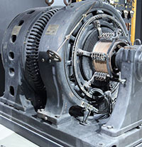
By by and large, in all electric current generators of any type, as well as in electric motors, their windings are inductors. Following the tradition of the ancients depicting a flat Earth standing on three elephants or whales, today we could argue with good reason that life on Earth rests on an inductor.
After all, even the Earth's magnetic field, which protects all terrestrial organisms from corpuscular cosmic and solar radiation, according to the main hypothesis about its origin, is associated with the flow of huge currents in the liquid metal core of the Earth. In fact, this core is a planetary scale inductor. It is calculated that the zone in which the "magnetic dynamo" mechanism operates is located at a distance of 0.25-0.3 of the Earth's radius.
Rice. 7. Magnetic field around a conductor with current. I- current, B- vector of magnetic induction.
Experiences
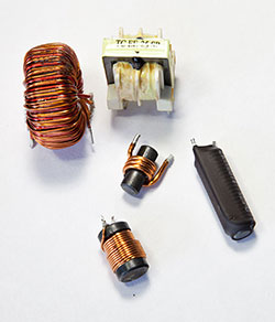
In conclusion, I would like to talk about some of the curious properties of inductors that you could observe for yourself, having at hand the simplest materials and available devices. To conduct experiments, we need pieces of insulated copper wire, a ferrite rod and any modern multimeter with the function of measuring inductance. Recall that any conductor with current creates around itself a magnetic field of this kind, shown in Figure 7.
We wind four dozen turns of wire on a ferrite rod with a small step (the distance between the turns). This will be reel #1. Then we wind the same number of turns with the same pitch, but with the reverse direction of winding. This will be coil #2. And then we wind 20 turns in an arbitrary direction close. This will be coil #3. Then carefully remove them from the ferrite rod. The magnetic field of such inductors looks something like the one shown in Fig. 8.
Inductors are divided mainly into two classes: with a magnetic and non-magnetic core. Figure 8 shows a coil with a non-magnetic core, air plays the role of a non-magnetic core. On fig. 9 shows examples of inductors with a magnetic core, which can be closed or open.
Ferrite cores and electrical steel plates are mainly used. Cores increase the inductance of the coils at times. Unlike cylinder-shaped cores, ring-shaped (toroidal) cores allow you to get large inductance, since the magnetic flux in them is closed.
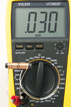
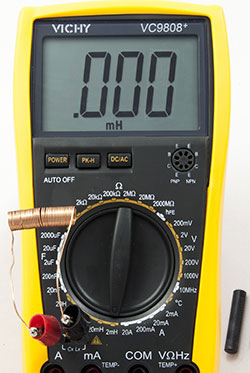
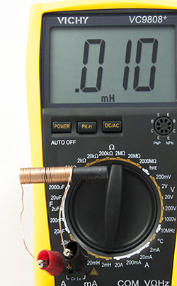
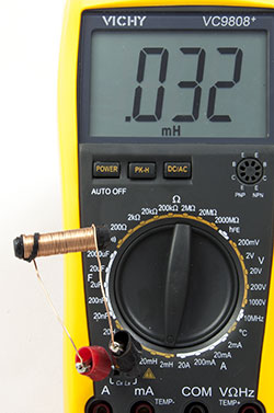
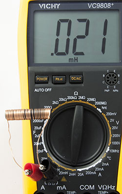
Let's connect the ends of the multimeter, included in the inductance measurement mode, to the ends of coil No. 1. The inductance of such a coil is extremely small, on the order of a few fractions of a microhenry, so the device does not show anything (Fig. 10). Let's start introducing a ferrite rod into the coil (Fig. 11). The device shows about a dozen microhenries, and when the coil moves to the center of the rod, its inductance increases by about three times (Fig. 12).
As the coil moves to the other end of the rod, the value of the coil inductance drops again. Conclusion: the inductance of the coils can be adjusted by moving the core in them, and its maximum value is achieved when the coil is located on the ferrite rod (or, conversely, the rod in the coil) in the center. So we got a real, albeit somewhat awkward, variometer. Having done the above experiment with coil No. 2, we will get similar results, that is, the winding direction does not affect the inductance.
Let's lay the turns of the coil No. 1 or No. 2 on the ferrite rod more tightly, without gaps between the turns, and measure the inductance again. It increased (Fig. 13).
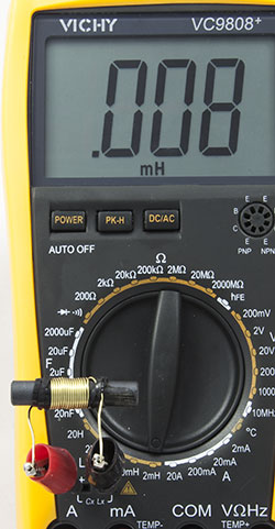
And when the coil is stretched along the rod, its inductance decreases (Fig. 14). Conclusion: by changing the distance between the turns, you can adjust the inductance, and for maximum inductance, you need to wind the coil “turn to turn”. The method of adjusting the inductance by stretching or compressing the turns is often used by radio engineers, tuning their transceiver equipment to the desired frequency.
Let's install coil No. 3 on the ferrite rod and measure its inductance (Fig. 15). The number of turns has been halved and the inductance has been halved. Conclusion: the smaller the number of turns, the lower the inductance, and there is no linear relationship between the inductance and the number of turns.
Do you find it difficult to translate units of measurement from one language to another? Colleagues are ready to help you. Post a question to TCTerms and within a few minutes you will receive an answer.
Designation and units of measurement
In the SI system, inductance is measured in henry, abbreviated Hn, in the CGS system - in centimeters (1 H \u003d 10 9 cm). A circuit has an inductance of one henry if, when the current changes by one ampere per second, a voltage of one volt will appear at the circuit terminals. A real, not superconducting, circuit has an ohmic resistance R, therefore, an additional voltage U = I * R will appear on it, where I is the strength of the current flowing through the circuit at a given instant of time.
The symbol used to denote inductance was taken in honor of Emil Khristianovich Lenz (Heinrich Friedrich Emil Lenz) [ source not specified 1017 days] . The unit of inductance is named after Joseph Henry. The term inductance itself was proposed by Oliver Heaviside in February 1886 [ source not specified 1017 days] .
An electric current that flows in a closed circuit creates a magnetic field around itself, the induction of which, according to the Biot-Savart-Laplace law, is proportional to the current. The magnetic flux coupled to the circuit Ф is therefore directly proportional to the current I in the circuit:
where the proportionality factor L is called loop inductance.
When the current strength changes in the circuit, the magnetic flux coupled to it will also change; this means that emf will be induced in the circuit. Emf occurrence. induction in a conducting circuit when the current strength changes in it is called self-induction.
From expression (1) the unit of inductance is set Henry(H): 1 H - the inductance of the circuit, the magnetic flux of self-induction of which at a current of 1 A is 1 Wb: 1 Hn \u003d 1 Wb / s \u003d 1 V
Let us calculate the inductance of an infinitely long solenoid. The total magnetic flux through the solenoid (flux linkage) is μ 0 μ(N 2 I/ l)S . Substituting into (1), we find
i.e. the inductance of the solenoid depends on the length l solenoid, the number of its turns N, its area S and magnetic permeability μ of the substance from which the solenoid core is made.
It is proved that the inductance of the circuit depends on general case only on the geometric shape of the circuit, its dimensions and the magnetic permeability of the medium in which it is located, and it is possible to draw an analogue of the inductance of the circuit with the electric capacitance of a solitary conductor, which also depends only on the shape of the conductor, its dimensions and the dielectric constant of the medium.
Let us find, applying the Faraday law to the phenomenon of self-induction, that emf. self-induction is equal to
If the contour does not undergo deformations and the magnetic permeability of the medium remains unchanged (it will be shown below that the latter condition is not always satisfied), then L = const and
where the minus sign, determined by Lenz's rule, says that the presence of inductance in the circuit leads to a slowdown in the change in current in it.
If the current increases with time, then (dI/dt<0) и ξ s >0 i.e., the self-induction current is directed towards the current due to external source, and slows down its growth. If the current decreases with time, then (dI/dt>0) and ξ s<0 т. е. индукционный ток имеет такое же направление, как и уменьшающийся ток в контуре, и замедляет его уменьшение. Значит, контур, обладая определенной индуктивностью, имеет электрическую инертность, заключающуюся в том, что любое изменение тока уменьшается тем сильнее, чем больше индуктивность контура.
42. Current when opening and closing the circuit.
With any change in the current strength in a conducting circuit, an e. d.s. self-induction, as a result of which additional currents appear in the circuit, called extra currents of self-induction. The extracurrents of self-induction, according to Lenz's rule, are always directed in such a way as to prevent changes in the current in the circuit, that is, they are directed opposite to the current created by the source. When the current source is turned off, the extra currents have the same direction as the weakening current. Therefore, the presence of inductance in the circuit leads to a slowdown in the disappearance or establishment of current in the circuit.
Consider the process of turning off the current in a circuit containing a current source with an emf. , resistor resistance R and an inductor L. Under the influence of external e. d.s. direct current flows in the circuit
(we neglect the internal resistance of the current source).
At the point in time t=0 turn off the current source. Current in the inductor L will begin to decrease, which will lead to the emergence of emf. self-induction preventing, according to Lenz's rule, a decrease in current. At each moment of time, the current in the circuit is determined by the Ohm law I= s/R, or
Dividing the variables in expression (127.1), we obtain Integrating this equation over I(from I 0 to I) And t(from 0 to t), we find ln ( I/I 0) = -RT/L, or
where t= L/R- constant called relaxation time. From (127.2) it follows that t is the time during which the current strength decreases by e times.
Thus, in the process of turning off the current source, the current strength decreases according to the exponential law (127.2) and is determined by the curve 1 in fig. 183. The greater the inductance of the circuit and the lower its resistance, the greater t and, therefore, the slower the current in the circuit decreases when it is opened.
When the circuit is closed, in addition to the external e. d.s. e occurs. d.s. self-induction, which, according to Lenz's rule, prevents the increase in current. Ohm's law, or
By introducing a new variable, we transform this equation to the form
where t is the relaxation time.
At the moment of closing ( t=0) current I= 0 and u= - . Therefore, integrating over And(from to IR–) And t(from 0 to t), find ln[( IR– )]/– = -t/t, or
where is the steady current (at t®¥).
Thus, in the process of switching on the current source, the increase in the current strength in the circuit is given by the function (127.3) and is determined by curve 2 in Fig. 183. The strength of the current increases from the initial value I= 0 and asymptotically tends to the steady value . The current rise rate is determined by the same relaxation time t=L/R, which is the decrease in current. The current is established the faster, the smaller the inductance of the circuit and the greater its resistance.
Let us estimate the emf value. self-induction arising from an instantaneous increase in the resistance of a DC circuit from R 0 to R. Suppose we open the circuit when a steady current flows in it. When the circuit is opened, the current changes according to the formula (127.2). Substituting into it the expression for I 0 and t, we get
emf self-induction
![]()
i.e. with a significant increase in circuit resistance (R/R 0 >>1), which has a large inductance, e.m.f. self-induction can many times exceed emf. current source included in the circuit. Thus, it must be taken into account that the circuit containing the inductance cannot be abruptly opened, since this (the appearance of significant emfs of self-induction) can lead to insulation breakdown and failure measuring instruments. If resistance is introduced into the circuit gradually, then emf. self-induction will not reach large values.
43. The phenomenon of mutual induction. Transformer.
Consider two fixed circuits (1 and 2), which are located fairly close to each other (Fig. 1). If current I 1 flows in circuit 1, then the magnetic flux that is created by this current (the field that creates this flux is shown in the figure by solid lines) is directly proportional to I 1. Let us denote by Ф 21 the part of the flow penetrating circuit 2. Then
where L 21 - coefficient of proportionality.
Fig.1
If the current I 1 changes its value, then emf is induced in circuit 2. ξ i2, which, according to Faraday's law, will be equal and opposite in sign of the rate of change of the magnetic flux Ф 21, which is created by the current in the first circuit and permeates the second:
Similarly, when current I 2 flows in circuit 2, the magnetic flux (its field is shown in Fig. 1 with dashes) permeates the first circuit. If F 12 is part of this flow, which permeates circuit 1, then
If the current I 2 changes its value, then emf is induced in circuit 1. ξ i1, which is equal and opposite in sign of the rate of change of the magnetic flux Ф 12, which is created by the current in the second circuit and permeates the first one:
The phenomenon of emf occurrence. in one of the circuits when the current strength changes in the other is called mutual induction . The coefficients of proportionality L 21 and L 12 are called mutual inductance of circuits. Calculations, which are confirmed by experience, show that L 21 and L 12 are equal to each other, i.e.
The coefficients of proportionality L 12 and L 21 depend on the dimensions, geometric shape, relative position of the contours and on the magnetic permeability of the medium surrounding the contours. The unit of mutual inductance is the same as for inductance - henry (H).
Find the mutual inductance of two coils that are wound on a common toroidal core. This case is of great practical importance (Fig. 2). The magnetic induction of the field, which is created by the first coil with the number of turns N 1, the current I 1 and the magnetic permeability μ of the core, B = μμ 0 (N 1 I 1 / l) Where l- the length of the core along the midline. Magnetic flux through one turn of the second coil Ф 2 = BS = μμ 0 (N 1 I 1 / l)S
This means that the total magnetic flux (flux linkage) through the secondary winding, which contains N 2 turns,
The flow Ψ is created by the current I 1 , therefore, using (1), we find
If we calculate the magnetic flux that is created by coil 2 through coil 1, then for L 12 we obtain an expression in accordance with formula (3). This means that the mutual inductance of two coils that are wound on a common toroidal core,
Transformer(from lat. transformo- convert) is a static electromagnetic device that has two or more inductively coupled windings on any magnetic circuit and is designed to convert one or more AC systems (voltages) into one or more other AC systems (voltages) by means of electromagnetic induction without changing the frequency AC system (voltage)
Faraday's Law
See also: Electromagnetic induction
The EMF generated in the secondary winding can be calculated from Faraday's law, which states that:
![]()
U 2- Voltage on the secondary winding,
N 2- number of turns in the secondary winding,
Φ - total magnetic flux, through one turn of the winding. If the turns of the winding are perpendicular to the lines of the magnetic field, then the flux will be proportional to the magnetic field B and square S through which it passes.
EMF generated in the primary winding, respectively:
![]()
U 1- instantaneous value of voltage at the ends of the primary winding,
N 1 is the number of turns in the primary winding.
Dividing the equation U 2 on U 1, we get the ratio:
44. Energy of the magnetic field, its density.
A conductor with an electric current flowing through it is always surrounded by a magnetic field, and the magnetic field disappears and appears along with the disappearance and appearance of the current. A magnetic field, like an electric field, is a carrier of energy. It is logical to assume that the energy of the magnetic field coincides with the work expended by the current to create this field.
Consider a circuit with inductance L, through which current I flows. Magnetic flux Ф=LI is coupled to this circuit, since the inductance of the circuit is unchanged, then when the current changes by dI, the magnetic flux changes by dФ=LdI. But to change the magnetic flux by the value dФ, the work dА=IdФ=LIdI should be done. Then the work to create a magnetic flux Ф is equal to
![]()
This means that the energy of the magnetic field, which is associated with the circuit,
The energy of a magnetic field can be considered as a function of the quantities that characterize this field in the surrounding space. To do this, consider a special case - a uniform magnetic field inside a long solenoid. Substituting the solenoid inductance formula into formula (1), we find
![]()
Since I=B l/(μ 0 μN) and B \u003d μ 0 μH, then
![]() (2)
(2)
where S l= V is the volume of the solenoid.
The magnetic field inside the solenoid is homogeneous and concentrated inside it, therefore the energy (2) is contained in the volume of the solenoid and has a uniform distribution with it with a constant bulk density
Formula (3) for the volumetric energy density of a magnetic field has a form similar to the expression for the volumetric energy density of an electrostatic field, with the difference that electrical quantities are replaced in it by magnetic ones. Formula (3) was derived for a homogeneous field, but it is also true for inhomogeneous fields. Formula (3) is valid only for media for which linear dependence B from H, i.e. it applies only to para- and diamagnets.
45. Magnetic field in matter. Magnetization. Magnetic permeability. The strength of the magnetic field, its relationship with magnetic induction.


