The world's first mass-produced car with an engine powered by compressed air, was released by the Indian company Tata, known throughout the world for the production of cheap Vehicle for poor people.
The Tata OneCAT car weighs 350 kg and can travel 130 km on one supply of air compressed to a pressure of 300 atmospheres, while accelerating up to 100 kilometers per hour. But such indicators are possible only with the maximum filled tanks. The lower the air density in them, the lower the indicator becomes. top speed.
4 cylinders made of carbon fiber with a Kevlar shell, 2 long and a quarter of a meter in diameter each, located under the bottom, contain 400 liters of compressed air at a pressure of 300 bar.
Inside, everything is very simple:
But this is understandable, since the car is positioned mainly for use in a taxi. By the way, the idea is not without interest - unlike electric vehicles with their problematic recyclable batteries and low efficiency of the charge-discharge cycle (from 50% to 70% depending on the level of charge and discharge currents), air compression, its storage in a cylinder and subsequent use is quite economical and environmentally friendly.
If you fill Tata car OneCAT by air at the compressor station, it will take three to four minutes. “Pumping” with the help of a mini-compressor built into the machine, powered by an outlet, lasts three to four hours. " air fuel” is relatively cheap: if you translate it into a gasoline equivalent, it turns out that the car consumes about a liter per 100 kilometers.
In an air car, there is usually no transmission - after all, the air motor produces maximum torque immediately - even when stationary. The air engine also requires virtually no maintenance, standard mileage between two technical inspections is no less than 100 thousand kilometers. And he practically does not need oil - a liter of "grease" is enough for the engine for 50 thousand kilometers (for ordinary car about 30 liters of oil will be required).
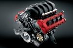
The secret of a new car is that it four-cylinder engine with a volume of 700 cubes and a weight of only 35 kilograms, it works on the principle of mixing compressed air with outside, atmospheric air. This power unit recalls conventional engine internal combustion, but its cylinders are of different diameters - two small, drive, and two large, working. When the engine is running outside air is sucked into small cylinders, compressed there by pistons and heated. Then it is pushed into two working cylinders and mixed there with cold compressed air coming from the tank. As a result air mixture expands and sets in motion the working pistons, and they - crankshaft engine.
Since no combustion takes place in the engine, only clean exhaust air will be its “exhaust gases”.
Developers air engine from MDI calculated the total energy efficiency in the chain "refinery - car" for three types drive - gasoline, electric and air. And it turned out that the efficiency of the air drive is 20 percent, which is two times once again exceeds the efficiency of a standard gasoline engine and one and a half times - the efficiency of the electric drive. In addition, compressed air can be stored directly for future use, using unstable renewable energy sources such as wind turbines - then the efficiency is even higher.
When the temperature drops to -20C, the energy reserve of the pneumatic drive is reduced by 10% without any other harmful effects for its operation, while the energy reserve of electric batteries will decrease by about 2 times.
By the way, the air used in the air motor has a low temperature and can be used to cool the car interior during the hot season, that is, you get air conditioning almost for free, without unnecessary energy costs. But the heater, alas, will have to be made autonomous. But this is much better than an electric car - which has to spend energy on both heating and cooling.
By the way, glass-carbon fiber cylinders are quite safe - if damaged, they do not explode, only cracks appear in them through which air escapes.
In most countries of the world, cars with internal combustion engines are still the main means of transportation. In the countries of the "golden billion", where the requirements for cars are much higher, the situation looks different - there cars running on electricity and other alternative fuels are now becoming the leading direction in production.
However, the emergence of an electric vehicle as a new standard in the automotive industry did not stop the initiative of scientists and developers of new types of vehicles.
Over the past twenty years, many different prototypes of cars have been created in the world: hydrogen fuel, biofuel, solar panels etc. However, it cannot be stated with certainty that any of these alternatives has real prospects to compete with the "traditional" ones. petrol cars and electric vehicles.
The problem here is that the decisive factor is always the simplicity and cheapness of production, and if Alternative option unprofitable, then all its other advantages are no longer of particular importance.
In such a situation, the experiments of large automotive companies are much more likely to be accepted and mass produced. An example of such a development is the Air Hybrid, an innovative hybrid unit consisting of an advanced internal combustion engine and a hydraulic compressor, designed and built by PSA. Peugeot Citroen.
This French concern, which combined the potential of two well-known automobile companies, set as its goal the creation of a new type of engine in which compressed air would be used instead of electricity. Air Hybrid has become a successful completion of the next stage of the company's program, which is aimed at reducing fuel consumption in brand cars to a record 2 liters per 100 kilometers.
The revolutionary nature of the Air Hybrid is that such an engine can operate in three modes at once - only on compressed air, on gasoline, and also on air and gasoline at the same time. One of the main advantages of this solution is a significant weight reduction, which in itself is also an important factor in fuel economy.
The hydraulic system not only weighs less, but is also much cheaper to manufacture than traditional system including batteries. In addition, hydraulics are more reliable - with it, many complex electronic systems, which in ordinary car too many and which control everything from starting the engine to the built-in breathalyzer.
It should be noted that the built-in professional breathalyzers that test the driver before starting the engine are a popular solution for many European manufacturers cars.
New hybrid engine from Peugeot Citroen consists of a gasoline engine, an adapted epicyclic type transmission, where a hydraulic compressor will be used instead of an electric motor.
In the prototype, under the floor of the car, there are two cylinders containing compressed air - one with low pressure air and the other with high pressure.
On compressed air, such a car can move at speeds up to 70 km / h, which is optimal for city trips. When you need to increase the speed, you can switch to Gas engine, and for extreme acceleration, the engines will work together.
Developed by the French Motor Company Development International (MDI) called the AIRPod is powered by compressed air. Although it has been produced since 2009, for a long time she evoked in everyone (with the possible exception of environmentalists) only an indulgent smile. Indeed, initially it could only be operated in a warm climate: the pneumatic propeller engine developed in the early 1990s did not start when low temperatures. And although today a compressed air heating system has already been developed that expands the geography of the AIRPod, it can only be purchased in Hawaii (US state).
road show
In the spring of 2015, the independent company ZPM (Zero Pollution Motor - “Zero Pollution Motors”) held a public road-show in prime time on the American ABC television channel - a presentation to attract investors (literally translated into Russian as “road show”). ZPM bought the right to manufacture and sell the new AIRPod model from the French - so far only in Hawaii, chosen as the "launch market".
Presented the project of a plant for the production of environmentally friendly clean cars two shareholders of ZPM are the famous American singer Pat Boon (his career peaked in the 1950s) and film producer Eitan Tucker (Shrek, Seven Years in Tibet, etc.). They offered potential investors (so-called "business angels") a 50% stake in ZPM for $5 million.
Investors were in no hurry to shell out. At the same time, Robert Herjavec, the owner and founder of the Canadian IT company Herjavec Group, who was considered the most promising of them, said that he was interested in AIRPod sales not in one single state, but throughout the United States. So now the ZPM management is negotiating with the French to expand the sales territory.
Pneumatic motors (pneumatic motors)
Pneumatic motors, they are also pneumatic motors, are devices that convert the energy of compressed air into mechanical work. In a broad sense, the mechanical operation of an air motor is understood as linear or rotary motion - however, air motors that create linear reciprocating motion are more often called pneumatic cylinders, and the concept of "air motor" is usually associated with shaft rotation. In turn, rotary air motors are divided, according to the principle of their work, into bladed (they are also lamellar) and piston - Parker produces both types.
We think that many visitors to our site are no worse than we are familiar with what an air motor is, what they are, how to select them and other issues related to these devices. Such visitors would probably like to go directly to technical information about the pneumatic motors we offer:
- Series P1V-P: radial piston, 74...228 W
- Series P1V-M: plate, 200...600 W
- Series P1V-S: lamellar, 20...1200 W, stainless steel
- Series P1V-A: lamella, 1.6...3.6 kW
- Series P1V-B: lamella, 5.1...18 kW
For our visitors who are not so familiar with pneumatic motors, we have prepared some basic information on them for reference and theoretical nature, which, we hope, may be useful to someone:
Air motors have been around for about two centuries, and are now quite widely used in industrial equipment, hand tools, in aviation (as starters) and in some other areas.
There are also examples of the use of pneumatic motors in the construction of compressed air vehicles - first as early as the dawn of the automotive industry in the 19th century, and later, during the new interest in "non-petroleum" automobile engines since the 80s of the 20th century - however, unfortunately, the latter type of application does not yet seem to be promising.
The main "competitors" of air motors are electric motors, which claim to be used in the same areas as pneumatic motors. The following general advantages of pneumatic motors over electric ones can be noted:
- pneumothorax takes up less space than an electric motor corresponding to it in terms of basic parameters
- the pneumatic motor is usually several times lighter than the corresponding electric motor
- air motors withstand without problems high temperature, strong vibration, impacts and other external influences
- most air motors are fully suitable for use in hazardous areas and are ATEX certified
- pneumatic motors are much more tolerant to starts/stops than electric motors
- maintenance of pneumatic motors is much easier than electric ones
- air motors have the ability to reverse as standard
- air motors are, in general, much more reliable than electric motors - due to the simplicity of design and a small number of moving parts
Of course, despite these advantages, quite often, nevertheless, the use of electric motors is more efficient both from a technical and economic point of view; however, where a pneumatic actuator is still used, this is usually due to one or more of its advantages listed above.
The principle of operation and device of a vane air motor

The principle of operation of the vane air motor
1 - rotor housing (cylinder)
2 - rotor
3 - shoulder blades
4 - spring (pushing the blades)
5 - end flange with bearings
We offer air motors of two types: piston and lamellar (they are also bladed); at the same time, the latter are simpler, more reliable, perfect and, as a result, more common. In addition, they are usually smaller than reciprocating air motors, which makes them easier to install in the compact housings of the devices that use them. The principle of operation of a vane electric motor is practically the opposite of that of a vane compressor: in a compressor, the supply of rotation (from an electric motor or internal combustion engine) to the shaft causes the rotor to rotate with blades emerging from its grooves, and thus reducing the compression chambers; in a pneumatic motor, compressed air is supplied to the blades, which causes the rotation of the rotor - that is, the energy of compressed air is converted in the pneumatic motor into mechanical work (rotational movement of the shaft).
A vane air motor consists of a cylinder-case in which a rotor is placed on bearings - moreover, it is not placed directly in the center of the cavity, but with an offset relative to the latter. Slots are cut along the entire length of the rotor, into which blades made of graphite or other material are inserted. The blades are pushed out of the grooves of the rotor by the action of springs, pressing against the walls of the housing and forming a cavity between its own, housing and rotor surfaces - a working chamber.
Compressed air is supplied to the input of the working chamber (it can be supplied from both sides) and pushes the rotor blades, which, in turn, causes the latter to rotate. Compressed air passes in the cavity between the plates and the surfaces of the body and rotor to the outlet, through which it is released into the atmosphere. In vane air motors, the torque is determined by the surface area of the blades subjected to air pressure and the level of this pressure.
How to choose an air motor?
 |
|
| n | speed |
| M | torque |
| P | power |
| Q | CW consumption |
| Possible mode of operation | |
| Optimum operating mode | |
| High wear (not always) | |
For each air motor, it is possible to draw a graph showing torque M and power P, as well as compressed air consumption Q, as a function of rotational speed n (an example is shown in the figure on the right).
If the motor is idle or freewheeling with no load on the output shaft, it will not develop any power. Usually, the maximum power is developed when the engine is braked to about half of its maximum rotational speed.
As for the torque, in the free rotation mode it is also equal to zero. As soon as the engine starts to decelerate (when a load is applied), the torque begins to increase linearly until the engine stops. However, it is impossible to specify the exact value of the starting torque - for the reason that the blades (or pistons of a piston air motor) can be in different positions when it is completely stopped; always indicate only the minimum starting torque.
At the same time, it should be noted that wrong selection air motor is fraught not only with inefficiency of its operation, but also with greater wear: on high speeds, the blades wear out faster; at low speeds with high torque, transmission parts wear out faster.
Conventional selection: need to know torque M and speed n
The usual approach to air motor selection is to begin by establishing the torque at some specific desired speed. In other words, to select a motor, you need to know the required torque and speed. Since, as we noted above, maximum power is developed at about ½ of the maximum (free) speed of the air motor, ideally, you should choose an air motor that shows the required speed and torque at a power value close to maximum. For each unit there are corresponding graphs to determine its suitability for a particular use.
Little hint: V general case, you can choose an air motor that, when maximum power provides slightly more speed and torque than required, and then adjust them by adjusting the pressure with a regulator-regulator and / or the compressed air flow with a flow restrictor.
If the moment of force M and the speed n are not known
In some cases, the torque and speed are not known, but the required speed of the movement of the load, the moment of the lever (radius vector, or, more simply, the distance from the center of application of force) and the power consumption are known. Based on these parameters, the torque and speed can be calculated:

First, although this formula does not directly help in calculating the required parameters, let's clarify what is power (it is the rotating force in the case of air motors). So, power (force) is the product of mass and free fall acceleration:
Where
F - desired power [N] (remember that  ),
),
m - mass [kg],
g - free fall acceleration [m/s²], in Moscow ≈ 9.8154 m/s²
For example, in the illustration on the right, a 150 kg weight is suspended from a drum mounted on the output shaft of an air motor. There is a case on Earth, in the city of Moscow, and the acceleration of free fall is approximately 9.8154 m / s². In this case, the force is approximately 1472 kg m/s², or 1472 N. Once again, this formula is not directly related to our proposed methods for selecting air motors.

Torque, also known as moment of force, is the force applied to give an object rotation. The moment of force is the product of the rotating force (calculated using the formula above) and the distance from the center to the point of its application (the moment of the lever, or, more simply, the distance from the center of the air motor shaft to, at this case, the surface of the drum fixed on the shaft). We calculate the moment of force (it is also rotating, it is also torque):
Where
M - desired moment of force (torque) [Nm],
m - mass [kg],
g - free fall acceleration [m/s²], in Moscow ≈ 9.8154 m/s²
r - lever moment (radius from center) [m]
For example, if the diameter of the shaft + drum is 300 mm = 0.3 m, and, accordingly, the moment of the lever = 0.15 m, then the torque will be approximately 221 Nm. Torque is one of required parameter for air motor selection. According to the formula above, it can be calculated based on the knowledge of the mass and moment of the lever (in the vast majority of cases, differences in the acceleration of free fall can be neglected due to the rarity of the use of pneumatic engines in space).

The rotational speed of the rotor of an air motor can be calculated by knowing the speed forward movement load and lever moment:
Where
n - desired rotation speed [min -1 ],
v - translational speed of the load [m/s],
r - lever moment (radius from center) [m],
π - constant 3.14
A correction factor of 60 is included in the formula to convert revolutions per second to the more readable and more widely used revolutions per minute in technical documentation.
For example, with a translational speed of 1.5 m/s and the lever moment (radius) of 0.15 m suggested and in the previous example, the required shaft speed would be approximately 96 rpm. The speed of rotation is another parameter necessary for the selection of an air motor. According to the formula above, it can be calculated, knowing the moment of the lever and the speed of the translational movement of the load.

Where
P - required power [kW] (remember that  ),
),
M - moment of force, also known as torque [N m],
n - rotation speed [min -1 ],
9550 - constant (equal to 30/π to convert speed from radians/s to revolutions/min, multiplied by 1000 to convert watts to kilowatts, more readable and more common in technical documentation)
For example, if the torque is 221 N·m at a rotation speed of 96 min -1 , then the required power will be approximately 2.2 kW. Of course, the reverse can also be derived from this formula: to calculate the torque or speed of rotation of the shaft of a pneumatic motor.
Transmission types (reducer)
As a rule, the shaft of the air motor is connected to the recipient of rotation not directly, but through a transmission-reducer integrated into the design of the air motor. Gearboxes are different types, the main of which are planetary, helical and worm.

Planetary reductor
Planetary gears characterized high efficiency, low inertial moment, the possibility of creating high gear ratios, as well as small, in relation to the generated torque, dimensions. The output shaft is always in the center of the body planetary gear. Parts planetary gear are lubricated with grease, which means that an air motor with such a gearbox can be installed in any desired position.
+ small installation dimensions
+ freedom in choosing the installation position
+ simple flange connection
+ low weight
+ output shaft is in the center
+ high efficiency work

Helicoidal gearbox
Helicoidal transmissions are also highly efficient. Several stages of reduction allow you to achieve high gear ratios. Mounting convenience and flexibility is facilitated by the central location of the output shaft and the ability to mount the air motor with a helicoidal reducer both on a flange and on stands.
However, such gearboxes are lubricated by splash oil (there is a kind of "oil bath" in which the moving parts of the gearbox must always be partially immersed), and therefore, the position of an air motor with such a transmission must be determined in advance - with this in mind, the proper amount of oil to be filled into the transmission, and the position of the fill and drain fittings will be determined.
+ high efficiency
+ easy installation via flange or studs
+ relatively low price
- the need to plan the installation position in advance
- higher weight than planetary or worm gears

Worm gear
Worm gears are distinguished by a relatively simple design, based on a screw and a gear, due to which, with the help of such a gearbox, high gear ratios can be obtained with small overall dimensions. However, the efficiency of a worm gear is much lower than that of a planetary or helical gear.
The output shaft is directed at an angle of 90° with respect to the air motor shaft. The installation of an air motor with a worm gear is possible both through a flange and on racks. However, as in the case of helical gears, it is somewhat complicated by the fact that worm gears, like helical gears, also use oil splash lubrication - therefore, the installation position of such systems must also be known in advance, because. it will affect the amount of oil to be filled into the gearbox, as well as the position of the fill and drain connections.
+ low, in relation to gear ratio, weight
+ relatively low price
- relatively low efficiency
- you need to know the installation position in advance
+/- the output shaft is at an angle of 90° to the air motor shaft
Air Motor Adjustment Methods
The table below shows the two main ways to regulate the operation of air motors:
|
Flow control The main method for regulating the operation of pneumatic motors is to install a compressed air flow regulator (flow limiter) at the inlet of a single-stroke motor. Where the motor is intended to be reversed and speed must be limited in both directions, regulators with bypass lines should be installed on both sides of the air motor.
When regulating (limiting) the supply of compressed air to the pneumatic motor, while maintaining its pressure, the free rotation speed of the rotor of the pneumatic motor drops - while maintaining, however, full pressure compressed air to the surface of the blades. The torque curve becomes steeper:
This means that at low speeds, full torque can be obtained from the air motor. However, this also means that when equal speed rotation, the motor develops less torque than it would develop with a full volume of compressed air. |
Pressure regulation The speed and torque of the air motor can also be controlled by changing the pressure of the compressed air supplied to it. To do this, a pressure reducer-regulator is installed on the inlet pipeline. As a result, the motor constantly receives an unlimited amount of compressed air, but at a lower pressure. At the same time, when a load appears, it develops a smaller torque on the output shaft.
Reducing the compressed air input pressure reduces the torque generated by the motor when braking (appearing a load), but also reduces the speed. |


Control of operation and direction of rotation
A pneumatic motor works when compressed air is supplied to it, and when compressed air exits it. If it is required to ensure the rotation of the air motor shaft in only one direction, then the compressed air supply must be provided only to one of the pneumatic inputs of the unit; accordingly, if it is necessary that the shaft of the air motor rotates in two directions, then it is necessary to provide for the alternation of the compressed air supply between both inputs.
Compressed air is supplied and removed by means of control valves. They can be different according to the method of activation: the most common valves with electric control(electromagnetic, they are also solenoid, the opening or closing of which is carried out by applying voltage to an induction coil that draws the piston into itself), with pneumatic control(when the signal to open or close is given by supplying compressed air), mechanical (when opening or closing is caused mechanically by automatically pressing a certain button or lever) and manual (similar to mechanical ones, except that the valve is opened or closed directly by a person).

We see the simplest case, of course, with one-way pneumatic motors: for them, it is only necessary to provide compressed air to one of the inputs. There is no need to control the output of compressed air from the other pneumatic connection of the air motor in any way. In this case, it is sufficient to install a 2/2-way solenoid valve or another 2/2-way valve at the compressed air inlet to the air motor (recall that the design "X/Y-way valve" means that this valve has X ports through which the working medium can be supplied or removed, and Y positions in which the working part of the valve can be located). The figure on the right, however, shows the use of a 3/2-way valve (once again, in the case of single-way air motors, it does not matter which valve to use - 2/2-way or 3/2-way). In general, the figure on the right sequentially, from left to right, schematically shows following devices: shut-off valve, compressed air filter, pressure regulator, 3/2-way valve, flow regulator, air motor.

In the case of double-sided engines, the task is slightly more complicated. The first option is to use one 5/3-way valve - such a valve will have 3 positions (stop, forward stroke, reverse) and 5 ports (one for compressed air inlet, one for compressed air supply to each of the two pneumatic connections of the air motor, and one more for compressed air outlet from each of the same two connections). Of course, such a valve will also have at least two actuators - in the case of, for example, a solenoid valve, these will be 2 induction coils. The figure on the right shows in sequence, from left to right: 5/3-way valve, flow regulator with built-in check valve(so that the compressed air can escape), an air motor, another flow regulator with a check valve.

An alternative option for controlling a two-way air motor is to use two separate 3/2-way valves. Fundamentally, such a scheme does not differ from the option described in the previous paragraph with a 5/3-way valve. The figure on the right shows in sequence, from left to right, a 3/2-way valve, a flow regulator with a built-in check valve, an air motor, another flow regulator with a built-in check valve, and another 3/2-way valve.
Noise suppression
The noise generated by an air motor during operation is composed of mechanical noise from moving parts and the noise generated by the pulsation of compressed air exiting the motor. The effect of noise from the air motor can have a rather noticeable effect on the general noise background at the installation site - if, for example, compressed air is allowed to freely escape from the air motor into the atmosphere, then the sound pressure level can reach, depending on the specific unit, up to 100-110 dB(A) and even more.
First, you need to try, if possible, to avoid creating the effect of mechanical resonance of sound. But even in best conditions, the noise can still be very noticeable and uncomfortable. To eliminate noise, silencers should be used - simple devices specially designed for this purpose and dispersing a compressed air flow in their housing and filter material.

According to the material of construction, mufflers are classified into those made of sintered (i.e. powdered and then molded/sintered at high pressure and temperature) bronze, copper, or of stainless steel, sintered plastics, as well as those made of woven wire enclosed in a steel or aluminum mesh housing, and made on the basis of other filter materials. The first two types are usually small bandwidth, and in size, and inexpensive. Such mufflers are usually placed on or near the air motor itself. An example of them can serve, among others,.
Wire mesh mufflers can have a very large capacity (even orders of magnitude higher than the compressed air demand of the largest pneumatic motor), a large connection diameter (of the ones we offer, up to 2" threads). Wire mufflers, as a rule, become dirty much more slowly, can be effectively and repeatedly regenerated - but, unfortunately, they usually cost much more than sintered bronze or plastic ones.
As for the placement of silencers, there are two main options. by the most in a simple way is to screw the muffler directly onto the air motor (if necessary, through an adapter). However, firstly, the compressed air at the air motor outlet is usually subject to rather strong pulsations, which both reduce the effectiveness of the muffler and, potentially, reduce its service life. Secondly, the muffler does not remove the noise at all, but only reduces it - and when the muffler is placed on the unit, there will most likely be quite a lot of noise anyway. Therefore, if possible and desired, to reduce the sound pressure level as much as possible, selectively or in combination, the following measures should be taken: 1) install some kind of expansion chamber between the air motor and the silencer to reduce the pulsation of compressed air, 2) connect the silencer through a soft flexible hose that serves the same purpose, and 3) lead the silencer to a place where the noise will not disturb anyone.
It should also be remembered that the initially insufficient capacity of the muffler (due to an error in selection) or its (partial) blockage from contamination that occurred during operation can lead to significant resistance to the flow of outgoing compressed air from the muffler - which, in turn, leads to a decrease in the power of the air motor. Choose (including consulting with us) a muffler with sufficient capacity and then, during its operation, monitor its condition!
Among the main areas of engineering research, such as electric vehicles, hybrid vehicles and hydrogen fueled vehicles. Hydrogen fuel and other, publicly available technologies for obtaining cheap energy, are strictly prohibited by the world's oil and industrial monopolists. However, progress cannot be stopped, and therefore, some enterprises and individual enthusiasts continue to create unique vehicles.

Today's topic of conversation concerns precisely pneumomobiles. The pneumomobile is, as it were, a continuation of the theme of the steam car, one of the many branches of the use of engines operating due to the difference in gas pressure. By the way, the steam engine was invented long before the appearance of the first steam engine by James Watt, more than 2 thousand years ago, by Heron of Alexandria. Heron's idea was developed and embodied in a small cart by the Belgian Ferdinand Verbiest, in 1668
 The history of the creation of a car brings us not much information about the successful and unsuccessful attempts of inventors to use a simple and cheap mechanism as an engine. In the beginning, there were attempts to use the force of a large spring and the force of a flywheel. These mechanisms have firmly established their positions in children's toys. But using them as an engine full size car seems unimportant. However, such attempts continue and it seems that in the near future, unusual cars will be able to confidently compete with cars equipped with internal combustion engines.
Despite the apparent futility of this area of work in the field of road transport, the pneumatic car has a lot of advantages. This is the extreme simplicity and reliability of the design, its durability and low cost. Such an engine is silent and does not pollute the air. Apparently, all this attracts numerous supporters of this type of transport.
The idea of using compressed air to drive mechanisms and vehicles arose long ago and was patented in Great Britain, back in 1799. Apparently it arose from the desire to simplify the steam engine as much as possible and make it extremely compact in order to be used on a car. Practical use  air motor was implemented in America, in 1875. They built mine locomotives that ran on compressed air. First a car with an air motor, was first demonstrated in 1932, in Los Angeles.
With the advent of the steam engine, the inventors tried to install it on the "Self-Running Carriages", but the bulky and heavy steam boiler turned out to be unsuitable for this type of transport.
Attempts have been made to use an electric motor and batteries for self-propelled vehicles, and some success was achieved, but the internal combustion engine was out of competition at that time. As a result of fierce competition between him and steam engine, won after all the internal combustion engine. 
Despite many shortcomings, this engine still dominates today in many areas of human life, including all types of transport. About the shortcomings of the internal combustion engine and the need to find him worthy replacement, are increasingly spoken in scientific circles and written in various popular publications, but all attempts to launch new technologies into mass production are severely blocked.
Engineers and inventors create the most interesting and promising engines capable of completely replacing internal combustion engines, but the global oil and industrial monopolists use their leverage to prevent the abandonment of internal combustion engines and the use of new ones, alternative sources energy. 
However, attempts to create stock car without an internal combustion engine, or with its partial, secondary use, continue.
The Indian company Tata Motors is preparing to start mass production of a small city car Tata AIRPOD, whose engine runs on compressed air.
The Americans are also preparing a six-seater CityCAT car for mass production,  working on compressed air. With a length of 4.1m. and a width of 1.82m., the car weighs 850 kilograms. It can reach speeds of up to 56 km / h and cover a distance of up to 60 kilometers. The indicators are very modest, but quite tolerable for the city, taking into account the numerous advantages of the car and its very low cost. What are these advantages?
Everyone who owns a car, or is related to road transport, they know very well how complex the constructively modern car engine internal combustion. In addition to the fact that the engine itself is structurally quite complex, it requires a fuel dosing and injection system, an ignition system, a starter, a cooling system, a silencer, a clutch mechanism, a gearbox and a complex transmission.
All this makes the engine expensive, unreliable, short-lived and impractical. I'm not talking about the fact that exhaust gases poison the air and the environment. 
A pneumatic engine is the exact opposite of an internal combustion engine. It is extremely simple, compact, silent, reliable and durable. If necessary, it can even be placed in the wheels of a car. A significant disadvantage of this engine, which does not allow it to be freely used on vehicles, is a limited mileage from one refueling.
To increase the range of the pneumatic car, it is necessary to increase the volume of air cylinders and increase the air pressure in the cylinders. Both have severe restrictions on the dimensions, weight and strength of the cylinders. Maybe someday these problems will be solved, but for now, the so-called hybrid schemes of propulsion systems are being used.

In particular, for a pneumomobile it is proposed to use low power motor internal combustion, which constantly pumps air into the working cylinders. The engine runs constantly, pumping air into the cylinders, and turns off only when the pressure in the cylinders reaches the maximum value. This solution can significantly reduce gasoline consumption, carbon monoxide emissions into the atmosphere and increase the range of the pneumomobile. 
Such a hybrid scheme is universal and is successfully used, including on electric vehicles. The only difference is that instead of a compressed air cylinder, electric accumulator, and instead of an air motor - an electric motor. A low power internal combustion engine rotates electric generator, which recharges the batteries, and those, in turn, feed the electric motors.
The essence of any hybrid scheme in replenishing the expended energy with the help of an internal combustion engine. This allows the use of a lower power motor. It works in the most advantageous mode and consumes less fuel, and therefore emits less toxic substances. Pneumomobile, or an electric car get the opportunity to increase the mileage, because the expended energy is partially replenished, directly during the movement. 
During frequent stops at traffic lights, when coasting and descending slopes, the traction motor does not consume energy and the cylinders, or batteries, are cleanly recharged. During long stops, it is better to replenish energy reserves from a standard gas station.
Imagine that you arrived at work, the car is parked, and the engine continues to work, replenishing the energy reserves in the cylinders. Wouldn't this negate all the benefits of a hybrid car? Will it not turn out that the savings in gasoline will not be as significant as we would like?

In the days of my distant youth, I also thought about an air motor for a homemade car. Only the direction of my searches had a chemical character. I wanted to find a substance that would enter into a violent reaction with water, or another substance, while releasing gases. Then I could not find anything suitable and the idea was forever abandoned.
But another idea appeared - why not use a vacuum instead of high air pressure? If the compressed air cylinder is damaged in any way, or the air pressure exceeds the allowable one, then this is fraught with its instant destruction, like an explosion. This does not threaten a vacuum cylinder, it can simply be flattened by atmospheric pressure.
To obtain high pressure in a cylinder, about 300 bar, you need a special compressor. To obtain a vacuum in the cylinder, it is enough to let in a portion of ordinary water vapor. The cooled steam will turn into water, decreasing in volume by 1600 times and ... the goal is achieved, a partial vacuum is obtained. Why partial? Yes, because not every cylinder can withstand a deep vacuum. 
Then everything is simple. In order for the car to travel as far as possible on one cylinder, it is necessary to supply not air, but steam, to the air motor. Having done work, the steam passes through the cooling system, where it cools down and turns into water, enters the vacuum cylinder. That is, if steam is passed through the engine, say at 1600 cm3, then only 1 cm3 of water will enter the cylinder. Thus, only a small amount of water enters the vacuum cylinder and the duration of its operation increases many times over.
Let us return, however, to our pneumomobiles. The Indian company Tata Motors is going to mass-produce a compact city car powered by compressed air. The company claims that their pneumatic car is capable of accelerating up to 70 km / h and covering up to 200 kilometers with one refueling.

In turn, the Americans are also preparing a CityCAT six-seater pneumomobile for serial production. The declared characteristics mean that the car will be able to accelerate up to 80 km / h and the range will be 130 km. Another pneumomobile of the American company MDI, a small three-seater MiniCAT is also planned to be put into series.
Many firms became interested in pneumatic vehicles. Australia, France, Mexico and a number of other countries are also ready to start producing this unusual yet encouraging mode of transport. The internal combustion engine will still have to leave the arena and give way to another engine, simpler and more reliable. It is difficult to say when this will happen, but it will certainly happen. Progress cannot stand still.