Each of us has devices at home that run on AA or AAA batteries. In addition to using conventional batteries in technology, some people prefer to use batteries that are charged through special chargers. It is the batteries that help many people save a lot of money by refusing to buy disposable batteries.
But Chinese battery chargers are increasingly being sold and therefore their service life is very short-lived. So what to do when you urgently need to charge the batteries, and there is absolutely no time to run around the shops in search of a charger?
There is an exit! And it is quite simple. You can make homemade simple charging for your batteries from the most common materials at hand. You don't even need to go to the store to do this.
In order to understand what is at stake, we suggest you watch the video:
For the manufacture of charging, we need to prepare:
- housing for inserting batteries;
- old phone charger
- a knife;
- glue gun.
Let's start making battery chargers. We take the charger from the old phone, which should be rated at about 5 V. We cut off the tip of the part that was connected to the phone and strip the wires.


We determine the polarity of the wires using a tester.
The battery insertion case can be separated from any old children's toy that was powered by batteries. We mark on it for ourselves where the “plus” will be located, and where the “minus” will be located.


We connect the stripped wires from the old charger with the battery case. The wires are first screwed to the terminals, and then fixed with a glue gun or soldering iron. When connecting the charger to the case, you need to be careful not to reverse the polarity, otherwise the charger will not work.
On one of the amateur radio sites I saw a circuit for charging portable Ni-Mn and Ni-Cd batteries with an operating voltage of 1.2-1.4 V from a USB port. With this device, you can charge portable rechargeable batteries with a current of approximately 100 mA. The scheme is simple. It will not be difficult to assemble it even for a beginner radio amateur.
Of course, you can buy ready-made memory. There are a lot of them on sale now and for every taste. But their price is unlikely to satisfy a novice radio amateur or someone who is able to make a charger with their own hands.
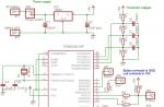
I decided to repeat this scheme, but to make a charger for charging two batteries at once. USB 2.0 output current is 500 mA. So you can safely connect two batteries. The finalized scheme looked like this.

I also wanted to be able to connect an external power supply with a voltage of 5 V.
The circuit contains only eight radio components.

From the tool you will need a minimum set of a radio amateur: a soldering iron, solder, flux, tester, tweezers, screwdrivers, a knife. Before soldering radio components, they must be checked for serviceability. For this we need a tester. Resistors are very easy to test. We measure their resistance and compare with the nominal value. There are many articles on the Internet about how to test a diode and an LED.
For the body I used a plastic case measuring 65 * 45 * 20 mm. The battery compartment was cut out of a Tetris children's toy.

I'll tell you more about the alteration of the battery compartment. The point is that initially
the pros and cons of the battery power terminals are set opposite. But I needed two insulated positive terminals in the upper part of the compartment, and one common negative terminal at the bottom. To do this, I moved the lower positive terminal up, and cut out the common negative terminal from tin, soldering the remaining springs.


As a flux when soldering springs, I used soldering acid in compliance with all safety regulations. Be sure to rinse the place of soldering in running water until traces of acid are completely removed. I soldered the wires from the terminals and passed them inside the case through the drilled holes.

The battery compartment was fixed on the cover of the case with three small screws.
I sawed out the board from the old modulator of the Dandy game console. Removed all unnecessary details and printed wiring tracks. Left only the power socket. I used thick copper wire as new tracks. I drilled holes in the bottom cover for ventilation.

The finished board sat tightly in the case, so I did not fix it.

After installing all the radio components in their places, we check the correct installation and clean the board from the flux.
Now let's unsolder the power cord and set the charging current for each battery.
As a power cord, I used a USB cord from an old computer mouse and a piece of power cord with a plug from Dandy.

The power cord must be given special attention. In no case should you confuse "+" and "-". I have a “+” power plug connected to the center pin with a black wire with a white stripe. And the "-" power goes through the black (without a strip) wire to the outer contact of the plug. On the USB cable, "+" goes to the red wire and "-" to the black one. We solder plus with plus and minus with minus. We carefully isolate the places of soldering. Next, we check the cord for a short circuit by connecting the tester in resistance measurement mode to the plug terminals. The tester should show infinite resistance. Everything must be carefully double-checked, no matter what burns the USB port. If everything is fine, we connect our cord to the USB port and check the voltage on the plug. The tester should show 5 volts.

The last step in the setup is setting the charging current. To do this, we break the circuit of the VD1 diode and the "+" battery. In the gap we connect the tester in the mode of measuring the current turned on to the limit of 200 mA. Plus the tester for the diode, and minus for the battery.

We insert the battery into place, observing the polarity, and apply power. At the same time, the LED should light up. It indicates that the battery is connected. Further, by changing the resistance R1, we set the required charge current. In our case, it is approximately 100 mA. With a decrease in the resistance of the resistor R1, the charging current increases, and with an increase it decreases.

We do the same for the second battery. After that, we twist our body and
the charger is ready to use.
Because different AA batteries have different
capacity, it will take different time to charge these batteries. Batteries
with a capacity of 1400 mAh with a voltage of 1.2 V will need to be charged using this
circuits for approximately 14 hours, and 700 mAh batteries will take only 7 hours.
I have batteries with a capacity of 2700 mAh. But I didn’t want to charge them for 27 hours from a USB port. Therefore, I made a power socket for an external power supply of 5 volts 1A, which I had lying idle.

Here are some more photos of the finished device.


Stickers were drawn using FrontDesigner 3.0. Then printed on a laser printer. I cut it out with scissors, pasted it with the front side on a thin adhesive tape 20 mm wide. Cut off excess tape. I used a glue stick as glue, after lubricating it with both the sticker and the place where it is glued. How reliable it is, I don't know yet.
Now the pros and cons of this scheme.
The advantage is that the circuit does not contain scarce and expensive parts and is assembled literally on the knee. It is also possible to power from the USB port, which is important for beginner radio amateurs. No need to puzzle over where to power the circuit. Despite the fact that the circuit is very simple, this charging method is used in many industrial chargers.
It is also possible, by slightly complicating the circuit, to implement switching of the charging current.

By selecting R1, R3 and R4, you can set the charging current for batteries of different capacities, thereby providing the recommended charging current for this battery, which is usually 0.1C (C-capacity of the battery).
Now the cons. The biggest one is the lack of stabilization of the charging current. That is
When the input voltage changes, the charging current will change. Also, if there is an error in the installation or a short circuit of the circuit, there is a high probability of burning the USB port.
If you use various devices that still use AA batteries, then you have to change them often, for example, in a metal detector or GPS-GLONAS eTrex travel navigator. But there is a solution to this problem - replacing conventional batteries with AA nickel batteries. This is where you need to charge your AA batteries.
For our purposes, almost any power supply designed for a voltage of 5-20 volts is suitable for us. Let's take the circuit of the simplest of them as a prototype of amateur radio development.

The circuit consists of the following radio components: resistance R1, two LEDs and a socket. LEDs are recommended to use different colors. In parallel to one of them, we solder the leads for connecting the battery in parallel. The glow of the LED in accordance with Ohm's law depends on the degree of discharge; when fully discharged, the LED will not light). During the charging process, the glow of the LED increases. The same glow of both LEDs indicates the end of the charging process. We select the value of resistance R1 in accordance with the operating current. For example, the operating current of the LED, which is 20 mA, and the voltage of the power supply
U bp. R 1 = U bp / I 1 = U bp / 0.02 = 50U bp
The resistor value is rounded up. Since the resistance R1 works for a long time, its power should be 1 watt. The parameters of our memory: Ubp = 25 V; R1 = 1.3 kOhm. Charging time 8 - 24 hours.
These designs allow you to charge portable Ni-Mn and Ni-Cd batteries with an operating voltage of 1.2-1.4 V from a USB port. Using the first circuit, you can charge one battery with a current of 100 mA, the second circuit allows you to charge two AA or AAA batteries.

The battery compartment was borrowed from an old children's toy. I'll tell you a little more about his alteration. The fact is that usually the pros and cons of the power terminals are installed oppositely. But we need to have two insulated positive terminals in the upper part, and one common negative terminal at the bottom. To do this, I moved the bottom one up, and cut out the common minus one from a beer can, soldering the springs. For soldering, I used soldering acid; at the end of soldering, be sure to rinse the surface well in running water.

Since different AA batteries have different capacities, it takes different times to charge these batteries. 1400 mAh batteries will take about 14 hours to charge, while 700 mAh batteries will take about 7 hours.
Today, there are a lot of different devices that run on batteries. And all the more annoying when, at the most inopportune moment, our device stops working, because the batteries are simply dead, and their charge is not enough for the normal functioning of the device.
Buying new batteries every time is quite expensive, but trying to make a home-made device for charging finger-type batteries with your own hands is quite worth it.Many craftsmen note that it is preferable to charge such batteries (AA or AAA) using direct current, because this mode is most beneficial in terms of safety for the batteries themselves. In general, the transferred charge strength from the network is about 1.2-1.6 of the capacity of the battery itself. For example, a nickel-cadmium battery with a capacity of 1A / h will be charged with a current of 1.6 A / h. At the same time, the lower the indicator of this power, the better for the charging process.
In the modern world, there are quite a few household appliances equipped with a special timer that counts down a certain period, then signaling its end. When making a do-it-yourself device for charging finger-type batteries, You can also use this technology, which will notify you when the battery charging process is complete.
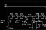
AA is a device that generates direct current, charging up to 3 Ah. In the manufacture, the most common, even the classic scheme, which you see below, was used. The basis, in this case, is the transistor VT1.

The voltage on this transistor is indicated by the red LED VD5, which acts as an indicator when the device is connected to the network. Resistor R1 sets a certain power of the currents passing through this LED, as a result of which the voltage in it fluctuates. The value of the collector current is formed by the resistance from R2 to R5, which are included in VT2 - the so-called "emitter circuit". At the same time, by changing the resistance values, you can control the degree of charging. R2 is permanently connected to VT1, setting the constant current with a minimum value of 70 mA. To increase the charge power, it is necessary to connect the remaining resistors, i.e. R3, R4 and R5.
Read also: Let's make an electric generator with our own hands
It is worth noting that The charger only functions when the batteries are connected..After turning on the device in the network, a certain voltage appears on the resistor R2, which is transmitted to the transistor VT2. Then, the current flows further, as a result of which the VD7 LED begins to burn intensively.
A story about a homemade device
USB charging
You can make a charger for nickel-cadmium batteries based on regular USB port. At the same time, they will be charged with a current with a capacity of approximately 100 mA. The scheme, in this case, will be as follows:

At the moment, there are quite a few different chargers sold in stores, but their cost can be quite high. Given that the main point of various homemade products is precisely to save money, then self-assembly is even more appropriate in this case.
This circuit can be improved by adding an additional circuit to charge a pair of AA batteries. Here's what happened in the end:

To make it more clear, here are the components that were used in the assembly process:

It is clear that we cannot do without elementary tools, so before starting the assembly, you need to make sure that you have everything you need:
- soldering iron;
- solder;
- flux;
- tester;
- tweezers;
- various screwdrivers and a knife.
Read also: Consider which voltage stabilizer to choose?
Interesting material about making your own hands, we recommend viewing
A tester is necessary in order to check the performance of our radio components. To do this, you need to compare their resistance, and then check with the nominal value.
For assembly, we also need a case and a battery compartment. The latter can be taken from the children's Tetris simulator, and the case can be made from a regular plastic case (6.5cm/4.5cm/2cm).
We fix the battery compartment on the case using screws. As a basis for the circuit, the board from the Dandy prefix, which needs to be cut out, is perfect. We remove all unnecessary components, leaving only the power socket. The next step is to solder all the parts based on our scheme.
The power cord for the device can be taken from a regular computer mouse cord with a USB input, as well as a part of the power cord with a plug. When soldering, polarity must be strictly observed, i.e. solder plus to plus, etc. We connect the cable to USB, checking the voltage that is supplied to the plug. The tester should show 5V.
For more than 4 years, faithfully serves me homemade charger for charging batteries "aa" and "aaa" (Ni-Mh, Ni-Ca) with a discharge function battery to a fixed voltage value (1 Volt). The battery discharge unit was created for the possibility of conducting CTC(Control-training cycle), to put it simply: to restore battery capacity battered by the wrong Chinese chargers with the formula for sequential charge of 2 or 4 batteries. As you know, this method of charging shortens the life of batteries if they are not restored in time. 


Charger Specifications:
- Number of independent charge channels: 4
- Number of independent discharge channels: 4
- Charge current: 250 (mA)
- Discharge current 140 (mA)
- Discharge cut-off voltage 1 (V)
- Indication: LED
The charger was not going to the exhibition, but what is called from improvised means, that is, the surrounding good was disposed of, which is a pity to throw out and there is no particular reason to store it.
From what you can make your own charging for "AA" and "AAA" batteries:
- Case from CD-Rom
- Power transformer from the radio (rewound)
- FETs from motherboards and HDD boards
- Other components were either bought or bitten :)
As already noted, charging consists of several nodes that can live completely autonomously from each other. That is, you can simultaneously work with 8 batteries: charge from 1 to 4 + discharge from 1 to 4. The photo shows that the battery cassettes are installed under the “AA” form factor in the common “finger-type batteries”, if you need to work with “AAA” “mini-finger-type batteries”, it is enough to put a small caliber nut under the negative terminal. If desired, you can duplicate the holders for the size "aaa". The presence of a battery in the holder is indicated by an LED (current flow is monitored).
Charge block

Charging is carried out with a stabilized current, each channel has its own current stabilizer. In order for the charge current to be unchanged when connecting both 1 and 2,3,4 batteries, a parametric voltage stabilizer is installed in front of the current stabilizers. Naturally, the efficiency of this stabilizer is not up to par and you will need to install all the transistors on the heat sink. Plan your case ventilation and heatsink dimensions in advance, taking into account that the temperature on the heatsink will be higher in a closed case than in a disassembled state. You can upgrade the circuit by introducing the ability to select the charge current. To do this, the circuit must be supplemented with one switch and one resistor for each channel, which will increase the base current of the transistor and, accordingly, increase the charge current passing through the transistor to the battery. In my case, the charge block is assembled by surface mounting.
battery discharge unit

The discharge unit is more complex and requires precision in the selection of components. It is based on a comparator such as lm393, lm339 or lp239, the function of which is to supply a “logical one” or “zero” signal to the gate of the field-effect transistor. When the field-effect transistor opens, it connects a load to the battery in the form of a resistor, the value of which determines the discharge current. When the voltage on the battery drops to the set cut-off threshold 1 (Volt). The comparator slams shut and sets its output to logic zero. The transistor comes out of saturation and disconnects the load from the battery. The comparator has a hysteresis, which causes the reconnection of the load not at a voltage of 1.01 (V) but at 1.1-1.15 (V). You can simulate the action of the comparator by downloading the . By selecting the values of the resistors, you can rebuild the device to the voltage you need. For example: by raising the shutdown threshold to 3 volts, you can make a discharge for li-on and Li-Po batteries.
You may have designed it to use the lm393 comparator in a DIP package. The comparators must be powered from a stabilized 5 volt source, its role is played by the TL-431 reinforced with a transistor.