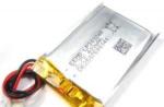
- ELM327 USB is latest version popular adapter for car diagnostics via OBDII protocol. Performs diagnostics for all OBDII protocols (including CAN). Works when connected to a PC via USB.
- U-480 OBDII CAN
- Autoscanner "SCANMATIC"
The main function of the diagnostic connector (in OBD II it is called the Diagnostic Link Connector - DLC) is to allow the diagnostic scanner to communicate with OBD II compatible control units. The DLC connector must comply with SAE J1962 standards. According to these standards, the DLC connector must occupy a certain central position in the car. It must be within 16 inches of the steering wheel. The manufacturer may place the DLC in one of eight locations designated by the EPA. Each pin of the connector has its own purpose. The function of many of the pins is left to the manufacturer's discretion, however these pins should not be used by OBD II compliant control units. Examples of systems using such connectors are SRS (Supplemental Restraint System) and ABS (Anti-Lock Wheel System).
From the point of view of an amateur, one standard connector located in a certain place makes the work of a car service easier and cheaper. A car service does not need to have 20 different connectors or diagnostic tools for 20 different vehicles. In addition, the standard saves time, since the specialist does not have to look for where the connector for connecting the device is located.
The diagnostic socket is shown in fig. 1. As you can see, it is grounded and connected to a power source (pins 4 and 5 are grounded, and pin 16 is power). This is done so that the scanner does not need to external source nutrition. If the scanner is not powered when you connect it, then you must first check pin 16 (power), as well as pins 4 and 5 (ground). Let's pay attention to alphanumeric characters: J1850, CAN and ISO 9141-2. These are protocol standards developed by SAE and ISO (International Organization for Standardization).
Manufacturers can choose from among these standards for diagnostic communication. Each standard corresponds to a specific contact. For example, communication with Ford vehicles is via pins 2 and 10, and with GM vehicles via pin 2. Most Asian and European brands use pin 7, and some also use pin 15. For understanding OBD II, it does not matter which protocol is under consideration. The messages exchanged between the diagnostic tool and the control unit are always the same. The only difference is the way messages are sent.
Standard communication protocols for diagnostics
So, the OBD II system recognizes several different protocols. Here we will discuss only three of them, which are used in cars manufactured in the USA. These are the J1850-VPW, J1850-PWM and ISO1941 protocols. All vehicle control units are connected to a cable called a diagnostic bus, resulting in a network. A diagnostic scanner can be connected to this bus. Such a scanner sends signals to the specific control unit with which it must communicate and receives response signals from this control unit. Messaging continues until the scanner terminates the communication session or is disconnected.
So, the scanner can ask the control unit about what errors it sees, and it answers this question. Such a simple exchange of messages must be based on some protocol. From an amateur's point of view, a protocol is a set of rules that must be followed in order for a message to be transmitted on a network.
Protocol classification
Association automotive engineers(SAE) has defined three distinct classes of protocols:
- Class A Protocol,
- class B protocol
- class C protocol
Class A Protocol - the slowest of the three; it can provide speeds of 10,000 bytes/s or 10 KB/s. The ISO9141 standard uses a Class A protocol.
Class B protocol 10 times faster; it supports messaging at 100Kb/s. The SAE J1850 standard is a class B protocol.
Class C protocol provides a speed of 1 MB / s. The most widely used Class C standard for vehicles is the CAN (Controller Area Network) protocol.
In the future, protocols with higher performance should appear - from 1 to 10 MB / s. As the need for more bandwidth and performance increases, class D may emerge. When working on a network with class C protocols (and in the future with class D protocols), we can use optical fiber. J1850 PWM protocol There are two types of J1850 protocol. The first of them is high-speed and provides a performance of 41.6 KB / s. This protocol is called PWM (Pulse Width Modulation - pulse width modulation). It is used in Ford brands, Jaguar and Mazda. For the first time this type of communication was used in Ford cars. In accordance with the PWM protocol, signals are transmitted over two wires connected to pins 2 and 10 of the diagnostic connector.
ISO9141 protocol
The third of the diagnostic protocols we are discussing is ISO9141. It was developed by ISO and is used in most European and Asian vehicles, as well as in some Chrysler cars. The ISO9141 protocol is not as complex as the J1850 standards. While the latter require the use of special communication microprocessors, ISO9141 requires conventional serial communication microprocessors, which are found on store shelves.
J1850 VPW protocol
Another variation of the J1850 diagnostic protocol is VPW (Variable Pulse Width). The VPW protocol supports 10.4Kb/s data transfer and is used in automobiles stamps General Motors (GM) and Chrysler. It is very similar to the protocol used in Ford vehicles, but is significantly slower. The VPW protocol provides for data transfer over a single wire connected to pin 2 of the diagnostic connector.
From an amateur's point of view,OBD II uses a standard diagnostic communication protocol , since the Environmental Protection Agency (EPA) required that auto repair shops receive a standard way to diagnose and repair cars without the expense of buying dealer equipment. These protocols will be described in more detail in subsequent publications.
Fault indication lamp
When the engine management system detects an exhaust gas problem, dashboard the word "Check Engine" lights up. This indicator is called the Malfunction Indication Light (MIL). The indicator usually displays the following inscriptions: Service Engine Soon (“Adjust the engine in soon”), Check Engine (“Check engine”) and Check (“Check”).
Purpose of the indicator consists in informing the driver that a problem has occurred during the operation of the engine management system. If the indicator lights up, do not panic! Nothing threatens your life, and the engine will not explode. You need to panic when the oil indicator or engine overheat warning lights up. The OBD II indicator only informs the driver of a problem in the engine management system that could lead to excess harmful emissions from exhaust pipe or contamination of the absorber.
From a layman's point of view, the MIL will illuminate when there is a problem with the engine control system, such as a faulty spark gap or dirty canister. In principle, it can be any malfunction that leads to an increased emission of harmful impurities into the atmosphere.
In order to check the operation of the OBD II MIL indicator , turn on the ignition (when all indicators on the instrument panel light up). At the same time, the MIL indicator lights up. The OBD II specification requires this indicator to be on for a while. Some manufacturers make the indicator stay on, while others make it turn off after a certain amount of time. When the engine is started and there are no faults in it, the “Check Engine” light should go out.

“Check Engine” light
does not necessarily light up at the first occurrence of a malfunction. The performance of this indicator depends on how serious malfunction. If it is considered serious and its elimination is urgent, the light comes on immediately. Such a malfunction belongs to the category of active (Active). If the troubleshooting can be delayed, the indicator is off and the fault is assigned a stored status (Stored). For such a fault to become active, it must occur within a few drive cycles. Typically, a drive cycle is a process in which cold engine starts and runs until it reaches normal operating temperature (the coolant temperature must be 122 degrees Fahrenheit).
During this process, all on-board test procedures relating to exhaust gases. Various cars have motors of different sizes, and therefore the drive cycles for them may vary slightly. As a rule, if the problem occurs within three drive cycles, then the lightcheck engineshould light up. If three drive cycles do not detect a malfunction, the light goes out. If the Check Engine light comes on and then goes off, don't worry. Error information is stored in memory and can be retrieved from there using a scanner. So, there are two fault statuses: stored and active. The saved status corresponds to the situation when a fault is detected, but Check indicator Engine does not light up - or lights up and then goes out. Active status means that the indicator is on when there is a fault.
DTC alpha pointer
As you can see, each symbol has its own purpose.
First charactercommonly referred to as the DTC alpha pointer. This symbol indicates in which part of the vehicle the fault is found. The choice of character (P, B, C or U) is determined by the diagnosed control unit. When a response is received from two blocks, the letter for the block with the higher priority is used.
Only four letters can be in the first position:
- P (engine and transmission);
- B (body);
- C (chassis);
- U (network communications).
In OBD II, a malfunction is described using diagnostic trouble codes (Diagnostic Trouble Code - DTC). DTCs according to the J2012 specification are a combination of one letter and four numbers. On fig. 3 shows what each character means. Rice. 3. Error code
Code types
Second character- the most controversial. It shows what the code defined. 0 (known as code P0). Base, open source malfunction, as defined by the Association of Automotive Engineers (SAE). 1 (or code P1). Fault code determined by the vehicle manufacturer. Most scanners cannot recognize the description or text of P1 codes. However, a scanner such as Hellion, for example, is able to recognize most of them. The SAE Association has defined the original list of diagnostic codes DTC errors. However, manufacturers began to talk about the fact that they already have their own systems, while no system is similar to another. The coding system for Mercedes vehicles is different from Honda systems, and they cannot use each other's codes. Therefore, the SAE Association promised to share standard codes(P0) and manufacturer codes (P1).
The system in which the problem was found
Third characterindicates the system where the fault is detected. Less is known about this symbol, but it is one of the most useful. Looking at it, we can immediately tell which system is faulty, without even looking at the error text. The third character helps to quickly identify the area where the problem occurred without knowing the exact description of the error code.
Fuel-air system.
- Fuel system(for example, injectors).
- Auxiliary system emission control, such as: Exhaust Gas Recirculation System (EGR) valve, Air Injection Reaction System (AIR), catalytic converter or ventilation system fuel tank(Evaporative Emission System - EVAP).
- Speed control system or idling, as well as the corresponding auxiliary systems.
- On-board computer system: Power-train Control Module (PCM) or Controller Area Network (CAN).
- Transmission or drive axle.
Fourth and fifth symbols must be considered together. They usually match old OBDI error codes. These codes usually consist of two digits. In the OBD II system, these two digits are also taken and inserted at the end of the error code - this makes it easier to distinguish between errors.
Now that we have seen how the standard set Diagnostic Trouble Codes (DTCs) as an exampleDTC P0301. Even without looking at the text of the error, you can understand what it is.
The letter P indicates that an error has occurred in the engine. The number 0 allows us to conclude that this is a basic error. This is followed by the number 3, referring to the ignition system. At the end we have a pair of numbers 01. In this case this pair of numbers tells us which cylinder is misfiring. Putting all this information together, we can say that there was an engine malfunction with misfires in the first cylinder. If a P0300 error code were issued, this would mean that there are misfires in several cylinders and the control system cannot determine which cylinders are faulty.
Self-diagnosis of malfunctions leading to increased toxicity of emissions.
The software that manages the self-diagnosis process is called by various names. Manufacturers ford cars and GM refer to him as the Diagnostic Executive, and Daimler Chrysler- Task Manager. It is a set of OBD II compliant programs that run in the Engine Control Module (PCM) and monitor everything that is happening around. The engine control unit is the real one workhorse! During every microsecond, it performs a huge amount of calculations and must determine when to open and close the injectors, when to energize the ignition coil, how much the ignition angle should be advanced, etc. During this process software OBD II verifies that all of the listed characteristics comply with the regulations.
This software:
- manages the state check bulbs engine;
- saves error codes;
- checks drive cycles that determine the generation of error codes;
- starts and executes component monitors;
- determines the priority of monitors;
- updates the readiness status of monitors;
- displays test results for monitors;
- does not allow conflicts between monitors.
According to OBD II, there are 2 types of monitors:
- continuous monitor (runs all the time while the corresponding condition is met);
- discrete monitor (triggered once during the trip).
Component Name Standardization
In any field, there are different names and slang words for the same concept. Take, for example, an error code. Some call it code, others call it a bug, others call it “the thing that broke”. The DTC designation is the error, code or “thing that broke”.
Before the advent of OBD II, each manufacturer came up with their own names for car components. It was very difficult to understand the terminology of the Association of Automotive Engineers (SAE) for someone who used the names adopted in Europe. Now, thanks to OBD II, standard component names must be used in all vehicles. Life has become much easier for those who repair cars and order spare parts. As always, when a government organization gets involved, abbreviations and jargon have become mandatory. The SAE Association has released a standardized list of terms for vehicle components related to OBD II. This standard is called J1930. There are millions of vehicles on the road today that use OBD II. Like it or not, OBD II affects everyone's life by making the air around us cleaner. The OBD II system allows the development of universal car repair techniques and really interesting technologies.
Therefore, we can safely say that OBD II is a bridge to the future of the automotive industry.
Subject:
Any modern car, even in minimum configuration, has its own and whole line specialized sensors that carefully monitor the state of the this moment the vehicle is located, how they work various devices. And in the event that all sorts of problems appear, all this is displayed as an error notification on the dashboard.
What to do?
After such a notification appears, the vehicle owner can send own car in a car service in order to conduct computer diagnostics there. In the service center they count with on-board computer error code, after which it will already determine for what specific reason he gave this error. However, few people know that there is actually an option independent holding computer diagnostics, and it is carried out using specialized diagnostic devices such as OBD-2.
What it is?
Today, such devices are installed in almost every modern car. OBD-2 connect directly to onboard system control the machine, and then interface with a range of components, including all kinds of smartphones, tablets, laptops and other gadgets using Bluetooth, USB or Wi-Fi connection.
At the same time, few people understand that in order to conduct a full-fledged electronic diagnostics car is not enough just to have such a device. You will also need to install a specialized program that can work with OBD-2 devices and will allow you to diagnose the electronics of your vehicle at any time. Such utilities today can be easily found on the Internet in the public domain, while the vast majority of manufacturers can also independently provide their own programs. However, as practice shows, all of them are often extremely inconvenient for the average user, as they are difficult to learn, confusing and lack support for the Russian language.
It is for this reason that quite often modern users begin to intensively search for a program that is most convenient for diagnosing equipment on a car. Today, you can find almost any utility that allows you to work with every modern operating system. And in order to make it as easy as possible to understand the countless offers, as well as to choose best option, you need to know the benefits and features of each individual utility.
iPhone Application

The undisputed leader among all currently existing programs is the OBD-2 iPhone Application utility, which, if necessary, can be used on devices such as iPad or iPhone. The program works exclusively with equipment such as ELM327 or directly OBD-2. The programs belong to the category of professional applications designed for the highest quality vehicle diagnostics, and therefore their functionality is similar to that present on standard computers.
What are the benefits?
If we talk about the advantages of these utilities, it is worth noting, first of all, mobility, since diagnostics can be carried out at any time and anywhere. In addition, this utility provides a thorough scan of the gearbox, and can also automatically check the airbag system, but the latter function may not be available depending on which model and brand of car you are using.
Special attention should be paid to the possibility of tracking in real time temperature indicators used cooling system, oil, as well as a number of other fluids, as this is one of the most important distinguishing features of this program for ELM327 and OBD-2. Programs allow you to turn your smartphone into a universal control center for your own car.
DashCommand

It is also a fairly powerful program that provides machine diagnostics via iPad or iPhone. It should be noted that OBD-2 diagnostics using this utility has no drawbacks compared to the previous utility, but it should be noted that such a program works only with ELM327 devices that support Wi-Fi connection.
What are the benefits?
The utility has a rather pleasant interface, and also allows you to completely clear the list of on-board computer errors. There is also support for monitoring fuel consumption in real time, and if necessary, it will even be possible to find out the cost of a trip if the cost of fuel for each liter is pre-entered into the program. One more interesting feature What makes these OBD-2 diagnostic programs different is that they display the load that the car experiences during braking, accelerating or cornering in much the same way as it is implemented in F1. Among other things, there is a utility that can be used in devices running the Android operating system.
Both programs can be easily downloaded and installed on the iPad or iPhone through the specialized iTunes application, which is available for any equipment from Apple. The only drawback of each of the aforementioned utilities is that they do not provide a version in Russian.
Torque

Today's leading utility that tracks OBD-2 errors through the Android operating system. By installing the program on your own smartphone or tablet that is controlled by this OS, you can completely independently diagnose your own car if it has an ELM327 device that supports transmission technology Bluetooth data. It is worth noting that in this utility there is almost complete functionality that a modern motorist may only need.
What are the benefits?
If we talk about the capabilities of this application, then they allow you not only to scan your own car, that is, to find out how many sensors and electronic systems are used in your vehicle and how they work. You can use your gadget as a tachometer or speedometer, or you can even make a device out of it that will show you the engine torque in real time. The excellent execution of the interface of this program, as well as the ability to choose from a huge number of indicators, will surely please any user who decides to use it.
This program allows not only to carefully read all OBD-2 codes from the on-board computer, but also to provide the user with brief information about an error by which it will be possible to easily find out the details of the problem via the Internet. Among other things, it also provides the function of completely clearing the log file. In addition, this program has a built-in GPS tracker function, which allows you to determine where and at what specific moment your car was in the process of activating this function, and if the car is currently in motion, then even information about the speed at which the car was moving along each individual section of the path.
With the help of this program, you will not only make your gadget really powerful and versatile, but also completely turn it into a kind of on-board computer. At the same time, a really significant advantage of this application is that it provides the ability to work in Russian, so that any user can diagnose his car and set it up as needed.
Utilities for Windows

It is worth immediately noting the fact that over time, decoding OBD-2 errors using programs that can be used exclusively based on the Windows operating system is constantly becoming less and less popular. The only advantage of such utilities over mobile programs is that both the device inside the car and the entire car system are extremely protected from the possibility of third-party connection, since the OBD-2 adapter interfaces with such utilities via USB.
Wi-Fi or Bluetooth programs, in principle, can be used in almost any gadget that uses the iOS or Android operating system and is at a distance of several meters from the computer. In other words, any person who is close to you and at the same time has the appropriate utility on his gadget can easily "get into" electronic system your car. A USB connection provides for direct contact of the device with a computer using a cable, as a result of which it is possible to get into the car's electronic system only if the operator is sitting in the driver's seat with a laptop in his hands.
ScanTool

To date, this program is probably the most common among all existing utilities that are designed to work in operating system Windows. It rightly deserves the title of the most common, as it has an intuitive interface, as well as enough a large number of various possibilities. The main among them should be called the presence of a huge database of errors, each of which contains detailed description. Among other things, do not forget that the utility provides a version in Russian, which greatly simplifies the decoding of errors and car diagnostics for most domestic users.
MyTester

This is an OBD-2 program (Bluetooth and Wi-Fi are also absent in it), which is ideal for modern owners of domestic cars, since it was originally written specifically for UAZ, VAZ and GAZ. Accordingly, it has an intuitive interface in Russian, and at the same time can work with ELM237. Among the distinguishing features of this utility, it is worth highlighting the fact that it scans the entire car in the shortest possible time, allows you to determine the temperature of the cooling systems, the consumption of the fuel mixture, and also deals with diagnostics. The unique function of this program is the diagnosis of such a parameter as atmospheric pollution by exhaust gases.
Knowing what devices exist and are currently used for diagnosing devices such as OBD-2 or ELM237, you can independently choose the program that is optimal for you, and then diagnose the car yourself at any time convenient for you. But at the same time, do not forget that before deleting the error log file from the on-board computer, it is imperative to make sure that these errors do not represent serious failures, since ignoring such notifications can lead to serious problems.
OBD-II is a standard for on-board diagnostics of a vehicle, developed in the 1990s in the United States and then spread to the whole world. automotive market. This standard provides for the implementation of full control of the condition of the engine, body parts and vehicle control systems.
OBD-II connector
Equipping a car with an on-board diagnostic system of the OBD-II standard provides for a special connector designed to connect diagnostic and control equipment to the car. The OBD-II connector is located inside the cab under the steering wheel and is a block with two rows of 8 pins. The diagnostic connector serves to power the equipment from battery car, grounding and information transmission channels.
The presence of a standard connector saves time for specialists service centers for car maintenance, which thereby eliminates the need to have a large number of separate connectors and devices for processing the signals coming from each connector.
Access to information and its processing
The OBD-II standard provides for the use of an error coding system. The error code consists of one letter followed by four digits, indicating malfunctions. various systems and vehicle components. Access to the information transmitted by the on-board diagnostics system provides valuable data necessary for faster and qualitative definition technical condition vehicle and troubleshooting.
In accordance with the ISO 15031 standard, the OBD-II data exchange system has various modes reading, processing and transmission of information. Car manufacturers decide which modes to use for specific model car. Also, manufacturers independently determine which of the diagnostic protocols to use when using the OBD-II system.
Exists special equipment to work with vehicle condition data according to the OBD-II standard. The devices differ in functionality and in general case are an adapter that connects to a car using an OBD-II connector and to a computer using a standard USB connector. The software is supplied with the equipment, thanks to which the reading and analysis of information is carried out.
All European and most Asian manufacturers used the ISO 9141 standard (K, L - line, - the topic was previously covered - connecting a conventional computer via an adapter K, L - lines for car diagnostics). General Motors used SAE J1850 VPW (Variable Pulse Width Modulation) and Fords used SAE J1850 PWM (Pulse Width Modulation). A little later came ISO 14230 (an improved version of ISO 9141, known as KWP2000). Europeans in 2001 adopted the EOBD (enhanced) extended OBD standard.
The main advantage is the presence of a high-speed CAN (Controller Area Network) bus. The name CAN bus came from computer terminology, since this standard was created around the 80s by BOSCH and INTEL as a computer network interface for real-time onboard multiprocessor systems. The CAN bus is a two-wire, serial, asynchronous peer-to-peer bus with common mode rejection. CAN is characterized high speed transmission (much greater than other protocols) and high noise immunity. For comparison, ISO 9141, ISO 14230, SAE J1850 VPW provide a data transfer rate of 10.4 Kbps, SAE J1850 PWM - 41.6 Kbps, ISO 15765 (CAN) - 250/500 kbit/s.
The compatibility of a particular car with the data exchange protocol - ISO9141-2 is easiest to determine by the OBD-2 diagnostic block (the presence of certain conclusions indicates a specific data exchange protocol). ISO9141-2 protocol (manufacturer Asia - Acura, Honda, Infinity, Lexus, Nissan, Toyota, etc., Europe - Audi, BMW, Mercedes, MINI, Porsche, some WV models, etc., early Chrysler models, Dodge, Eagle, Plymouth) is identified by the presence of pin 7 (K-line) in the diagnostic connector. Pins used are 4, 5, 7, 15 (may not be 15) and 16. ISO14230-4 KWP2000 (Daewoo, Hyundai, KIA, Subaru STi and some Mercedes models) is the same as ISO9141.
The standard OBD-II diagnostic connector looks like this.
Pin assignment (“pinout”) of the 16-pin OBD-II diagnostic connector (J1962 standard):
02 - J1850 Bus+
04 - Chassis Ground
05 - Signal Ground
06 - CAN High (ISO 15765)
07 - ISO 9141-2 K-Line
10 - J1850 Bus-
14 - CAN Low (ISO 15765)
15 - ISO 9141-2 L-Line
16 - Battery Power (battery voltage)
Omitted pins can be used by a specific manufacturer for their own needs.
Before connecting, in order not to be mistaken, it is necessary to call constant masses and + 12V with a tester. The main reason for the failure of the adapter is the incorrect connection of the mass, more precisely, the negative voltage on the K-line is critical (a short circuit to both ground and + 12V does not lead to failure of the K-line). The adapter has reverse polarity protection, but if negative wire connect to any actuating mechanism, and not to ground (for example, to a gas pump), but turn on the K-line to ground - in this case, we get the only dangerous variant of negative voltage on the K-line. If the power (ground) is connected correctly (for example, directly to the battery), it is no longer possible to burn the K-line in any way. In a car, there is often a similar K-line driver chip, but it is always turned on correctly, and you cannot burn the controller when you turn it on. The L line is less protected, and is a parallel channel on separate transistors (an erroneous connection to the power plus is unacceptable). If you do not plan to use a bidirectional L line, it is better to isolate the output (diagnosis of most cars, and also domestic ones, is performed only on the K line).
Diagnostics is performed with the ignition on.
It is advisable to follow the following connection sequences:
1. Connect the adapter to the PC.
2. Connect the adapter to the on-board controller in the following order: ground, +12 V, K line, L line (if necessary).
3. Turn on the PC.
4. Turn on the ignition or start the engine (in the latter version, a number of engine operation parameters are available).
5. Switch off in reverse order.
When using a conventional desktop computer, it is necessary to use sockets with grounding (in damp rooms, cases of breakdown of switching power supplies of the PC to the case are not uncommon, which is fraught not only with damage to equipment, including the on-board controller of the car, but is also associated with the risk of electric shock).