For the manufacture of power supplies for power amplifiers, as a rule, low-frequency 50-Hz transformers are used. They are reliable, do not create RF interference and are relatively easy to manufacture. But there are also disadvantages - dimensions and weight. Sometimes such shortcomings turn out to be decisive and other solutions have to be found. Partially, the issue of overall dimensions (more precisely, only height) is solved by using a torroidal transformer. But such a transformer, due to the complexity of manufacturing, costs a lot of money. And yet it still carries a lot of weight. The solution to this problem can be the use of a switching power supply.
But here are some peculiarities: difficulty in manufacturing, or alteration. To adapt a computer power supply for powering the PA, you need to solder half of the board and, most likely, rewind the secondary winding of the transformer. But the modern Chinese industry is churning out 12V Tashibra power supplies and the like, promising decent output power, 50W, 100W, 150W and more. At the same time, the cost of such power supplies is ridiculous.
In the figure, a couple of such blocks are above BUKO, below Ultralight, but in fact the same Tashibra. They have slight differences (perhaps they were made in different provinces of China): the secondary winding of Tashibra has 5 turns, and in BUKO - 8 turns. In addition, Ultralight has a slightly larger board, and there are places for installing additional parts. Despite this, they are redone identically. During the refinement process, you must be extremely careful, since there is a high voltage on the board, after the diode bridge it is 300 volts. In addition, if you accidentally short the output, the transistors will burn out.
Now about the scheme.

The scheme of power supplies from 50 to 150 watts is the same, the difference is only in the power of the parts used.
What needs to be improved?
1. It is necessary to solder the electrolytic capacitor after the diode bridge. The capacitance of the capacitor should be as large as possible. With this alteration, a 100 microfarad capacitor for a voltage of 400 volts was used.
2. Replace current feedback with voltage feedback. What is it for? In order for the power supply to start without load.
3. If necessary, rewind the transformer.
4. It will be necessary to rectify the output AC voltage with a diode bridge. For these purposes, you can use domestic diodes KD213, or imported, high-frequency. Better of course Schottky. It is also necessary to smooth out the ripple at the output with a capacitor.
Here is a diagram of the converted power supply.

The blue circle marks the current feedback coil. To turn it off, you must definitely unsolder one end so as not to create a short-circuited winding. After that, you can safely close the contact pads of the coil on the board. After that, it is necessary to organize voltage feedback. To do this, a piece of wire is taken from the twisted pair and 2 turns are wound on the power transformer. Then 3 turns are wound with the same wire on the T1 communication transformer. After that, a resistor of 2.4 - 2.7 Ohms, with a power of 5 - 10 watts, is soldered to the ends of this wire. A 12-volt light bulb is connected to the output of the converter, and a 220-volt, 150-watt light bulb is turned on in the break in the power wire. The first bulb is used as a load, and the second as a current limiter. We turn on the converter in the network. If the network light does not light up, then everything is fine with the converter and you can remove this light. We turn on the network again, already without it. If the 12-volt lamp on the load does not light up, then they did not guess with the direction of winding the communication coil on the communication transformer T1 and it will need to be wound in the other direction. After turning off the power, do not forget to discharge the network capacitor with a 1 kΩ resistor.
The power supply for ULF is usually bipolar, in this case it is necessary to obtain 2 voltages of 30 volts each. The secondary winding of the power transformer has 5 turns. With an output voltage of 12 volts, it turns out 2.4 volts per turn. To get 30 volts, you need to wind 30 volts / 2.4 volts = 12.5 turns. Therefore, it is necessary to wind 2 coils of 12.5 turns. To do this, it is necessary to unsolder the transformer from the board, temporarily wind two turns of voltage feedback and wind the secondary winding. After that, the calculated two secondary windings are wound with a simple stranded wire. First one coil is wound, then another. Two ends of different windings are connected - this will be a zero output.
If it is necessary to obtain a different voltage, more / fewer turns are wound.
The frequency of the power supply with a voltage coupling coil is about 30 kHz.
Then a diode bridge is assembled, electrolytes are soldered and ceramic capacitors are parallel to them to dampen high-frequency interference. Here are more options for connecting the secondary windings.
Making a good power supply for a power amplifier (VLF) or other electronic device is a very important task. The quality and stability of the entire device depends on what the power source will be.
In this publication I will talk about the manufacture of a simple transformer power supply for my homemade low-frequency power amplifier "Phoenix P-400".
Such an uncomplicated power supply can be used to power various low-frequency power amplifier circuits.
Foreword
For the future power supply unit (PSU) to the amplifier, I already had a toroidal core with a wound primary winding of ~ 220V, so the task of choosing a "pulse PSU or based on a network transformer" was not.
Switching power supplies have small dimensions and weight, high output power and high efficiency. The power supply based on the mains transformer is heavy, easy to manufacture and set up, and also does not have to deal with dangerous voltages when setting up the circuit, which is especially important for beginners like me.
toroidal transformer
Toroidal transformers, in comparison with transformers on armored cores made of Ш-shaped plates, have several advantages:
- smaller volume and weight;
- higher efficiency;
- best cooling for windings.
The primary winding already contained approximately 800 turns of 0.8 mm PELSHO wire, it was filled with paraffin and insulated with a layer of thin PTFE tape.
By measuring the approximate dimensions of the iron of the transformer, you can calculate its overall power, so you can figure out whether the core is suitable for obtaining the required power or not.

Rice. 1. Dimensions of the iron core for a toroidal transformer.
- Overall power (W) \u003d Window area (cm 2) * Cross-sectional area (cm 2)
- Window area = 3.14 * (d/2) 2
- Cross-sectional area \u003d h * ((D-d) / 2)
For example, let's calculate a transformer with iron dimensions: D=14cm, d=5cm, h=5cm.
- Window area \u003d 3.14 * (5cm / 2) * (5cm / 2) \u003d 19.625 cm 2
- Sectional area \u003d 5cm * ((14cm-5cm) / 2) \u003d 22.5 cm 2
- Overall power = 19.625 * 22.5 = 441 watts.
The overall power of the transformer I used turned out to be clearly less than I expected - somewhere around 250 watts.
Selection of voltages for secondary windings
Knowing the required voltage at the output of the rectifier after the electrolytic capacitors, it is possible to approximately calculate the required voltage at the output of the secondary winding of the transformer.
The numerical value of the direct voltage after the diode bridge and smoothing capacitors will increase by about 1.3..1.4 times, compared with the alternating voltage supplied to the input of such a rectifier.
In my case, to power the UMZCH, you need a bipolar constant voltage - 35 volts on each arm. Accordingly, an alternating voltage must be present on each secondary winding: 35 Volts / 1.4 \u003d ~ 25 Volts.
By the same principle, I made an approximate calculation of the voltage values \u200b\u200bfor other secondary windings of the transformer.
Calculation of the number of turns and winding
To power the remaining electronic components of the amplifier, it was decided to wind several separate secondary windings. A wooden shuttle was made for winding coils with copper enameled wire. It can also be made from fiberglass or plastic.
Rice. 2. Shuttle for winding a toroidal transformer.
The winding was carried out with copper enameled wire, which was available:
- for 4 UMZCH power windings - a wire with a diameter of 1.5 mm;
- for other windings - 0.6 mm.
The number of turns for the secondary windings I selected experimentally, since I did not know the exact number of turns in the primary winding.
The essence of the method:
- We wind 20 turns of any wire;
- We connect the primary winding of the transformer to the network ~ 220V and measure the voltage on the wound 20 turns;
- We divide the required voltage by that obtained from 20 turns - we find out how many times 20 turns are needed for winding.
For example: we need 25V, and out of 20 turns we get 5V, 25V / 5V = 5 - we need to wind 20 turns 5 times, that is, 100 turns.
The calculation of the length of the required wire was performed as follows: I wound 20 turns of wire, made a mark on it with a marker, unwound it and measured its length. I divided the required number of turns by 20, multiplied the resulting value by the length of 20 turns of wire - I got approximately the required length of wire for winding. By adding 1-2 meters of stock to the total length, you can wind the wire on the shuttle and safely cut it off.
For example: you need 100 turns of wire, the length of 20 wound turns turned out to be 1.3 meters, we find out how many times 1.3 meters need to be wound to get 100 turns - 100/20=5, we find out the total length of the wire (5 pieces of 1, 3m) - 1.3*5=6.5m. We add 1.5m for the stock and get the length - 8m.
For each subsequent winding, the measurement should be repeated, since with each new winding the length of wire required per turn will increase.
To wind each pair of windings of 25 volts, two wires were laid in parallel on the shuttle at once (for 2 windings). After winding, the end of the first winding is connected to the beginning of the second - we got two secondary windings for a bipolar rectifier with a connection in the middle.
After winding each of the pairs of secondary windings to power the UMZCH circuits, they were insulated with a thin fluoroplastic tape.
Thus, 6 secondary windings were wound: four for powering the UMZCH and two more for power supplies for the rest of the electronics.
Scheme of rectifiers and voltage stabilizers
Below is a schematic diagram of the power supply for my homemade power amplifier.

Rice. 2. Schematic diagram of the power supply for a homemade bass power amplifier.
To power the low-frequency power amplifier circuits, two bipolar rectifiers are used - A1.1 and A1.2. The remaining electronic components of the amplifier will be powered by voltage stabilizers A2.1 and A2.2.
Resistors R1 and R2 are needed to discharge electrolytic capacitors when the power lines are disconnected from the power amplifier circuits.
There are 4 amplification channels in my UMZCH, they can be turned on and off in pairs using switches that switch the power lines of the UMZCH scarf using electromagnetic relays.
Resistors R1 and R2 can be excluded from the circuit if the power supply is constantly connected to the UMZCH boards, in which case the electrolytic capacities will be discharged through the UMZCH circuit.
Diodes KD213 are designed for a maximum forward current of 10A, in my case this is enough. The diode bridge D5 is designed for a current of at least 2-3A, it was assembled from 4 diodes. C5 and C6 are capacitances, each of which consists of two 10,000 microfarad capacitors at 63V.

Rice. 3. Schematic diagrams of DC voltage stabilizers on L7805, L7812, LM317 microcircuits.
Deciphering the names on the diagram:
- STAB - voltage regulator without adjustment, current not more than 1A;
- STAB+REG - adjustable voltage regulator, current not more than 1A;
- STAB+POW - adjustable voltage stabilizer, current approximately 2-3A.
When using LM317, 7805 and 7812 microcircuits, the output voltage of the stabilizer can be calculated using a simplified formula:
Uout = Vxx * (1 + R2/R1)
Vxx for chips has the following meanings:
- LM317 - 1.25;
- 7805 - 5;
- 7812 - 12.
Calculation example for LM317: R1=240R, R2=1200R, Uout = 1.25*(1+1200/240) = 7.5V.
Design
Here's how it was planned to use the voltage from the power supply:
- +36V, -36V - power amplifiers on TDA7250
- 12V - electronic volume controls, stereo processors, output power indicators, thermal control circuits, fans, backlight;
- 5V - temperature indicators, microcontroller, digital control panel.
The voltage regulator chips and transistors were mounted on small heatsinks that I removed from non-working computer power supplies. The cases were attached to the radiators through insulating gaskets.
The printed circuit board was made of two parts, each of which contains a bipolar rectifier for the UMZCH circuit and the required set of voltage stabilizers.

Rice. 4. One half of the power supply board.

Rice. 5. The other half of the power supply board.
![]()
Rice. 6. Ready-made power supply components for a homemade power amplifier.
Later, during debugging, I came to the conclusion that it would be much more convenient to make voltage stabilizers on separate boards. Nevertheless, the "all on one board" option is also not bad and convenient in its own way.
Also, a rectifier for UMZCH (diagram in Figure 2) can be assembled by surface mounting, and stabilizer circuits (Figure 3) in the required quantity - on separate printed circuit boards.
The connection of the electronic components of the rectifier is shown in Figure 7.

Rice. 7. Connection diagram for assembling a bipolar rectifier -36V + 36V using surface mounting.
Connections must be made using thick insulated copper conductors.
The diode bridge with 1000pF capacitors can be placed separately on the heatsink. Mounting of powerful KD213 diodes (tablets) on one common radiator must be carried out through insulating thermal pads (thermoresin or mica), since one of the diode leads has contact with its metal lining!
For a filtering circuit (electrolytic capacitors of 10000 μF, resistors and ceramic capacitors of 0.1-0.33 μF), you can quickly assemble a small panel - a printed circuit board (Figure 8).

Rice. 8. An example of a panel with slots made of fiberglass for mounting rectifier smoothing filters.
To make such a panel, you need a rectangular piece of fiberglass. Using a homemade cutter (Figure 9), made from a hacksaw blade for metal, we cut the copper foil along the entire length, then we cut one of the resulting parts in half perpendicularly.

Rice. 9. Homemade cutter from a hacksaw blade, made on a grinder.
After that, we outline and drill holes for parts and fasteners, clean the copper surface with thin sandpaper and tin it with flux and solder. We solder the parts and connect to the circuit.
Conclusion
Here is such an uncomplicated power supply was made for a future homemade audio frequency power amplifier. It remains to supplement it with a soft start circuit and a standby mode.
UPD: Yuri Glushnev sent a printed circuit board for assembling two stabilizers with voltages + 22V and + 12V. It contains two STAB + POW circuits (Fig. 3) on LM317, 7812 microcircuits and TIP42 transistors.

Rice. 10. Printed circuit board of voltage stabilizers for + 22V and + 12V.
Download - (63 KB).
Another PCB designed for the STAB + REG adjustable voltage regulator circuit based on the LM317:

Rice. 11. Printed circuit board for an adjustable voltage regulator based on the LM317 chip.
It would seem that it could be easier to connect the amplifier to power supply and enjoy your favorite music?
However, if we recall that the amplifier essentially modulates the voltage of the power supply according to the law of the input signal, it becomes clear that the design and installation issues power supply should be approached very responsibly.
Otherwise, mistakes and miscalculations made at the same time can spoil (in terms of sound) any, even the most high-quality and expensive amplifier.
Stabilizer or filter?
Surprisingly, most power amplifiers are powered by simple circuits with a transformer, a rectifier, and a smoothing capacitor. Although most electronic devices today use stabilized power supplies. The reason for this is that it is cheaper and easier to design an amplifier that has a high ripple rejection ratio than it is to build a relatively powerful regulator. Today, the level of ripple suppression of a typical amplifier is about 60dB for a frequency of 100Hz, which practically corresponds to the parameters of a voltage regulator. The use of direct current sources, differential stages, separate filters in the power supply circuits of the stages and other circuitry techniques in the amplifying stages makes it possible to achieve even greater values.
Nutrition output stages most often made unstabilized. Due to the presence in them of 100% negative feedback, unity gain, the presence of LLCOS, the penetration of the background and ripple of the supply voltage to the output is prevented.
The output stage of the amplifier is essentially a voltage (power) regulator until it enters clipping (limiting) mode. Then the ripple of the supply voltage (frequency 100 Hz) modulates the output signal, which sounds just awful:

If for amplifiers with a unipolar supply only the upper half-wave of the signal is modulated, then for amplifiers with a bipolar supply, both half-waves of the signal are modulated. Most amplifiers have this effect at large signals (powers), but it is not reflected in the technical characteristics. In a well designed amplifier, clipping should not occur.
To test your amplifier (more precisely, the power supply of your amplifier), you can conduct an experiment. Apply a signal to the input of the amplifier with a frequency slightly higher than you can hear. In my case, 15 kHz is enough :(. Increase the amplitude of the input signal until the amplifier enters clipping. In this case, you will hear a hum (100 Hz) in the speakers. By its level, you can evaluate the quality of the power supply of the amplifier.
Warning! Be sure to turn off the tweeter of your speaker system before this experiment, otherwise it may fail.
A stabilized power supply avoids this effect and results in lower distortion during prolonged overloads. However, taking into account the instability of the mains voltage, the power loss on the stabilizer itself is approximately 20%.
Another way to reduce the clipping effect is to feed the stages through separate RC filters, which also reduces power somewhat.
In serial technology, this is rarely used, since in addition to reducing power, the cost of the product also increases. In addition, the use of a stabilizer in class AB amplifiers can lead to excitation of the amplifier due to the resonance of the feedback loops of the amplifier and regulator.
Power losses can be significantly reduced if modern switching power supplies are used. Nevertheless, other problems pop up here: low reliability (the number of elements in such a power supply is much larger), high cost (for single and small-scale production), high level of RF interference.
A typical power supply circuit for an amplifier with an output power of 50W is shown in the figure:

The output voltage due to smoothing capacitors is approximately 1.4 times greater than the output voltage of the transformer.
Peak Power
Despite these shortcomings, when the amplifier is powered from unstabilized source, you can get some bonus - short-term (peak) power is higher than the power of the power supply, due to the large capacity of the filter capacitors. Experience shows that a minimum of 2000µF is required for every 10W of output power. Due to this effect, you can save on the power transformer - you can use a less powerful and, accordingly, cheap transformer. Keep in mind that measurements on a stationary signal will not reveal this effect, it appears only with short-term peaks, that is, when listening to music.
A stabilized power supply does not give such an effect.
Parallel or series stabilizer?
There is an opinion that parallel regulators are better in audio devices, since the current loop is closed in a local load-stabilizer loop (power supply is excluded), as shown in the figure:

The same effect is obtained by installing a decoupling capacitor at the output. But in this case, the lower frequency of the amplified signal limits.

Protective resistors
Every radio amateur is probably familiar with the smell of a burnt resistor. It's the smell of burning varnish, epoxy and... money. Meanwhile, a cheap resistor can save your amp!
When the author first turns on the amplifier in the power circuits, instead of fuses, he installs low-resistance (47-100 Ohm) resistors, which are several times cheaper than fuses. This has repeatedly saved expensive amplifier elements from installation errors, incorrectly set quiescent current (the regulator was set to maximum instead of minimum), reversed power polarity, and so on.
The photo shows an amplifier where the installer mixed up TIP3055 transistors with TIP2955.

The transistors were not damaged in the end. Everything ended well, but not for the resistors, and the room had to be ventilated.
The key is voltage drop.
When designing printed circuit boards for power supplies and not only, one should not forget that copper is not a superconductor. This is especially important for "ground" (common) conductors. If they are thin and form closed circuits or long circuits, then due to the current flowing through them, a voltage drop occurs and the potential at different points turns out to be different.
To minimize the potential difference, it is customary to wire the common wire (ground) in the form of a star - when each consumer has its own conductor. The term "star" should not be taken literally. The photo shows an example of such a correct wiring of a common wire:

In tube amplifiers, the resistance of the anode load of the cascades is quite high, of the order of 4 kOhm and higher, and the currents are not very high, so the resistance of the conductors does not play a significant role. In transistor amplifiers, the resistance of the cascades is significantly lower (the load generally has a resistance of 4 ohms), and the currents are much higher than in tube amplifiers. Therefore, the influence of conductors here can be very significant.
The resistance of a track on a printed circuit board is six times higher than the resistance of a piece of copper wire of the same length. The diameter is taken 0.71mm, this is a typical wire that is used when mounting tube amplifiers.

0.036 Ohm as opposed to 0.0064 Ohm! Considering that the currents in the output stages of transistor amplifiers can be a thousand times higher than the current in a tube amplifier, we find that the voltage drop across the conductors can be 6000! times more. Perhaps this is one of the reasons why transistor amps sound worse than tube amps. This also explains why PCB-assembled tube amps often sound worse than surface-mounted prototypes.
Don't forget Ohm's law! Various techniques can be used to reduce the resistance of printed conductors. For example, cover the track with a thick layer of tin or solder a tinned thick wire along the track. The options are shown in the photo:

charge impulses
To prevent the penetration of the mains background into the amplifier, measures must be taken to prevent the penetration of charge pulses of the filter capacitors into the amplifier. To do this, the tracks from the rectifier must go directly to the filter capacitors. Powerful pulses of charging current circulate through them, so nothing else can be connected to them. the power supply circuits of the amplifier must be connected to the terminals of the filter capacitors.
The correct connection (mounting) of the power supply for an amplifier with unipolar power supply is shown in the figure:

Zoom on click
The figure shows a PCB variant:

Ripple
Most unregulated power supplies have only one smoothing capacitor after the rectifier (or several connected in parallel). To improve the quality of power, you can use a simple trick: split one container into two, and connect a small resistor of 0.2-1 ohm between them. At the same time, even two containers of a smaller denomination can be cheaper than one large one.

This gives a smoother output voltage ripple with less harmonics:

At high currents, the voltage drop across the resistor can become significant. To limit it to 0.7V, a powerful diode can be connected in parallel with the resistor. In this case, however, at the peaks of the signal, when the diode opens, the output voltage ripples will again become “hard”.
To be continued...
The article was prepared based on the materials of the journal "Practical Electronics Every Day"
Free translation: Editor-in-Chief of Radio Gazeta
Many people know how much I love to deal with different power supplies. This time I have a somewhat unusual power supply on my desk, at least I have not tested it yet. And by and large, I have never seen reviews of power supplies of this kind before, although the thing is interesting in its own way and I used to make similar power supplies myself.
I decided to order it out of pure curiosity, I decided that it might be useful. However, more details in the review.
In general, it is probably worth starting with a small lyrical introduction. Many years ago, I was quite fond of audio equipment, I went through both completely home-made options and “hybrids”, where PAs with a power of up to 100 watts from the Young Technician store were used, and the semi-disassembled Radio Engineering UCU 010, 101 and Odyssey 010, then there was the Phoenix 200U 010S .
I even tried to assemble Sukhov’s UMZCH, but something didn’t work then, I don’t even remember what exactly. 
The acoustics were also different, both home-made and ready-made, for example, Romantika 50ac-105, Cleaver 150ac-009. 
But most of all I remember Amfiton 25AC 027, although I had them somewhat modified. Along the way, to small changes in the circuit and design, I replaced the native speakers 50 HDN with 75 HDN.
This and the previous photos are not mine, since my equipment was sold a long time ago, and then I switched to Sven IHOO 5.1, and then generally began to listen only to small computer speakers. Yes, this is a regression. 
But then something began to wander in my head thoughts, to do something, for example, a power amplifier, maybe just like that, maybe do everything differently. But in the end I decided to order a power supply. Of course, I can do it myself, moreover, in one of the reviews I not only did it, but also posted detailed instructions, but I'll come back to this, but for now I'll move on to the review.
I'll start with a list of declared technical characteristics:
Supply voltage - 200-240 Volts
Output power - 500 watts
Output voltages:
Main - ±35 Volts
Auxiliary 1 - ± 15 Volt 1 Amp
Auxiliary 2 - 12 Volt 0.5 Ampere, galvanically isolated from the rest.
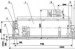
Dimensions - 133 x 100 x 42 mm
Channels ± 15 and 12 Volts are stabilized, the main voltage ± 35 Volts is not stabilized. Here I will express my opinion.
I am often asked which power supply to buy for one or another amplifier. To which I usually answer - it's easier to assemble it yourself based on well-known IR2153 drivers and their analogues. The first question that follows after this is that they do not have voltage stabilization.
Yes, personally, in my opinion, UMZCH supply voltage stabilization is not only unnecessary, but sometimes harmful. The fact is that a stabilized PSU is usually noisier at HF and, in addition, there may be problems with stabilization circuits, because the power amplifier consumes energy not evenly, but in bursts. We listen to music, not just one frequency.
A PSU without stabilization usually has a slightly higher efficiency, since the transformer always operates in the optimal mode, has no feedback and therefore looks more like a conventional transformer, but with lower winding resistance.
Here we have an example of a PSU for power amplifiers.
The packaging is soft, but wrapped in such a way that it is unlikely to be damaged during the delivery process, although the confrontation between the mail and sellers will probably be eternal. 
Outwardly it looks beautiful, especially and you will not find fault. 

The size is relatively compact, especially when compared with a conventional transformer of the same power. 
More clear sizes are on the product page in the store. 
1. A connector is installed at the input of the power supply, which turned out to be quite convenient.
2. There is a fuse and a full-fledged input filter. But they forgot about the thermistor, which protects both the network and the diode bridge with capacitors from current surges, this is bad. Also in the area of the input filter there are contact pads that must be closed to transfer the PSU to a voltage of 110-115 Volts. Before turning on for the first time, it is better to check if the sites are closed if you have 220-230 in your network.
3. Diode bridge KBU810, everything would be fine, but it is without a radiator, and at 500 watts it is already desirable.
4. The input filter capacitors have a declared capacitance of 470 uF, the real one is about 460 uF. Since they are connected in series, the total capacitance of the input filter is 230uF, which is not enough for an output power of 500 watts. By the way, the board involves the installation of one capacitor. But in any case, I would not advise raising the container without installing a thermistor. Moreover, to the right of the fuse there is even a place for the thermistor, you just need to solder it and cut the track under it. 
The inverter uses IRF740 transistors, although they are far from new transistors, but I also used them widely in similar applications before. As an alternative, IRF830.
Transistors are installed on separate radiators, this is partly done for a reason. The heatsinks are connected to the body of the transistor, and not only at the place of fastening of the transistor itself, but also the mounting leads of the heatsink are connected on the board itself. In my opinion, a bad decision, since there will be excess radiation on the air at the conversion frequency, at least the lower transistor of the inverter (in the photo it is distant) I would untie from the radiator, and the radiator from the circuit.
An unknown module controls the transistors, but judging by the presence of a power resistor, and just my experience, I think that I won’t be much mistaken if I say that there is a banal IR2153 inside. though why to make such a module remains a mystery to me. 
The inverter is assembled according to a half-bridge circuit, but not the connection point of the filtering electrolytic capacitors is used as the midpoint, but two film capacitors with a capacity of 1 μF (in the photo two are parallel to the transformer), and the primary winding is connected through a third capacitor, also with a capacity of 1 μF (perpendicular to the transformer in the photo) .
The solution is well-known and convenient in its own way, since it makes it very easy not only to increase the capacitance of the input filter capacitor, but also to use one for 400 volts, which can be useful when upgrading. 
The size of the transformer is very modest for the declared power of 500 watts. Of course, I will test it under load, but I can already say that in my opinion its real continuous power is more than 300-350 watts.
On the store page, in the list of key features, it was indicated -
3. Transformers 0.1mm * 100 multi-strand oxygen-free enameled wire, heat is very low, efficiency is more than 90%.What does it mean in translation - the winding of 100 pieces of oxygen-free wires with a diameter of 0.1 mm is used in the transformer, heating is reduced and the efficiency is above 90%.
Well, I'll check the efficiency later, but about the fact that the winding is multi-wire, it's a fact. Of course, I didn’t count them, but the harness is pretty good and this winding option really has a positive effect on the quality of the transformer in particular and the entire PSU as a whole.

They didn’t forget about the capacitor connecting the “hot” and “cold” side of the PSU, and they put it in the correct (Y1) type. 
In the output rectifier of the main channels, diode assemblies MUR1620CTR and MUR1620CT (16 Ampere 200 Volts) were used, and the manufacturer did not begin to collective farm "hybrid" options, but installed, as expected, two complementary assemblies, one with a common cathode, and the other with a common anode. Both assemblies are mounted on separate heatsinks and, like the transistors, they are not isolated from the components. But in this case, the problem can only be in terms of electrical safety, although if the case is closed, then there is nothing wrong with that.
The output filter uses a pair of 1000uF x 50 Volt capacitors, which in my opinion is not enough. 
In addition, a choke is installed between the capacitors to reduce ripples, and the capacitors after it are additionally shunted with a ceramic 100 nF.
In general, on the product page it was written -
1. All high-frequency low-impedance electrolytic capacitors specifications, low ripple.In translation - all capacitors have a low impedance to reduce ripple. In general, this is how it is, Cheng-X is used, but this is essentially just a slightly improved version of ordinary Chinese capacitors and I would rather put my favorite Samwha RD or Capxon KF.
There are no discharge resistors in parallel with the capacitors, although there is room for them on the board, so you can expect “surprises” since the charge lasts for quite a long time. 
Additional power channels are connected to their transformer windings, and the 12 Volt channel is galvanically isolated from the rest.
Each channel has independent voltage regulation, noise reduction chokes and ceramic output capacitors. But you probably noticed that there are five diodes in the rectifier. The 12 Volt channel is powered by a half-wave rectifier. 
At the exit, as well as at the entrance, there are terminal blocks, and of very good quality and design. 
On the product page there is a photo above, where you can see everything at once. Later I noticed that in the store there are mounting racks in all the photos, they were not in my kit :( 
The printed circuit board is double-sided, the quality is very high, fiberglass is used, and not the usual getinaks. A protective slot is made in one of the narrow places.
A couple of resistors were also found underneath, I assume that this is a primitive overload protection circuit, which is sometimes added to drivers on the IR2153. But honestly, I wouldn't count on it. 
Also at the bottom of the printed circuit board there is a marking of the outputs and output voltage options for which these boards are made. A little intrigued by two things - two identical options ± 70 Volts and a custom option. 
Before moving on to the tests, I’ll tell you a little about my version of such a PSU.
About three and a half years ago, I laid out an adjustable power supply unit, where a power supply unit assembled in approximately the same way was used. 
When assembled, it also looked pretty similar, sorry for the poor photo quality. 
If we remove everything “superfluous” from my version, for example, a fan speed control unit depending on temperature, as well as a powerful transistor driver and an additional power supply circuit from the inverter output, then we will get the circuit of the monitored PSU.
In fact, this is the same PSU, only there are more output voltages. In general, the circuitry of this PSU is quite simple, only a banal oscillator is simpler. 
In addition, the observed PSU is equipped with a primitive output power limiting circuit, I suspect that it is implemented as shown in the highlighted section of the circuit. 
But let's look at what this circuit and its implementation in the monitored power supply are capable of.
It should be noted here that since there is no stabilization of the main voltage, it directly depends on the voltage in the network.
With an input voltage of 223 Volts, the output is 35.2 in idle mode. Consumption is 3.3 watts. 
In this case, there is a noticeable heating of the power supply resistor of the transistor driver. Its nominal value is 150 kOhm, which at 300 volts gives a power dissipation of the order of 0.6 watts. This resistor heats up regardless of the load on the power supply.
A slight heating of the transformer is also noticeable, the photo was taken about 15 minutes after switching on. 
For the load test, a design was assembled, consisting of two electronic loads, an oscilloscope and a multimeter.
The multimeter measured one power channel, the second channel was controlled by a voltmeter of the electronic load, which was connected with short wires. 
I will not bore the reader with a large enumeration of tests, so I will immediately move on to the oscillograms.
1, 2. Different PSU output points to diode assemblies, and with different sweep times. The frequency of the inverter is 70 kHz.
3, 4. Ripple before and after the 12 Volt channel inductor. After Krenka, everything is generally smooth, but there is a problem, the voltage at this point is only about 14.5 Volts without loading the main channels and 13.6-13.8 with a load, which is not enough for a 12 Volt stabilizer. 
The load tests went like this:
First, I loaded one channel by 50%, then the second by 50%, then the load of the first was raised to 100%, and then the second. As a result, four load modes were obtained - 25-50-75-100%.
First, that at the HF output, in my opinion, it’s very good, the ripples are minimal, and when installing an additional choke, they can generally be reduced to almost zero. 
But at a frequency of 100 Hz, everything is rather sad, the input capacitance is too small, not enough.
The full swing of the ripple at 500 watts of output power is about 4 volts. 
Load tests. Since the voltage sagged under load, I increased the load current as it did so that the output power approximately corresponded to the 125-250-375-500 watt range.
1. The first channel - 0 Watts, 42.4 Volts, the second channel - 126 Watts, 33.75 Volts
2. The first channel - 125.6 watts, 32.21 volts, the second channel - 130 watts, 32.32 volts.
3. The first channel - 247.8 Watts, 29.86 Volts, the second channel - 127 Watts, 30.64 Volts.
4. The first channel - 236 watts, 29.44 volts, the second channel - 240 watts, 29.58 volts.
You probably noticed that in the first test, the voltage of an unloaded channel is more than 40 volts. This is due to voltage surges, and since there is no load at all, the voltage rises smoothly, even a small load returns the voltage to normal. 
Consumption was measured at the same time, but since there is a relatively large error in measuring the output power, I will also give the calculated efficiency values approximately.
1. 25% load, 89.3% efficiency
2. 50% load, efficiency 91.6%
3. 75% load, 90% efficiency
4. 476 watts, about 95% load, 88% efficiency
5, 6. Just for the sake of curiosity, I measured the power factor at 50 and 100% power.
In general, the results are approximately similar to the declared 90% 
The tests showed a pretty good performance of the power supply and everything would be great if it were not for the usual “fly in the ointment” in the form of heating. At the very beginning, I estimated the PSU power at about 300-350 watts.
In the course of the usual test with gradual warming up and intervals of 20 minutes, I found out that at a power of 250 watts, the BP behaves just fine, the heating of the components is something like this:
Diode bridge - 71
Transistors - 66
Transformer (magnetic circuit) - 72
Output diodes - 75
But when I raised the power to 75% (375 watts), then after 10 minutes the picture was completely bad
Diode bridge - 87
Transistors - 100
Transformer (magnetic circuit) - 78
Output diodes - 102
(more loaded channel)
Trying to deal with the problem, I found out that there was a strong overheating of the transformer windings, as a result of which the magnetic circuit warmed up, its saturation induction decreased and it began to enter saturation, as a result, the heating of the transistors sharply increased (later I recorded the temperature up to 108 degrees), then I stopped test. At the same time, cold tests with a power of 500 watts were normal.
Below are a couple of thermal photos, the first at a load power of 25%, the second at 75%, respectively, after half an hour (20 + 10 minutes). The temperature of the windings reached 146 degrees and there was a noticeable smell of overheated varnish. 
In general, now I will sum up some results, partly disappointing.
The overall workmanship is very good, but there are some design nuances, such as the installation of transistors without insulation from heatsinks. Pleased with a large number of output voltages, for example, 35 volts for powering a power amplifier, 15 for a pre-amplifier and independent 12 volts for any service devices.
There are circuit flaws, for example, the absence of a thermistor at the input and a small capacitance of the input capacitors.
In the specifications, it was stated that additional 15 Volt channels can deliver a current of up to 1 Ampere, in reality, I would not expect more than 0.5 Ampere without additional cooling of the stabilizers. The 12 Volt channel most likely will not give out more than 200-300mA at all.
But all these problems are either not critical or easily solved. The biggest problem is heating. The PSU can deliver up to 250-300 watts for a long time, 500 watts only for a relatively short time, or active cooling will have to be added.
Along the way, I had a small question for the respected public. There are thoughts to make your own amplifier, according to the reviews. But which one would be more interesting, a power amplifier, preliminary, if UM, then at what power, etc. Personally, I don’t really need it, but there is a mood to dig deeper. The monitored BP has little to do with this :)
That's all for me, I hope that the information was useful and, as usual, I'm waiting for questions in the comments.
The product was provided for writing a review by the store. The review is published in accordance with clause 18 of the Site Rules.
I plan to buy +38 Add to favorites Liked the review +115 +179I also made an inverter so that it could be powered from 12 V, that is, an automotive version. After everything was done in terms of the ULF, the question was raised: how to feed it now? Even for the same tests, or just to listen? I thought it would cost all the ATX PSU, but when you try to “heap”, the PSU reliably goes into defense, but somehow you don’t really want to redo it ... And then the idea dawned on me to make my own, without any “bells and whistles” of the PSU (except for protection, of course). I started with the search for schemes, looked closely at the schemes that were relatively simple for me. Finally settled on this one:
It holds the load perfectly, but replacing some parts with more powerful ones will allow you to squeeze 400 watts or more out of it. The IR2153 microcircuit is a self-clocked driver, which was developed specifically for operation in energy-saving lamp ballasts. It has very low current consumption and can be powered through a limiting resistor.
Device Assembly
Let's start with etching the board (etching, stripping, drilling). Archive with PP.


First I bought some missing parts (transistors, irka, and powerful resistors).

By the way, the surge protector completely removed from the PSU from the disc player:


Now the most interesting thing in the SMPS is the transformer, although there is nothing complicated here, you just need to understand how to wind it correctly, and that's all. First you need to know what and how much to wind, there are many programs for this, but the most common and popular among radio amateurs is - Excellent IT. In it, we will calculate our transformer.

As you can see, we got 49 turns of the primary winding, and two windings of 6 turns each (secondary). Let's swing!
Transformer manufacturing
Since we have a ring, most likely its edges will be at an angle of 90 degrees, and if the wire is wound directly onto the ring, the varnish insulation may be damaged, and as a result, an interturn short circuit and the like. In order to exclude this moment, the edges can be carefully cut with a file, or wrapped with cotton tape. After that, you can wind the primary.

After it is wound, we wrap the ring with the primary winding with electrical tape again.

Then we wind the secondary winding from above, though it’s a little more complicated here.

As you can see in the program, the secondary winding has 6 + 6 turns, and 6 cores. That is, we need to wind two windings of 6 turns with 6 cores of wire 0.63 (you can choose by first writing in the field with the desired wire diameter). Or even simpler, you need to wind 1 winding, 6 turns with 6 cores, and then the same one again. To make this process easier, it is possible, and even necessary, to wind in two tires (bus-6 cores of one winding), so we avoid voltage distortion (although it can be, but small, and often not critical).

Optionally, the secondary winding can be insulated, but not necessarily. Now after that we solder the transformer with the primary winding to the board, the secondary to the rectifier, and I used a unipolar rectifier with a midpoint.

Of course, the consumption of copper is greater, but there is less loss (respectively, less heating), and you can use only one diode assembly with an ATX power supply unit that has expired, or is simply inoperative. The first power-up must be carried out with the light bulb turned on in the mains supply, in my case I just pulled out the fuse, and the plug from the lamp is perfectly inserted into its socket.


If the lamp flashed and went out, this is normal, since the mains capacitor was charged, but I didn’t have this phenomenon, either because of the thermistor, or because I temporarily set the capacitor to only 82 uF, or maybe it provides everything smooth start. As a result, if there are no problems, you can turn on the SMPS network. At a load of 5-10 A, below 12 V I didn’t sink, what is needed to power auto amplifiers!
- If the power is only about 200 W, then the resistor that sets the protection threshold R10 should be 0.33 Ohm 5 W. If it is in a break, or burns out, all transistors will burn out, as well as the microcircuit.
- The network capacitor is selected from the calculation: 1-1.5 microfarads per 1 W of unit power.
- In this circuit, the conversion frequency is approximately 63 kHz, and during operation, it is probably better for the 2000NM brand ring to reduce the frequency to 40-50 kHz, since the limiting frequency at which the ring operates without heating is 70-75 kHz. You should not chase a high frequency, for this circuit, and a 2000NM ring, it will be optimally 40-50 kHz. Too high a frequency will cause switching losses on the transistors and significant losses on the transformer, which will cause it to heat up significantly.
- If your transformer and keys heat up at idle with proper assembly, try reducing the capacitance of the snubber capacitor C10 from 1 nF to 100-220 pF. The keys must be isolated from the radiator. Instead of R1, you can use a thermistor with an ATX power supply.
Here are the final photos of the power supply project:


Discuss the article POWERFUL PULSE NETWORK BIPOLAR POWER SUPPLY