At the same time, for most gearboxes, such a thing as the main gear of a car is relevant. Next, we will talk about what the main gear is and what it is for.
Read in this article
What is the main gear for and what is it
As you know, today the following types of gearboxes are installed on cars:
- (transmission selection is carried out manually);
- (provides automatic selection of the gear corresponding to the current traffic conditions);
- (provides a smooth change in gear ratio.);
- (mechanical box gears, clutch disengagement and gearshift functions are automated).
The main task of the gearbox is the transmission and change of torque from the engine to the drive wheels with the possibility of changing gear ratios. At the output of the box, the torque is small, and the rotation speed of the output shaft is high.
To increase the torque and reduce the speed of rotation, the main gear of the car, which has a certain gear ratio, is used. The gear ratio of the main gear depends on the type, purpose of the car and engine speed. Usually the gear ratios of the main gears cars are in the range of 3.5-5.5, cargo 6.5-9.
Final drive in a car

The main gear of the car is a permanent gear gear reducer, consisting of driving and driven gears of different diameters. The location of the main gear of the car depends on design features the vehicle itself:
- cars with front-wheel drive - the main gear is installed with a differential in a single gearbox housing;
- cars with rear wheel drive- the main gear is installed as a separate unit in the drive axle housing;
- cars with all-wheel drive- the main gear can be installed both in the gearbox and separately in the drive axle. It all depends on the location ICE car(transverse or longitudinal).
There is also a classification of main gears according to the number of gear stages. Depending on the purpose and layout, both single and double main gears are used on cars.
A single main gear consists of one pair of gears leading and driven. Used on cars and trucks. The double final drive consists of two pairs of gears and is mainly used on trucks of medium and heavy duty to increase torque or to increase ground clearance by off-road vehicles. The transmission efficiency is 0.93-0.96.
Double transmissions can be divided into two types:
- double central final drive - both stages are located in one crankcase in the center of the drive axle;
- double spaced main gear - the bevel pair is located in the center of the drive axle, and the cylindrical pair is in the wheel gears.
When the main gear is divided into two parts, the loads on and parts are reduced. The dimensions of the crankcase of the middle part of the drive axle are also reduced, as a result, the ground clearance and cross-country ability of the vehicle increase. However, the spaced transmission is more expensive and difficult to manufacture, has a high metal content, and is more difficult to maintain.
Types of main gear by type of gear connection

If we divide the types of main gears, then we can distinguish:
- cylindrical;
- conical;
- worm;
- hypoid;
Cylindrical main gear is used on passenger front-wheel drive vehicles with a transverse engine and gearbox. Its gear ratio is in the range of 3.5-4.2.
The gears of the cylindrical final drive can be spur, helical and herringbone. Cylindrical gear has high efficiency(not less than 0.98) but it reduces ground clearance and is quite noisy.
- The bevel final drive is used on rear-wheel drive light and medium duty vehicles with a longitudinal ICE location, Where dimensions does not matter.
The axes of the gears and the wheels of such a transmission intersect. These gears use straight, oblique or curved (spiral) teeth. Noise reduction is achieved by using an oblique or spiral tooth. The efficiency of the main gear with a spiral tooth reaches 0.97-0.98.
- The worm main gear can be either with the lower or with the upper location of the worm. The gear ratio of such a final drive is in the range from 4 to 5.
Compared to other types of gears, the worm gear is more compact and less noisy, but has a low efficiency of 0.9 - 0.92. Currently, it is rarely used due to the complexity of manufacturing and the high cost of materials.
- The hypoid main gear is one of the popular types gear connection. This transmission is a kind of compromise between bevel and worm final drives.
The transmission is used on rear-wheel drive cars and trucks. The axes of the gears and the wheels of the hypoid gear do not intersect, but cross. The gear itself can be either with a lower or with an upper offset.
The bottom offset main gear allows the cardan gear to be positioned lower. Consequently, the center of gravity of the car is also shifted, increasing its stability when driving.
The hypoid gear, compared to the bevel gear, has greater smoothness, noiselessness, and smaller dimensions. It is used on passenger cars with a gear ratio of 3.5-4.5, and on trucks instead of a double final drive with a gear ratio of 5-7. In this case, the efficiency of the hypoid gear is 0.96-0.97.
With all its advantages, the hypoid gear has one drawback - the jamming threshold during the reverse motion of the car (exceeding the calculated speed). For this reason, the driver needs to be especially careful when choosing the reverse speed.
Summing up
So, having figured out what the main gear of the car is for and what types of main gears are used in the transmission, its purpose becomes clear. As you can see, the device and the principle of operation of this node are relatively simple.
At the same time, it is important to understand that given element transmission has a significant impact on fuel consumption, dynamics and whole line other characteristics and indicators of the car.
Read also
Gearbox differential: what is it, differential device, types of differentials. How does a gearbox differential work in a car transmission.

The largest gear ratio that can be obtained using a single gear train, is limited by the diameter of the driven gear. In order for the gear ratio to be greater than 6.7, apply main double gears. They allow provide almost any gear ratio and create through gears provided by the transmission design. The main double gears are installed on heavy-duty vehicles where the overall gear ratio of the transmission must be significant as torques are transmitted large size. In the main double gear, the torque is increased sequentially by two pairs of gears, one of which is bevel and the other is cylindrical. The total double gear ratio is equal to the product of the gear ratios of the component pairs.
The central main double gear of ZIL vehicles consists of the following elements:
Leading bevel gear, made as one piece with a shaft that receives torque from the driveline;
driven bevel gear with spiral teeth, which is attached to the intermediate shaft flange with rivets;
an intermediate shaft with a helical spur gear (drive), made as one piece with the shaft;
driven cylindrical helical gear, which is bolted to the body of the differential box, consisting of left and right cups.
The shaft of the driving bevel gear is supported by roller bearings located in a cup bolted to the final drive housing. The countershaft of the driving spur gear is supported by tapered roller bearings, which are located in the side covers of the final drive housing. Adjusting shims are provided for adjusting the bearings. The differential box rotates on two capped tapered roller bearings. These roller bearings are adjusted with special nuts.
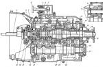
The drive axle of the ZIL car and the main double gears of the ZIL:
1 - flange; 2 - cuff; 3, 15, 18 and 32 - covers; 4 - washer; 5 - sealing gasket; 6, 9, 14 and 24 and 31 - roller bearings; 7 - glass; 8 - adjusting washers; 10 and 13 - shims; 11 - bevel drive gear; 12 - bevel driven gear; 16 - cylindrical drive gear; 17- main gear housing; 19 and 29 - support washers; 20-right differential cup; 21 - cylindrical driven gear; 22 - semi-axial gear; 23 - left differential cup; 25 - adjusting nut; 26 - axle shaft; 27 - crankcase of the bridge; 28 - satellite; 30 - cross; 33 - spacer sleeve.
Dual split final drive is applied on heavy duty trucks when gear ratio io ≥ 11 and on multi-purpose vehicles to obtain the required ground clearance.
Advantages transfers:
The transmission ratio can reach 20...30;
Smaller dimensions and weight of the cross-axle differential and the diameter of the axle shafts;
compact central part drive axle, which is important for obtaining low level floor and center of mass of the car, as well as to ensure the required ground clearance;
Possibility of adjusting the gear ratio of the main gear without changing the central part of the drive axle;
Onboard and wheel reduction gears carry only part of the load on the drive axle.
Flaws transfers:
High labor intensity of maintenance;
The complexity and cost of the design compared to the double central final drive due to a large number details;
Increase unsprung masses(especially when not dependent suspension wheels).
Most often, the spaced main gear consists of a central gearbox (bevel or hypoid gear) and a wheel (or onboard) gearbox. Such a scheme is used both with a rigid axle housing (with dependent wheel suspension), and in the case of an articulated drive axle, when the central gearbox is located on the body (or on the frame) of the car and is connected to the wheel gearboxes by cardan gears (with independent suspension wheels).
Wheel gears used in vehicle designs can be with fixed shaft axles or planetary. Their main schemes are shown in fig. 6.12. Most widespread received gearboxes made according to the schemes of Fig. 6.12, a, c, d. Gearboxes, schematically shown in fig. 6.12, a, b, c, g, have fixed shaft axes, and the rest are planetary gears. In gearboxes (Fig. 6.12, aib), the drive gear can be located below the axis of the driven gear, which makes it possible to lower the level of the floor in the car body.
Lubrication of parts of wheel gears is carried out by spraying oil poured into their crankcases.
Determining the parameters of gear wheels of wheel reduction gears, selecting bearings and calculating shafts is carried out according to the same methods as for gearboxes. The materials used for the manufacture of gears and shafts are also similar.
When developing drive axles with wheel gears, the modular design principle is used. So, changing gear pairs in the planetary wheel reducer, you can change the total gear ratio of the main gear with a constant gear ratio in the central gearbox, i.e. receive a family of driving axles of various standard sizes.
Differentials
A differential is a transmission mechanism that performs the function of distributing the torque supplied to it between the wheels or axles and allowing the driven shafts to rotate with the same or different angular velocities kinematically related to each other.
In addition to the general technical requirements for all transmission mechanisms, there is one requirement for differentials - they must distribute the torque between the wheels or axles in a proportion that provides the best operational properties vehicle (maximum traction, stability and controllability).
To increase the traction force of the car, it is necessary to distribute the torque along the wheels in proportion to the load on the wheel and the coefficient of adhesion. With different values of the friction coefficient under the wheels of the right and left sides, the traction forces along the sides will be different, as a result of which a moment of these forces will appear relative to the vertical axis passing through the center of mass of the vehicle, which worsens its stability and controllability. To ensure good stability of movement, the equality of traction forces on the wheels of the right and left sides is necessary. With different values of the friction coefficient under the wheels, this will lead to a limitation of the traction forces on all wheels by the traction force on the wheel with minimal grip, and, as a result, to a deterioration traction properties car. The noted contradiction is almost always resolved in favor of increasing the traction properties of the car.
It should be noted that the differential does not affect the overall gear ratio of the car's transmission. It ensures that the drive wheels roll without slipping when cornering and when driving over bumps in the road.
> Main gear
Transmission
Purpose and types of main gears.
The main gear serves to increase the torque and change its direction at right angles to the longitudinal axis of the vehicle. For this purpose, the main gear is made of bevel gears. Depending on the number of gears, the main gears are divided into single bevel, consisting of one pair of gears, and double, consisting of a pair of bevel and a pair of cylindrical gears. Single bevel gears, in turn, are divided into simple and hypoid gears.
1 - driving bevel gear, 2 - driven bevel gear,
3 - driving spur gear, 4 - driven spur gear.
Single conical simple transfers(Fig. a) are used mainly on cars and trucks of small and medium capacity. In these gears, the drive bevel gear 1 is connected to cardan transmission, and driven 2 with a differential box and through a differential mechanism with axle shafts. For most vehicles, single bevel gears have hypoid gears (Figure 6). hypoid gears Compared to simple ones, they have a number of advantages: they have the axle of the drive wheel located below the axle of the driven one, which makes it possible to lower the driveline lower, to lower the floor of the car body. This lowers the center of gravity and increases vehicle stability. In addition, the hypoid gear has a thickened shape of the base of the gear teeth, which significantly increases their load capacity and wear resistance. But this circumstance determines the use of a special oil (hypoid) for lubricating the gears, designed to work under conditions of transmission of large forces that occur in contact between the gear teeth.
Double main gears (Fig. C) are installed on heavy-duty vehicles to increase the overall gear ratio of the transmission and increase the transmitted torque. In this case, the gear ratio of the main gear is calculated as the product of the gear ratios of the bevel (1, 2) and cylindrical (3, 4) pairs.
main transmission device.
The double main gear of the ZIL-130 car is part of the drive mechanisms rear axle, which are placed in its beam 8. The drive shaft of the main gear is made in one piece with the drive bevel gear 1. It is mounted on bevel roller bearings in a glass fixed on the crankcase 9 of the main gear. Here, in the crankcase, an intermediate shaft with a driving cylindrical gear 12 is installed on roller conical bearings. The driven bevel gear 2 is rigidly fixed on the shaft flange, which is engaged with gear 1. The driven cylindrical gear 5 is connected to the left 3 and right 6 differential cups, forming it box. Differential parts are installed in the box: crosspiece 4 with satellites 11 and side gears 10.

Drive rear axle mechanisms
When the main gear is in operation, the torque is transmitted from the driveline to the flange of the drive shaft and its gear 1, then to the driven bevel gear 2, the intermediate shaft and its gear 12, the driven spur gear 5 and through the differential parts on the axle shaft 7 connected to the wheel hubs of the vehicle .
Material from the Encyclopedia of the magazine "Behind the wheel"
The main gear is a mechanism, part of the transmission of a car, which transmits torque from the gearbox to the driving wheels of the car. The main gear can be made in the form of a separate unit - the drive axle ( rear wheel drive vehicles classic layout), or combined with the engine, clutch and gearbox into a single power block(rear motor and front wheel drive cars)
.
According to the method of transmitting torque, the main gears are divided into jagged(gear) and chain. Chain final drives are currently only used on motorcycles and bicycles.
The chain final drive consists of two sprockets - a drive one mounted on the output shaft of the gearbox, and a driven one, combined with the hub of the driving (rear) wheel of the motorcycle. Somewhat more complicated in design is the main gear of a bicycle with a planetary gearbox. The driven sprocket, driven by the chain, drives the gears planetary box, built into the wheel hub and through it - the leading rear wheel.
Sometimes, in motorcycles of a classic layout, a toothed reinforced belt is used in the main gear instead of a chain (for example, in the main gear of Harley-Davidson motorcycles). In this case, one usually speaks of a belt drive as a separate type of final drive.
Belted main the transmission is widely used in light motorcycles and in scooters (motor scooters) with a continuously variable variator. In this case, the variator serves as the final drive, since the driven pulley of the belt variator is integrated with the hub of the driving wheel of the motorcycle.
Classification of gear final drives

Double final drive
According to the number of pairs of engagement, the main gears are divided into single And double. Single main gears are installed on cars and trucks, contain one pair of bevel gears with constant meshing. Double main gears are installed on trucks, buses and heavy transport vehicles special purpose. In the double final drive, two pairs of gears are constantly engaged - bevel and cylindrical. double gear capable of transmitting more torque than a single one.
On three-axle trucks and multi-axle transport technology through main gears are used, in which the torque is transmitted not only to the middle drive axle, but also to the next, also drive. In the vast majority of cars and two-axle trucks, buses, and other transport equipment with one drive axle, fixed main gears are used.
The most widely used single main gears by type of engagement are divided into:
- 1. Worm, in which the torque is transmitted by the worm to the worm wheel. Worm gears, in turn, are divided into gears with a lower and upper location of the worm. Worm final drives are sometimes used in multi-axle vehicles with through main gear (or with several through main gears) and in automobile auxiliary winches.
In worm gears, the driven gear wheel has the same type of device (always of large diameter, which depends on the gear ratio built into the design of the gearbox, and is always made with oblique teeth). And the worm can have a different design.
In shape, worms are divided into cylindrical and globoid. In the direction of the turn line - to the left and right. According to the number of grooves, the threads are divided into single-start and multi-start threads. According to the shape of the threaded groove - for worms with an Archimedean profile, with a convolute profile and an involute profile.
- 2. Cylindrical main gears, in which the torque is transmitted by a pair of cylindrical gears - helical, spur or chevron. Cylindrical main gears are installed in front-wheel drive vehicles with a transverse engine.
- 3. hypoid(or spiroid) final drives, in which the torque is transmitted by a pair of gears with oblique or curved teeth. A pair of hypoid gears is either coaxial (less common), or the gear axles are offset relative to each other - with a lower or upper offset. Due to the complex shape of the teeth, the engagement area is increased, and the gear pair is capable of transmitting more torque than other types of final drive gears. Hypoid gears are installed in cars and trucks classic (rear-wheel drive with a front engine) and rear-engine layouts.
Double final drives according to the type of engagement are divided into:
- 1. Central one and two-stage. In two-stage final drives, gear pairs are switched to change the torque transmitted to the drive wheels. Such main gears are used on caterpillar and heavy transport vehicles for special purposes.
- 2. Spaced main gears with wheel or final drives. Such main gears are installed on Cars(jeeps) and trucks to increase ground clearance, on military wheeled transporters.
In addition, double main gears subdivided according to the type of engagement of pairs of gears into:
- 1. Conical-cylindrical.
- 2. Cylindrical-conical.
- 3. Conical planetary.
In automobiles, gear main gears are made in the form of a single unit with a differential - a mechanism for dividing torque between two wheels of the drive axle. In heavy motorcycles with cardan gear and rear wheel drive, the differential is not used. In motorcycles with a sidecar and all-wheel drive (on the rear wheel of the motorcycle and on the wheel of the sidecar), the differential is made as a separate mechanism. On such motorcycles, two independent main gears are installed, interconnected by a differential.
The principle of operation of the hypoid final drive

Torque is transmitted from the engine through the clutch, gearbox and driveshaft to the drive gear axle of the hypoid final drive. The axis of the drive gear is installed coaxially with the drive shaft of the engine and the driven shaft of the gearbox. During rotation, the drive gear, which has a smaller diameter than the driven gear, transmits torque to the teeth of the driven gear, causing it to rotate. Since the contact of the tooth surface is increased due to their special shape - oblique or curved - the transmitted torque can reach very high values. However, the complex shape of the teeth leads to the fact that their surface is affected not only by shock loads, but also by friction forces (due to slipping of the teeth relative to each other). Therefore, in hypoid main gears, special oil, which has high lubricating properties and provides long term gear pair service.
The principle of operation of the worm final drive
Due to design features, a large gear ratio (from 8 in steering gears, up to 1000 in especially powerful winches) and low efficiency, a worm gear pair is not used in automobile final drives (with rare exceptions). She received the greatest distribution in winches.
Torque is transmitted to the worm wheel through a power take-off connected to transfer case installed (as a rule, there are other kinematic schemes) behind the car's gearbox. The axes of the worm and the driven gear (driven wheel) are located at a right angle (but there is also a different arrangement of the axes of the worm pair). The worm wheel engages with a driven helical (to ensure tight contact and increase the engagement surface) gear wheel. Torque is transmitted from the helical groove of the worm to the teeth of the driven gear. The speed of the worm is much higher than the speed of the driven wheel. Due to this, the torque increases proportionally - the more gear ratio, the more effort the winch is able to develop.
The worm gear has a number of advantages over other types of final drives. It is highly wear resistant and does not require the use of high quality lubricants. It is capable of transmitting ultra-high torque. It features low noise and smooth running (due to the absence of shock loads on the worm groove and the surface of the teeth of the driven gear). Finally, the worm gear has the property of self-braking - when the transmission of torque to the worm stops, the rotation of the driven wheel automatically stops.
The disadvantages of a worm gear include a tendency to heat up due to friction forces, to seize the mechanism with little wear, and increased requirements for the accuracy of assembling a worm pair.
Worm final drive refers to irreversible gearboxes. If the force is transmitted from the driven gear wheel to the driving worm, that is, in reverse order, the worm will not rotate. Consequently, the worm main gear eliminates the movement of the car by inertia, coasting. Hence its use on low-speed transport equipment and special-purpose vehicles. On winches, to ensure free rotation of the drum, the worm pair is equipped with a free (reverse) clutch, which disconnects the drum and the driven gear when it rotates in the opposite direction - unwinding the winch cable.