Option I
First level. Tests.
1- How does an electromagnetic wave propagate in a vacuum? List all correct answers.
A. Instantly
B. With speed
IN. With speed
2- Does the speed of propagation of electromagnetic waves in vacuum depend on the frequency of oscillations and the direction of propagation of waves?
A. Yes, it depends.
B. No, it doesn't.
3- What is the equation of a plane sinusoidal electromagnetic wave?
A .
B.
IN.
4- What are the properties of long, medium and gamma electromagnetic waves? Where is infrared and ultraviolet radiation used in practice?
5- What is the absolute refractive index of a medium?
Average level:
Task 1: Determine the period and frequency of the radio transmitter if it operates on a wave length of 30m.
Task 2: What is the wavelength of the television signal if the carrier frequency is
50 MHz?
Enough level:
Task 3: IN oscillatory circuit the dependence of the current strength on time is described by the equation. (All values are given in SI). Determine the frequency electromagnetic oscillations and the inductance of the coil, if the maximum energy magnetic field J.
Task 4: In a pulsed photo flash, the lamp is powered by an 800 microfarad capacitor charged to a voltage of 300 V. Find the flash energy.
High level:
Solution of exercises on the topic "Electromagnetic oscillations and waves".
Option II
Beginner level: tests
1- Which of the following expressions defines the conceptelectromagnetic wave ? List all correct answers.
A. The process of propagation of fluctuations in electrical intensity and magnetic induction.
B. The shortest distance between two points that oscillate in the same phase.
IN. The process of propagation of oscillations of charged particles.
2- At what motion of an electric charge will radiate electromagnetic waves?
A. With uniform acceleration.
B. With uniform.
3- What is the equation of an electromagnetic wave in the case when the wave propagates in a vacuum?
A.
B.
IN.
4- What is Maxwell's hypothesis and what experimental confirmation does it have?
5- What is called the flux density of electromagnetic radiation?
Average level:
Task 1: Determine the frequency and wavelength of the radio transmitter, if the period of its electrical oscillations is seconds.
Task 2: What is the wavelength emitted by the transmitter if the period of oscillation is seconds?
Enough level:
Task 3: The change in current strength depending on time is given by the equation. (All values are given in SI). Determine the frequency and period of oscillation, as well as the amplitude of the current strength.
Task 4: Determine the thickness of the dielectric between the plates of a flat capacitor, the electric capacitance of which is 1400 pF, the active area of the plates is 14, if the dielectric is mica (ε = 6).
5. Frequency band for TV signal transmission
The frequency spectrum of a black and white television image signal, having a width of 6.25 MHz, must be transmitted using radio waves from a transmitter to a receiver. Here arise next questions: what type of modulation is used, what is the width of the frequency spectrum of the television signal after modulation, what frequency band should be allocated for one television channel?
The television signal is transmitted using amplitude modulation, since the AM signal has the smallest spectrum width compared to other types of modulation. The width of the spectrum of the image signal, as we noted, is approximately 6.25 MHz. With amplitude modulation, two sidebands are formed relative to the carrier, the width of the spectrum of high-frequency oscillations will be equal to 12.5 MHz, and the bandwidth of the television radio channel should be equal to 12.5 MHz.
However, it is not necessary to transmit both sidebands of the spectrum. It turns out that for the correct reproduction of the transmitted image, it is sufficient to transmit only one sideband, the carrier frequency and a small residual of the suppressed sideband. This is explained by the fact that, in fact, all information about the transmitted video signal is contained in the 6.25 MHz frequency band. In this sense, both sidebands: upper and lower are quite equal, and only one of them can be transmitted.
Domestic standard for the system television broadcasting provides for the transmission of one side band without distortion and partial suppression of the second side band, from which the low-frequency components of the spectrum remain. The standardized frequency response of a television channel is shown in the figure below.

The area occupied by the spectrum of the audio signal is also shown here. This area is outside the spectrum of the image signal, which allows you to eliminate the mutual influence of the brightness and sound signals on each other. We especially note that the difference between the carrier frequencies of sound and image is the intermediate frequency of the audio channel of 6.5 MHz and is maintained on the television transmitter with a high degree of accuracy and stability.
So, thanks to the use of interlacing and suppression of the lower sideband, the spectrum of the television radio signal can be narrowed to 6.375 + 1.25 = 7.525 MHz. With progressive scanning and no sideband suppression, the radio signal would occupy a bandwidth of about 25 MHz.
domestic standard 8 MHz is allocated for one television channel, which provides the transmission of a television signal and an audio signal.
6. TV frequencies
When choosing a carrier frequency for a television signal, two circumstances should be taken into account. Firstly, the carrier frequency must be such that all components of the spectrum of the television signal are transmitted without distortion, that is, the transmission coefficient of the television path for all components of the spectrum must be the same. Secondly, so that when receiving, it is easy to select the envelope of the signal.
To fulfill the first requirement, it is necessary that the bandwidth of the transmitted signal be much less than the carrier frequency. Then the unevenness of the frequency response of the receiver within the bandwidth of the transmitted signal can be made small. For example, if the carrier frequency is 60 MHz, then with the suppressed lower sideband, the spectrum of the television signal will extend from 58.75 to 66.375 MHz. As you can see, the spectrum width 66.375 –58.75 = 7.625 MHz is about 10% of the carrier frequency, which is acceptable.
Let us now consider the requirements for the frequency of the carrier oscillation during the transmission of a rectangular pulse over a radio channel.
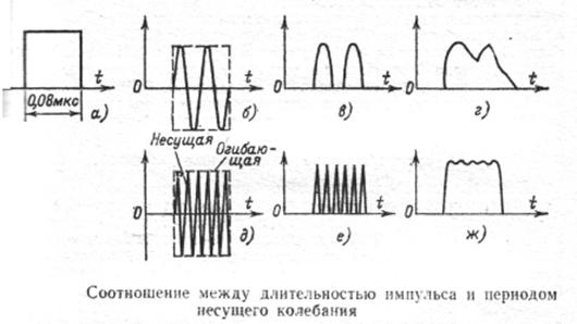
Suppose we need to transmit the shortest pulse of a television signal, which, as you know, should have a duration of 0.08 μs. Let the carrier frequency be such that during the pulse only two periods of oscillation of the carrier frequency fit. This corresponds to a carrier frequency of 2/0.08 = 25 MHz. To play an envelope (in this case- pulse) in the receiving channel of the TV, a detector is used, which, roughly speaking, first generates a sequence of positive (or negative half-waves of the carrier frequency, and then smoothes these half-waves using an RC filter.
For a carrier frequency of 25 MHz, a distorted pulse will result. If the carrier frequency is much higher, then the pulse will be reproduced at the output of the detector with much less distortion. In practice, it is believed that the carrier frequency during amplitude modulation should be 8–10 times greater than the width of the spectrum of the modulating oscillation. If the spectrum width is about 6 - 7 MHz, then the carrier frequency should be at least 50 MHz. In accordance with these considerations, the carrier frequency of the first, lowest frequency channel was chosen to be 49.75 MHz. The wavelength of such an oscillation λ \u003d c / f \u003d 3 * 10 8 / (49.75 * 10 6) \u003d 6.03 m
Thus, for a television transmission, radio channels are needed in the ranges of meter or decimeter waves.
Conclusion
Telecommunications are one of the fastest growing areas of modern science and technology. The life of modern society is already impossible to imagine without the achievements that have been made in this industry for not much more than a hundred years of development. Distinctive feature of our time - the ever-increasing need for the transmission of information flows over long distances. This is due to many reasons, and first of all, the fact that communication has become one of the most powerful levers for managing the country's economy. At the same time, undergoing significant changes, becoming multilateral and comprehensive, the telecommunications of each country is becoming more and more integrated into the global telecommunications space.
Bibliography
1. Radio engineering methods of information transmission: Tutorial for universities / V.A. Borisov, V.V. Kalmykov, Ya.M. Kovalchuk and others; Ed. V.V. Kalmykov. M.: Radio and communication. 1990. 304p.
2. Radio communication systems: Textbook for universities / N.I. Kalashnikov, E.I. Krupitsky, I.L. Dorodnov, V.I. Nosov; Ed. N.I. Kalashnikov. M.: Radio and communication. 1988. 352p.
3. Teplyakov I.M., Roshchin B.V., Fomin A.I., Veitsel V.A. Radio systems for information transmission: Textbook for universities / M.: Radio and communication. 1982. 264p.
4. Kirillov S.N., Stukalov D.N. Digital systems processing of speech signals. Tutorial. Ryazan. RGRTA, 1995. 80s.
Hosted at http://www.
So our introductory initial course of 10 lessons has come to an end. I hope you have reached the 10th lesson, honestly completing all those simple tasks and experiments that were offered in the practical work. This last lesson will be completely devoted to oscillatory processes, the study of the nature of acoustic and electromagnetic waves and, accordingly, the basics of receiving and transmitting electromagnetic waves (radio reception - transmission). The lesson is very capacious, so I advise you to take the assimilation of information very responsibly, also because it reveals the basic basics and aspects necessary for further development and understanding of the processes occurring in transceivers. I think that after this lesson you will be able to boldly assemble the simplest direct amplification receiver and the like.
Word "radio" comes from latin radiare - to radiate or emit rays . A broadcasting station, for example, like the Sun, radiates radio waves in all directions along the radii. Only a few radio stations special purpose emit radio waves in one direction. If you came to the territory of a broadcasting station, you would first of all see a vertical openwork metal mast or wires raised high above the ground. This is an antenna. Near or nearby - a building where a transmitter is located that generates electrical vibrations high frequency which the antenna converts into radio wave energy. To the transmitter from the radio studio, and it may be far from the transmitter, there is an underground cable - well-insulated wires in a strong sheath. The studio has a microphone. Not only the voice of the announcer, the conversation of people and the sounds of music, but also the whisper, the rustle of the microphone instantly turns into electrical vibrations of sound frequency, which are fed through the cable to the transmitter. How many more transformations does the alternating current of the audio frequency undergo before the receiver turns it back into sounds. The receiver will be your first practical step towards the knowledge of radio engineering. And in order for this step to be confident, it is necessary to understand the essence of those physical phenomena that underlie the technology of radio transmission and radio reception, to talk about the nature of sound, alternating current and its properties.
About vibrations and waves
Oscillatory phenomena are born and decay around us all the time. The branch from which the bird flew off sways. Clock pendulums oscillate, swings. Under the action of the wind, trees sway, wires suspended on poles, water in lakes and seas sway. So you threw a stone on the smooth surface of the lake, and waves ran from it. What happened? The particles of water at the point of impact of the stone pressed in, displacing neighboring particles, and a ring-shaped hump formed on the surface of the water. Then, at the place where the stone fell, the water rose up, but already above the previous level - a second one appeared behind the first hump, and a depression between them. Further, the water particles continue to move alternately up and down - they oscillate, dragging more and more neighboring water particles with them. Waves are formed, diverging from their place of origin in concentric circles. I emphasize: water particles only oscillate, but do not move with the waves . This is easy to verify by throwing a chip on the oscillating surface of the water. If there is no wind or water flow, the chip will only rise and fall above the water level, not moving with the waves. Water waves can be large, i.e. strong or small - weak. We call strong waves such waves that have a large range of oscillations, as they say, large amplitudes of oscillations. Weak waves have small humps - a small amplitude. The greater the amplitude of the waves that have arisen, the greater the energy they carry. The energy of the waves generated by a thrown stone is relatively small, but it can cause the reeds and grass growing in the lake to vibrate. But we know what great damage to the shore can be produced by sea waves with large amplitudes and, consequently, high energy. These destructions are carried out precisely by the energy that the waves continuously give off to the shore. Waves can be frequent or rare. The smaller the distance between the crests of traveling waves, the shorter each individual wave. The greater the distance between the waves, the longer the wave. We call the length of a wave on water the distance between two adjacent running ridges or troughs. As the waves move away from the place of origin, their amplitudes gradually decrease, fade, but the wavelength remains unchanged. Waves on the water can also be created, for example, by plunging a stick into the water and rhythmically, in time with the vibrations of the water, lowering and raising it. And in this case, the waves will be damped. But they will exist only as long as we do not stop disturbing the surface of the water. And how do oscillations of an ordinary swing occur? You know this very well: you need to push them, so they will swing from side to side. The stronger the push, the greater the amplitude of the oscillations. These oscillations will dampen if they are not supported by additional shocks. We see such and many other similar mechanical vibrations. In nature, there are more invisible vibrations that we hear, feel in the form of sound. It is not always possible, for example, to notice the vibrations of the string of a musical instrument, but we hear how it sounds. When the wind gusts, sound is produced in the pipe. It is created by oscillatory movements of air in the pipe, which we do not see. A tuning fork, a glass, a spoon, a plate, a student's pen, a sheet of paper sound - they also oscillate. Yes, we live in the world of sounds, because many bodies around us vibrate and sound. How do sound waves form in air? Air is made up of invisible particles. With the wind, they can be carried over long distances. But they can also fluctuate. For example, if we make a sharp movement with a stick in the air, then we will feel a slight gust of wind and at the same time hear a faint sound. This sound is the result of vibrations of air particles excited by vibrations of the stick. Let's do this experiment. Let's pull a string, for example, of a guitar, and then let it go. The string will begin to tremble - oscillate around its original resting position. Sufficiently strong vibrations of the string are noticeable to the eye. Weak vibrations of the string can only be felt as a slight tickle if you touch it with your finger. As long as the string vibrates, we hear the sound. As soon as the string calms down, the sound will die out. The birth of sound here is the result of condensation and rarefaction of air particles. Oscillating from side to side, the string crowds, as it were, presses air particles in front of it, forming areas in some of its volume. high blood pressure, and behind, on the contrary, areas of low pressure. These are sound waves. Propagating in the air at a speed of about 340 m/s, they carry a certain amount of energy. At the moment when the area of increased pressure of the sound wave reaches the exit, it presses on the eardrum, slightly bending it inward. When the rarefied region of the sound wave reaches the ear, the tympanic membrane curves somewhat outward. The eardrum constantly vibrates in time with alternating areas of high and low air pressure. These vibrations are transmitted along the auditory nerve to the brain, and we perceive them as sound. The greater the amplitude of sound waves, the more energy they carry in themselves, the louder the sound we perceive. Sound waves, like water or electrical vibrations, are represented by a wavy line - a sinusoid. Its humps correspond to areas of high pressure, and its troughs correspond to areas of low air pressure. The area of high pressure and the area of low pressure following it form a sound wave. We also live in a world of electromagnetic vibrations emitted by electrical appliances and all the wires in which alternating current flows, a huge number of radio station antennas, atmospheric electrical discharges, the bowels of the Earth and the infinite Cosmos. Only with the help of man-made instruments, they can be detected and recorded.
Period, frequency, amplitude of oscillations
The most important parameter characterizing mechanical, sound, electrical, electromagnetic and all other types of vibrations is period - the time it takes for one complete oscillation . If, for example, the pendulum of clocks makes two complete oscillations in 1 s, the period of each oscillation is 0.5 s. The period of oscillation of a large swing is about 2 s, and the period of oscillation of a string can be from tenths to ten-thousandths of a second. Another parameter characterizing fluctuations is frequency (from the word "often") - a number showing how many complete oscillations per second the clock pendulum, the sounding body, the current in the conductor, etc. make. The frequency of oscillations is measured by a unit called Hertz (abbreviated as Hz): 1 Hz is one oscillation per second. If, for example, a sounding string makes 440 full vibrations in 1 s (while it creates the tone “la” of the third octave), they say that its vibration frequency is 440 Hz. Frequency alternating current electrical lighting network 50 Hz. With this current, the electrons in the wires of the network during a second flow alternately 50 times in one direction and the same number of times in the opposite direction, that is, they complete 50 complete oscillations in 1 s. Larger frequency units are kilohertz (written kHz) equal to 1000 Hz and megahertz (written MHz) equal to 1000 kHz or 1000000 Hz. By the frequency of vibrations of the sounding body, one can judge the tone or pitch of the sound. The higher the frequency, the higher the tone of the sound, and vice versa, the lower the frequency, the lower the tone of the sound. Our ear is able to respond to a relatively small band (section) of frequencies of sound vibrations - from about 20 Hz to 20 kHz. Nevertheless, this frequency band accommodates the entire wide range of sounds created by the human voice, a symphony orchestra: from very low tones, similar to the sound of a beetle buzzing, to the barely perceptible high-pitched squeak of a mosquito. Oscillations with a frequency of up to 20 Hz, called infrasonic, and above 20 kHz, called ultrasonic, we do not hear. And if the tympanic membrane of our ear turned out to be able to respond to ultrasonic vibrations, we could then hear the squeak of bats, the voice of a dolphin. Dolphins emit and hear ultrasonic vibrations with frequencies up to 180 kHz. But, do not confuse the pitch, i.e. the tone of the sound, with its strength. The pitch of the sound does not depend on the amplitude, but on the frequency of vibrations. A thick and long string of a musical instrument, for example, creates a low tone of sound, that is, it oscillates more slowly than a thin and short one.
a string that produces a high pitched sound. It will help you to understand this issue (Fig. 1). In electrical and radio engineering, alternating currents with a frequency of several hertz to thousands of gigahertz are used. Broadcast radio antennas, for example, are fed with currents ranging from about 150 kHz to 100 MHz. These rapidly changing oscillations, called radio frequency oscillations, are the means by which sounds are transmitted over long distances without wires. The entire huge range of alternating currents is usually divided into several sections - subranges. Currents with a frequency of 20 Hz to 20 kHz, corresponding to oscillations that we perceive as sounds of different tonality, are called currents (or oscillations) of audio frequency, and currents with a frequency higher than 20 kHz are called ultrasonic frequency currents. Currents with frequencies from 100 kHz to 30 MHz are called high frequency currents, and currents with frequencies above 30 MHz are called ultrahigh and ultrahigh frequency currents. Remember these boundaries and the names of subranges of frequencies of alternating currents.
What are radio waves?
Suppose you pick up the handset of a telephone, dial or call desired number. Soon you hear the voice of a friend, and he - yours. What electrical phenomena occur during your telephone conversation? The sound vibrations of the air created by you are converted by the microphone into electrical vibrations of sound frequency, which are transmitted through wires to the equipment of your interlocutor. There, at the other end of the line, with the help of the phone's emitter, they are converted into air vibrations perceived by your friend as sounds. In telephony, the means of communication are wires; in radio broadcasting, radio waves. The "heart" of the transmitter of any radio station is a generator - a device that generates oscillations of a high, but strictly constant frequency for a given radio station. These radio frequency oscillations, amplified to the required power, enter the antenna and excite electromagnetic oscillations of exactly the same frequency in the surrounding space - radio waves. The speed of removal of radio waves from the antenna of the radio station is equal to the speed of light: 300,000 km / s, which is almost a million times faster than the propagation of sound in air. This means that if a transmitter is turned on at a Moscow broadcasting station at some point in time, then its radio waves will reach Vladivostok in less than 1/30 s, and the sound during this time will have time to propagate only 10 - 11 m. Radio waves propagate not only in the air, but also where there is none, for example, in outer space. In this they differ from sound waves, for which air or some other dense medium, such as water, is absolutely necessary. When a broadcasting station starts its transmissions, the announcer sometimes reports that this radio station operates on a wave of such and such a length. We see a wave running on the surface of the water, and with a certain dexterity we can measure its length. The length of radio waves can only be measured with the help of special instruments or calculated mathematically, if, of course, the frequency of the current that excites these waves is known. The length of the radio wave is the distance over which the energy of the electromagnetic field propagates during the period of current fluctuation in the antenna of the radio station. This is how it should be understood. During one period of current in the transmitter antenna in the space around it, one radio wave arises. The higher the frequency of the current, the more consecutive radio waves are emitted by the antenna during each second. Let's say the frequency of the current in the antenna of the radio station is 1 MHz. This means that the period of this current and the electromagnetic field excited by it is equal to one millionth of a second. For 1 s, a radio wave travels a distance of 300,000 km, or 300,000,000 m. In one millionth of a second, it will travel a distance a million times less, i.e. 300,000,000: 1,000,000. Therefore, the wavelength of this radio station is 300 m. So, the wavelength of a radio station depends on the frequency of the current in its antenna: the higher the frequency of the current, the shorter the wave, and vice versa, the lower the frequency of the current, the longer the wave. To find out the wavelength of a radio station, it is necessary to divide the propagation speed of radio waves, expressed in meters, by the frequency of the current in its antenna. Conversely, to find out the frequency of the current in the antenna of a radio station, it is necessary to divide the propagation speed of radio waves by the wavelength of this radio station. To convert the transmitter current frequency in megahertz to a wavelength in meters and vice versa, it is convenient to use the following formulas: ? (m) \u003d 300 / f (MHz); f (MHz) = 300 / ?, (m), where? (Greek letter "lambda") - wavelength; f is the oscillation frequency, 300 is the propagation speed of radio waves, expressed in thousands of kilometers per second. I want to warn you: do not confuse the concept of the wavelength at which a radio station operates with its range, that is, with the distance at which the transmissions of this station can be received. The range of a radio station, however, depends on the wavelength, but is not identified with it. Thus, the transmission of a station operating on a wave length of several tens of meters can be heard at a distance of several thousand kilometers, but is not always audible at closer distances. At the same time, the transmission of a radio station operating on a wave length of hundreds and thousands of meters is often not audible at such large distances as the transmissions of shortwave stations are audible. So, each broadcasting station operates on a specific frequency assigned to it, called the carrier. The wavelengths of different radio stations are not the same, but are strictly constant for each of them. This makes it possible to receive transmissions of each radio station separately, and not all at the same time.
Broadcasting. Broadcast wave bands
A very wide section of radio waves reserved for broadcasting stations is conventionally divided into several ranges: long-wave (abbreviated as LW), medium-wave (abbreviated as MW), co-wave (abbreviated as KB), ultra-short-wave (VHF). In the CIS countries, the long-wave range covers radio waves with a length of 735.3 to 2000 m, which corresponds to frequencies of 408-150 kHz; medium wave - radio waves with a length of 186.9 to 571.4 m (radio frequencies 1605 - 525 kHz); shortwave - radio waves with a length of 24.8 to 75.5 (radio frequencies 12.1 - 3.95 MHz); ultrashortwave - radio waves from 4.11 to 4.56 m long (radio frequencies 73 - 65.8 MHz). VHF radio waves are also called meter waves; in general, all waves shorter than 10 m are called ultrashort waves. Television broadcasts are conducted in this range, communications radio stations equipped on fire brigade vehicles, taxis, home health services, etc. operate in this range. The radio frequencies of short-wave broadcasting stations are unevenly distributed over the range: more all of them operate on waves with a length of about 25, 31, 41 and 50 m. Accordingly, therefore, the shortwave broadcasting range is divided into 25, 31, 41 and 50-meter subbands. According to an international agreement, a 600 m (500 kHz) wave is reserved for the transmission of distress signals by ships at sea - SOS. All maritime emergency radio transmitters operate on this wave, the receivers of rescue stations and lighthouses are tuned to this wave.
Broadcast
If complex technical equipment broadcasting station is simplified in the form of conventional signs and rectangles, then its block diagram will be obtained in the form shown in Fig. 2. Here are five main instruments and devices: studio microphone, audio frequency amplifier (3CH), radio frequency (RF) oscillator, radio frequency oscillator power amplifier and antenna, emitting electromagnetic energy of radio waves. While the studio microphone is not turned on, a current of high (carrier) but strictly constant frequency and amplitude flows in the station antenna (see the left parts of the graphs in Fig. 3). The antenna emits radio waves of constant length and power. But in the studio they turned on the microphone, and people who were tens, hundreds and thousands of kilometers from the radio station heard the familiar voice of the announcer.
What happens at this time in the transmitter of the radio station? Sound frequency oscillations created by a microphone and amplified by a 3-hour studio amplifier are fed to the so-called modulator, which is part of the transmitter power amplifier, and there, acting on the high-frequency current of the generator, change its oscillation amplitude. From this, the electromagnetic energy radiated by the transmitter antenna changes (see the right parts of the graphs in Fig. 3). The higher the frequency of the current coming from the radio studio to the transmitter, the more frequently the amplitudes of the current in the antenna change. So the sound, converted by the microphone into electrical vibrations of the sound frequency, receives a "ticket" to the air. The process of changing the amplitudes of high-frequency oscillations under the influence of an audio frequency current is called amplitude modulation (AM). The high-frequency currents in the antenna that change in amplitude and the radio waves emitted by it are called modulated radio frequency oscillations. In addition to amplitude modulation, there is also the so-called frequency modulation (FM). With this type of modulation, the frequency changes, and the amplitude of the radio frequency oscillations in the radio station antenna remains unchanged. Frequency modulation is used, for example, to transmit sound in television, in radio broadcasting on VHF. In broadcasting on LW, MW and HF, only amplitude modulation is used. Radio waves cannot be detected by any of our senses. But if a conductor meets on their way, they give him a part of their energy. The reception of radio broadcasts is based on this phenomenon. The radio receiver antenna captures the energy of radio waves. Giving the antenna part of the electromagnetic energy, radio waves induce modulated radio frequency oscillations in it. In the receiver, processes are reversed to those that occur in the studio and on the transmitter of the radio station. If there the sound is sequentially converted first into electrical oscillations of sound frequency, and then into modulated oscillations of radio frequency, then the inverse problem is solved during radio reception: the modulated oscillations of radio frequency excited in the antenna are converted by the receiver into electrical oscillations of sound frequency, and then into sound. In the simplest receiver, which operates only due to the energy captured by the antenna, modulated radio frequency oscillations are converted into audio frequency oscillations by the detector, and these oscillations into sound by headphones. But after all, the radio waves of many radio stations penetrate the antenna of the receiver, exciting in it modulated oscillations of a wide variety of radio frequencies. And if all these radio signals were converted into sounds, then we would hear hundreds of voices of people speaking different languages. It is unlikely that such radio reception suited us. Of course, it is interesting to listen to the transmissions of different stations, but only, of course, not all at the same time, but each one separately. And for this, from the oscillations of all frequencies excited in the antenna, it is necessary to single out oscillations with the frequency of the radio station whose transmissions we want to listen to. This task is performed oscillatory circuit, which is an indispensable part of both the simplest and the most complex broadcasting receiver. It is with the help of an oscillatory circuit that you will tune your first receiver to radio signals of different wavelengths.
Propagation of radio waves
Now consider some features of the propagation of radio waves. The fact is that radio waves of different ranges have different properties that affect the range of their propagation. Waves of one length travel long distances, waves of another length are "lost" beyond the horizon. It happens that the radio signal is perfectly audible somewhere on the other side of the Earth or in Space, but it cannot be detected a few tens of kilometers from the radio station. How can this be explained? What affects the "range" of radio waves of different lengths? Earth and its surrounding atmosphere. Earth is a current conductor , although not as good as, say, copper wires. The earth's atmosphere consists of three layers. The first layer, the upper boundary of which ends 10 - 12 km from the Earth's surface, is called the troposphere. Above it, up to 50 kilometers from the surface of the Earth, the second layer is the stratosphere. And above, up to about 400 km above the Earth, the third layer of the ionosphere extends (Fig. 4). The ionosphere plays a decisive role in the propagation of radio waves, especially short ones.
The air in the ionosphere is very rarefied. Under the action of solar radiation there, many free electrons are released from the atoms of gases, as a result of which positive ions appear. There is, as they say, ionization of the upper layer of the atmosphere. The ionized layer is able to absorb radio waves and bend their path. During the day, depending on the intensity of solar radiation, the number of free electrons in the ionized layer, its thickness and height change, and this changes the electrical properties of this layer. Radio station antennas radiate radio waves along the Earth's surface and up at various angles to it. Waves traveling along the surface are called ground or surface , at various angles - spatial . When transmitting signals from DW stations, mainly the energy of surface waves is used, which well envelop the Earth's surface. But the Earth, being a conductor, absorbs the energy of radio waves. Therefore, as the distance from the Far East stations increases, the volume of reception of its transmissions gradually decreases, and, finally, the reception stops completely. Medium waves bend around the Earth worse and, moreover, are absorbed by it more strongly than long ones. This explains the lower "range" of NE broadcasting stations compared to LW stations. So, for example, the signals of a radio station operating on a wave length of 300 - 400 m can be received at a distance two to three times less than the signals of a station of the same power, but operating on a wave length of 1500 - 2000 m. To increase the range NE stations, it is necessary to increase their power. In the evening and at night, the transmission of LW and MW radio stations can be heard at greater distances than during the day. The fact is that the part of the radio wave energy emitted upwards by these stations is lost without a trace in the atmosphere during the day. After sunset, the lower layer of the ionosphere bends their path so that they return to the Earth at such distances at which the reception of these stations by surface waves is no longer possible. Radio waves in the shortwave range are strongly absorbed by the Earth and poorly bend around its surface. Therefore, already at a distance of several tens of kilometers from such radio stations, their surface waves attenuate. But on the other hand, sky waves can be detected by receivers at a distance of several thousand kilometers from them and even at the opposite point of the Earth. The curvature of the path of spatial short waves occurs in the ionosphere. Having entered the ionosphere, they can go a very long way in it and return to Earth far from the radio station. They can make trip around the world- they can be received even in the place where the transmitting station is located. This explains the secret of good propagation of short waves over long distances even at low transmitter powers. But with the propagation of short waves, zones can form where HF radio transmissions are not audible at all. They are called zones of silence (see Fig. 4). The length of the zone of silence depends on the wavelength and the state of the ionosphere, which in turn depends on the intensity of solar radiation. Ultrashort waves in their properties are closest to light rays. They mainly propagate in a straight line and are strongly absorbed by the earth, flora, various structures, and objects. Therefore, reliable reception of VHF station signals by a surface wave is possible mainly only when a straight line can be mentally drawn between the antennas of the transmitter and receiver, which does not encounter any obstacles in the form of mountains, hills, forests along the entire length. The ionosphere for VHF is like glass for light - it is “transparent”. ultrashort waves pass almost unhindered through it. Therefore, this range of radio waves is used to communicate with artificial Earth satellites and spacecraft.
How does a radio receiver work?
In any simple broadcast receiver, regardless of its complexity, there are absolutely three elements that ensure its performance. These elements are oscillatory circuit, detector and telephones or, if the receiver is with a 3-hour amplifier, a direct-radiating dynamic head. Oscillatory circuit: - the device of the simplest oscillatory circuit and its circuit are shown in fig. 5. As you can see, it consists of a coil L and a capacitor C, which form a closed electrical circuit in which, under certain conditions, electrical oscillations can arise and exist in the circuit. Therefore, it is called an oscillatory circuit.
Have you ever observed such a phenomenon: at the moment the power of the electric lighting lamp is turned off, a spark appears between the opening contacts of the switch. If you accidentally connect the terminals of the poles of the battery of an electric flashlight (which must be avoided), at the moment of their separation, a small spark also jumps between them. And in factories, in the workshops of factories, where electric circuits are broken with knife switches, through which currents flow great strength, sparks can be so significant that care must be taken so that they do not harm the person who turns on the current. Why are these sparks generated? You already know that there is a magnetic field around a current-carrying conductor, which can be depicted as closed magnetic lines of force penetrating the surrounding space. To detect this field, if it is constant, you can use the magnetic needle of the compass. If the conductor is disconnected from the current source, then its disappearing magnetic field, dissipating in space, will induce currents in other conductors closest to it. The current is also induced in the conductor that created the EMF, the magnetic field. And since it is in the very thick of its own magnetic lines of force, a stronger current will be induced in it than in any other conductor. The direction of this current will be the same as it was at the moment of breaking the conductor. In other words, the disappearing magnetic field will support the current that creates it until it disappears itself, i.e. the energy contained in it is not completely used up. Consequently, the current in the conductor also flows after the current source is turned off, but, of course, not for long - a negligible fraction of a second. After opening the circuit, electric current may flow for some time through the air gap between the disconnected ends of the conductor, between the contacts of the switch or knife switch. It is this current through the air that forms an electric spark. This phenomenon is called self-induction , A electrical force(do not confuse with the phenomenon of induction, familiar to you from previous lessons), which, under the influence of its disappearing magnetic field, maintains a current in it, - electromotive force self-induction or, for short, self-induction emf . The greater the EMF of self-induction, the more significant the spark can be at the point of breaking the electrical circuit. The phenomenon of self-induction is observed not only when the current is turned off, but also when the current is turned on. In the space surrounding the conductor, the magnetic field arises immediately when the current is turned on, at first it is weak, but then it increases very quickly. The increasing magnetic field of the current also excites the self-induction current, but this current is directed towards the main current. The self-induction current prevents the instantaneous increase in the main current and the growth of the magnetic field. However, after a short period of time, the main current in the conductor overcomes the oncoming self-induction current and reaches its maximum value, the magnetic field becomes constant and the self-induction stops. The phenomenon of self-induction can be compared with the phenomenon of inertia. Sledges, for example, are difficult to budge. But when they pick up speed, stock up on kinetic energy - the energy of movement, they cannot be stopped instantly. When braking, the sled continues to slide until the energy stored by them is used up to overcome friction on the snow. Do all conductors have the same self-inductance? No The longer the conductor, the greater the self-induction . In a conductor wound into a coil, the phenomenon of self-induction is more pronounced than in a straight conductor, since the magnetic field of each turn of the coil induces a current not only in this turn, but also in neighboring turns of this coil. The longer the wire in the coil, the longer the self-induction current will exist in it after the main current is turned off. Conversely, it will take more time after the main current is turned on for the current in the circuit to increase to a certain value and to establish a constant magnetic field. Remember: the property of a conductor to influence the current in the circuit and change its value is called inductance, and the coils in which this property is most pronounced are self-induction or inductance coils. The greater the number of turns and the size of the coil, the greater its inductance, the more it affects the current in the electrical circuit. So, the inductor prevents both the increase and decrease of current in the electrical circuit. It is still in the DC circuit, and its influence is felt only when the current is turned on and off. In an alternating current circuit, where the current and its magnetic field are constantly changing, the self-induction EMF of the coil acts all the time while the current is flowing. This is an electrical phenomenon and is used in the first element of the receiver's oscillatory circuit - the inductor. The second element of the oscillatory circuit of the receiver is the storage of electric charges - a capacitor. The simplest capacitor consists of two conductors electric current, for example: - two metal plates, called capacitor plates, separated by a dielectric for example: - air or paper. The larger the area of the capacitor plates and the closer they are located to each other, the greater the electrical capacitance of this device. If a direct current source is connected to the capacitor plates (Fig. 6, a), then in the resulting circuit there will be short-term current and the capacitor will be charged to a voltage equal to the voltage of the current source. You may ask: why does a current occur in a circuit where there is a dielectric? When we connect a current source to the capacitor, the electrons in the conductors of the formed circuit begin to move towards the positive pole of the current source, forming a short-term flow of electrons in the entire circuit. As a result, the capacitor plate, which is connected to the positive pole of the current source, is depleted in free electrons and is positively charged, while the other plate is enriched in free electrons and, therefore, is charged negatively. As soon as the capacitor is charged, the short-term current in the circuit, called the capacitor charging current, will stop.
 |
| Rice. 6 The process of charging - discharging the capacitor. |
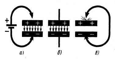
If the current source is disconnected from the capacitor, then the capacitor will be charged (Fig. 6, b). The transfer of excess electrons from one plate to another is prevented by a dielectric. There will be no current between the plates of the capacitor, and the electrical energy accumulated by it will be concentrated in the electric field of the dielectric. But it is worth connecting the plates of a charged capacitor with some kind of conductor (Fig. 6, c), the “extra” electrons of the negatively charged plate will pass through this conductor to another plate, where they are missing, and the capacitor will be discharged. In this case, a short-term current also occurs in the resulting circuit, called the capacitor discharge current. If the capacitance of the capacitor is large, and it is charged to a significant voltage, the moment of its discharge is accompanied by the appearance of a significant spark and crackling. The property of a capacitor to accumulate electrical charges and discharge through conductors connected to it is used in the oscillatory circuit of a radio receiver. And now, remember the ordinary swing. You can swing on them so that "it takes your breath away." What needs to be done for this? First push to bring the swing out of rest, and then apply some force, but always only in time with their oscillations. Without much difficulty, you can achieve strong swing swings - get large amplitudes of oscillation. Even a small boy can swing an adult on a swing if he applies his strength skillfully. Having swung the swing harder, in order to achieve large amplitudes of oscillations, we will stop pushing them. What will happen next? Due to the stored energy, they swing freely for some time, the amplitude of their oscillations gradually decreases, as they say, fluctuations are damped , and finally the swing will stop. At free vibrations swing, as well as a freely suspended pendulum - the stored potential energy goes into the kinetic energy of motion, which in the extreme top point again passes into the potential, and after a fraction of a second - again into the kinetic. And so on until the entire supply of energy is used up to overcome the friction of the ropes in the places where the swing is suspended and air resistance. At any large stock energy, free oscillations are always damped: with each oscillation their amplitude decreases and the oscillations gradually completely die out - the swing stops. But the period, i.e., the time during which one oscillation occurs, and hence the frequency of oscillations, remain constant. However, if the swing is constantly pushed in time with its oscillations and thereby replenishes the energy lost to overcome various braking forces, the oscillations will become undamped. It's no longer free, but forced vibrations . They will last until the external pushing force ceases to act. I mentioned swings here because the physical phenomena that occur in such a mechanical oscillatory system are very similar to those in an electrical oscillatory circuit. In order for electrical oscillations to arise in the circuit, it must be given energy that would “push” the electrons in it. This can be done by charging, for example, its capacitor. Let's break the oscillatory circuit with the switch S and connect a direct current source to the plates of its capacitor, as shown in (Fig. 7 on the left). The capacitor will charge up to GB battery voltage. Then we disconnect the battery from the capacitor and close the circuit with switch S.
The phenomena that will now occur in the circuit are depicted graphically in (Fig. 7 on the right). At the moment the circuit is closed by the switch, the upper plate of the capacitor has a positive charge, and the lower one has a negative charge (Fig. 7, a). At this time (point 0 on the graph) there is no current in the circuit, and all the energy accumulated by the capacitor is concentrated in the electric field of its dielectric. When the capacitor is closed to the coil, the capacitor will begin to discharge. A current appears in the coil, and a magnetic field appears around its turns. By the time the capacitor is completely discharged (Fig. 7, b), marked on the graph by the number 1, when the voltage on its plates decreases to zero, the current in the coil and the energy of the magnetic field will reach the highest values. It would seem that at this moment the current in the circuit should have stopped. This, however, will not happen, since from the action of the self-induction EMF, which seeks to maintain the current, the movement of electrons in the circuit will continue. But only until all the energy of the magnetic field is used up. In the coil at this time, an induced current, decreasing in value, but of the initial direction, will flow. By the time marked on the graph by the number 2, when the energy of the magnetic field is used up, the capacitor will again be charged, only now there will be a positive charge on its lower plate, and a negative charge on the upper one (Fig. 7, c). Now the electrons will begin to move in the opposite direction - in the direction from the upper plate through the coil to the lower plate of the capacitor. By time 3 (Fig. 7, d), the capacitor will be discharged, and the magnetic field of the coils will reach its maximum value. And again, the self-induction EMF will “drive” electrons along the coil wire, thereby recharging the capacitor. At time 4 (Fig. 7, e), the state of the electrons in the circuit will be the same as at the initial moment - 0. One complete oscillation has ended. Naturally, the charged capacitor will again be discharged to the coil, recharged, and the second, followed by the third, fourth oscillations will occur. In other words, an alternating electric current, electrical oscillations, will appear in the circuit. But this oscillatory process in the circuit is not infinite. It continues until all the energy received by the capacitor from the battery is used to overcome the resistance of the coil wire of the circuit. The oscillations of the circuit are free and, therefore, damped. What is the frequency of such oscillations of electrons in the circuit? To understand this issue in more detail, I advise you to conduct such an experiment with a simple pendulum. Hang on a thread 100 cm long a ball made of plasticine, or another load weighing 20 - 40 g (in Fig. 8, the length of the pendulum is indicated by the Latin letter L).
Remove the pendulum from its equilibrium position and, using a clock with a second hand, count how many complete oscillations it makes in 1 minute. Approximately 30. Therefore, the oscillation frequency of this pendulum is 0.5 Hz, and the period is 2 s. During the period, the potential energy of the pendulum twice passes into the kinetic, and the kinetic into the potential. Cut the thread in half. The frequency of the pendulum will increase by about one and a half times and the oscillation period will decrease by the same amount. This experience allows us to conclude: with a decrease in the length of the pendulum, the frequency of its natural oscillations increases, and the period decreases proportionally. By changing the length of the pendulum suspension, achieve that its oscillation frequency is 1 Hz. This should be with a thread length of about 25 cm. In this case, the period of oscillation of the pendulum will be equal to 1 s. No matter how you try to create the initial swing of the pendulum, the frequency of its oscillations will be unchanged. But one has only to shorten or lengthen the thread, as the oscillation frequency will immediately change. With the same thread length, there will always be the same oscillation frequency. This is the natural frequency of the pendulum. You can get a given oscillation frequency by choosing the length of the thread. The oscillations of the thread pendulum are damped. They can become undamped only if the pendulum is slightly pushed in time with its oscillations, thus compensating for the energy that it expends on overcoming the resistance exerted by the air, the energy of friction, the earth's gravity. The natural frequency is also characteristic of the electric oscillatory circuit. It depends, firstly, on the inductance of the coil. The greater the number of turns and the diameter of the coil, the greater its inductance, the greater will be the duration of the period of each oscillation. The natural frequency of oscillations in the circuit will be correspondingly less. And, conversely, with a decrease in the inductance of the coil, the period of oscillation will be reduced - the natural frequency of oscillation in the circuit will increase. Secondly, the natural frequency of oscillations in the circuit depends on the capacitance of its capacitor. The larger the capacitance, the more charge the capacitor can accumulate, the more time it takes to recharge it, the lower the oscillation frequency in the circuit. With a decrease in the capacitance of the capacitor, the frequency of oscillations in the circuit increases. Thus, natural frequency damped oscillations in the circuit can be controlled by changing the inductance of the coil or the capacitance of the capacitor. But in an electric circuit, as well as in a mechanical oscillatory system, undamped ones can also be obtained, i.e. forced oscillations, if at each oscillation the circuit is replenished with additional portions of electrical energy from any source of alternating current. How, then, are undamped electrical oscillations excited and maintained in the receiver circuit? Radio frequency oscillations excited in the receiver antenna. These oscillations give the circuit its initial charge, and they also support the rhythmic oscillations of the electrons in the circuit. But the strongest undamped oscillations in the receiver circuit occur only at the moment of resonance of the natural frequency of the circuit with the frequency of the current in the antenna. What does it mean? People of the older generation say that in St. Petersburg, the Egyptian bridge collapsed from soldiers walking in step. And it could happen, apparently, under such circumstances. All the soldiers paced rhythmically across the bridge. The bridge began to sway from this - to oscillate. By a coincidence, the natural frequency of the bridge coincided with the step frequency of the soldiers, and the bridge is said to have entered resonance . The rhythm of the building informed the bridge more and more portions of energy. As a result, the bridge swayed so much that it collapsed: the coherence of the military system harmed the bridge. If there were no resonance of the natural frequency of the bridge with the step frequency of the soldiers, nothing would have happened to the bridge. Therefore, by the way, when soldiers pass through weak bridges, it is customary to give the command to “knock off their leg.” And here is the experience. Step up to some string musical instrument and loudly shout "a": one of the strings will respond - it will sound. The one that is in resonance with the frequency of this sound will vibrate stronger than the other strings - it will respond to the sound. Another experiment with a pendulum. Stretch a thin rope horizontally. Tie the same pendulum of thread and plasticine to it (Fig. 9).
Throw another similar pendulum over the rope, but with a longer thread. The length of the suspension of this pendulum can be changed by pulling the free end of the thread by hand. Bring the pendulum into oscillatory motion. In this case, the first pendulum will also begin to oscillate, but with a smaller amplitude. Without stopping the oscillations of the second pendulum, gradually reduce the length of its suspension - the amplitude of oscillations of the first pendulum will increase. In this experiment, illustrating the resonance of mechanical vibrations, the first pendulum is the receiver of vibrations excited by the second pendulum. The reason forcing the first pendulum to oscillate is periodic oscillations of the extension with a frequency equal to the oscillation frequency of the second pendulum. The forced oscillations of the first pendulum will have a maximum amplitude, and its natural frequency will coincide with the oscillation frequency of the second. Such or similar phenomena, only, of course, of electrical origin, are also observed in the oscillatory circuit of the receiver. From the action of the waves of many radio stations, currents of various frequencies are excited in the receiving antenna. From all the radio frequency fluctuations, we need to choose only the carrier frequency of the radio station whose transmissions we want to listen to. To do this, you should choose the number of turns of the coil and the capacitance of the capacitor of the oscillatory circuit so that its natural frequency coincides with the frequency of the current created in the antenna by the radio waves of the station of interest to us. In this case, the strongest oscillations will occur in the circuit with the carrier frequency of the radio station to which it is tuned. That's what it is tuning the receiver circuit to resonance with the frequency of the transmitting station . In this case, the signals of other stations are not audible at all or are heard very quietly, since the oscillations excited by them in the circuit will be many times weaker. Thus, by tuning the circuit of your receiver into resonance with the carrier frequency of the radio station, you use it, as it were, to select, highlighting frequency fluctuations, only of this station. The better the circuit will select the desired oscillations from the antenna, the higher the selectivity of the receiver, the weaker the interference from other radio stations will be. Until now, I have told you about a closed oscillatory circuit, i.e. circuit, the natural frequency of which is determined only by the inductance of the coil and the capacitance of the capacitor forming it. However, the receiver input circuit also includes the antenna and ground. This is no longer a closed, but an open oscillatory circuit. The fact is that the antenna wire and the ground are "plates" of a capacitor that has some electrical capacitance. Depending on the length of the wire and the height of the antenna above the ground, this capacitance can be several hundred picofarads. But after all, the antenna and the earth can also be considered as not a complete coil of a large coil. Therefore, the antenna and ground, taken together, also have inductance. And the capacitance together with the inductance form an oscillatory circuit (Fig. 10).
Such a circuit, which is open oscillatory circuit , also has its own frequency of oscillation. By including inductors and capacitors between the antenna and ground, we can change its natural frequency, tune it into resonance with the frequencies of different radio stations. How this is done in practice, you already know. I will not be mistaken if I say that the oscillating circuit is the "heart" of the radio receiver. And not just the radio. That's why I gave him more attention. I turn to the second element of the receiver - the detector.
Radio signal detector and detection
The detector is a two-electrode semi-conductive device (high-frequency diode) with one-sided electrical conductivity: it conducts current in one direction well and does not conduct or weakly conducts current in the opposite direction. To simplify the explanation of the operation of the diode as a detector, we will assume that it does not conduct the reverse current at all and is, as it were, an insulator for it. This property of the diode is illustrated by the graph shown in (Fig. 11), the diode freely passes through itself positive half-waves of alternating current and does not pass negative half-waves at all. The negative half-waves of the diode, as it were, cut off. As a result of this action of the diode, the alternating current is converted into a pulsating current in one direction, but changing in magnitude with the frequency of the current passed through it. This conversion process, called AC rectification, underlies the detection of received radio signals.
Look at the graphs shown in (Fig. 12). They illustrate the processes occurring in the detector circuit of the simplest receiver. Under the action of radio waves, modulated radio frequency oscillations are excited in the receiver circuit (Fig. 12, a). A circuit is connected to the circuit, consisting of a diode and telephones.
For this circuit, the oscillatory circuit is a source of radio frequency alternating current. Since the diode passes current in only one direction, the modulated radio frequency oscillations entering its circuit will be rectified by it (Fig. 12, b), in other words, detected. If you draw a dashed line around the top of the rectified current, you get a "pattern" of the audio frequency current, which modulates the current entering the radio station antenna during transmission. The current resulting from the detection consists of radio frequency pulses, the amplitudes of which change with the sound frequency. It can be considered as a total current and decomposed into two components: high frequency and low frequency . They are called, respectively, the high-frequency and the audio frequency component of the pulsating current. In the simplest receiver, the audio frequency component goes through the telephones and is converted by them into sound.
Headphone and its device
The telephone is the third, last link of the simplest receiver, which, figuratively speaking, "gives out finished products" - sound. This is one of the oldest electrical appliances, which has retained its main features almost unchanged to this day. For detector and many simple transistor receivers, headphones are used, for example, types TON-1, TG-1, TA-4. These are two phones connected in series, held on the headband. Let's unscrew the cover of one of the phones (Fig. 13, a).
Under it is a round tin plate - a membrane. Carefully removing the membrane, we will see two coils mounted on the pole pieces of a permanent magnet pressed into the housing. The coils are connected in series, and the extreme leads are soldered to the rods, to which a cord with single-pole plugs is connected from the outside with clamping screws. How does the phone work? The sound-producing membrane is located near the pole pieces of the magnet and rests on the sides of the case (Fig. 13, a). Under the action of the magnet field, it bends a little in the middle, but does not touch the pole pieces of the magnet (in Fig. 13, b) - a solid line. When current flows through the coils of the phone, it creates a magnetic field around the coils, which interacts with the magnetic field of the permanent magnet. The strength of this magnetic field, and hence the force of attraction of the membrane to the pole pieces, depends on the direction of the current in the coils. In one direction, when the directions of the magnetic field lines of the coils and the magnet coincide and their fields add up, the membrane is more strongly attracted to the poles of the magnet (in Fig. 13, b - the lower dashed line). With a different direction of current, the lines of force of the coil and the magnet are directed oppositely and the total field becomes weaker than the field of the magnet. In this case, the membrane is weaker attracted by the pole pieces and, straightening, somewhat moves away from them (Fig. 13, b - upper dashed line). If an alternating current of sound frequency is passed through the telephone coils, the total magnetic field will either increase or weaken, and the membrane will either approach the pole pieces of the magnet, then move away from them, i.e., oscillate with the frequency of the current. As it oscillates, the membrane will create sound waves in the surrounding space. At first glance, it may seem that a permanent magnet is not needed in the phone: the coils can be put on an iron non-magnetized shoe. But it's not. And that's why. An iron shoe magnetized by alternating current will attract the membrane whether the current flows through the coils in one direction or the other. This means that in one period of alternating current, the membrane will be attracted during the first half-cycle, move away from it, and be attracted again during the second half-cycle, i.e. for one period of alternating current (Fig. 14, a) it will make two oscillations (Fig. 14, b).
If, for example, the current frequency is 500 Hz, then the telephone membrane will make 500 * 2 = 1000 oscillations in 1 s and the sound tone will be distorted - it will be twice as high. It is unlikely that such a phone will suit us. With a permanent magnet, the situation is different: with one half-cycle, the magnetic field is strengthened - the already attracted membrane will bend even more; at another half-cycle, the field weakens and the membrane, straightening, moves further away from the poles of the magnet. Thus, in the presence of a permanent magnet, the membrane makes only one oscillation in one period of alternating current (Fig. 14, c) and the telephone does not distort the sound. Permanent magnet also increases the phone volume. Now let's analyze the following question: why is a blocking capacitor connected in parallel with the headphones? What is its role? The electrical capacitance of the blocking capacitor is such that high-frequency currents freely pass through it, and it provides significant resistance to audio-frequency currents. Phones, on the contrary, pass sound frequency currents well and show great resistance to high frequency currents. In this section of the detector circuit, the high-frequency pulsating current is divided (in Fig. 15 - at point a) into components that go further: high-frequency - through the blocking capacitor Сbl, and the audio frequency component through telephones. Then the components are connected (in Fig. 15 - at point b) and then again go together.
The purpose of the blocking capacitor can be explained as follows. The telephone, due to the inertness of the membrane, cannot respond to every high-frequency current pulse in the detector circuit. This means that in order for the phone to work, it is necessary to somehow “smooth out” the high-frequency pulses, “fill in” the current dips between them. This problem is solved using a blocking capacitor as follows. Individual high-frequency pulses charge the capacitor. In the moments between pulses, the capacitor is discharged through the phone, thus filling the "gaps" between the pulses. As a result, a current flows through the phone in one direction, but changing in magnitude with an audio frequency, which is converted by it into sound. Even more briefly, the role of the blocking capacitor can be said as follows: it filters the audio frequency signal isolated by the diode, i.e., “clears” it from the radio frequency component. The quality of the phone is evaluated mainly in terms of its sensitivity - the ability to respond to weak fluctuations in electric current. The weaker the vibrations to which the phone responds, the higher its sensitivity. The sensitivity of a telephone depends on the number of turns in its coils and the quality of the magnet. Two phones with exactly the same magnets, but with coils containing an unequal number of turns, are different in sensitivity. The best sensitivity will be the one in which coils with a large number of turns are used. The sensitivity of the phone also depends on the position of the membrane relative to the pole pieces of the magnet. The best sensitivity will be in the case when the membrane is very close to the pole pieces, but, vibrating, does not touch them. Phones are usually divided into high-resistance - with a large number of turns in the coils, and low-resistance - with a relatively small number of turns. Only high impedance telephones are suitable for the detector receiver. The coils of each telephone type TON-1, for example, are wound with enameled wire 0.06 mm thick and have 4000 turns. Their DC resistance is about 2200 ohms. This number, which characterizes the phones, is stamped on their cases. Since two phones are connected in series, they total resistance DC is 4400 ohms. The DC resistance of low-resistance telephones, for example, type TA - 56, can be 50 - 60 ohms. Low impedance telephones can be used for some transistorized receivers. How to check the health and sensitivity of headphones? Press them to your ears. Wet the plugs at the end of the cord with saliva, and then touch them together - a faint click should be heard in the phones. The stronger this click, the more sensitive the phones. Clicks are obtained because the wet contact between the metal plugs is a very weak source of current. A rough check of phones can be done with a battery for a flashlight. When connecting phones to the battery and disconnecting from it, sharp clicks should be heard. If there are no clicks, then somewhere in the coils or cord there is a break or bad contact.
Practical work
In this practical work, we will design the simplest radio receiver (detector receiver), without which, in my opinion, the further development of any radio receiving equipment is unthinkable. Ask any specialist in the field of radio electronics (HF - VHF radio communications) what a detector radio receiver is and I think he will give you an intelligible answer without delay. In a word, this is a classic, the basis - the basics, with which our fathers and grandfathers began. And we will try to keep up with them.
The main advantage of this version of the simplest radio receiver is that it is easy to make any changes and additions to it, to correct errors by switching the connecting conductors, since all its details will lie in front of you in expanded form. Experimenting with it will help you understand the basic principles of operation of any broadcast receiver and gain some practical skills in radio engineering. For such a receiver, you will need: an inductor, a rod made of ferrite grade 400NN or 600NN with a diameter of 7 - 8 mm and a length of 120 - 140 mm (such rods are used for magnetic antennas of transistor receivers), a semiconductor point diode, which will be a detector in the receiver, several constant capacitors containers and headphones (Fig. 1).
Make the inductor yourself (from the previous lessons you know how to do it). The rest of the details are ready. The diode can be any of the series D9, D2. Capacitors are also of any type - mica, ceramic or paper with a capacity from several tens to several thousand picofarads (abbreviated: pF). Headphones are high-resistance, that is, with windings with a resistance of 1500 - 2200 Ohms, for example, type TON - 1 or TA - 4. A little later, when you start experimenting, you will need some other details and materials. The coil will require a winding wire brand PEV - 1 (Wire with Enamel High-strength insulation in one layer), PEV - 2 (the same, but with insulation in two layers) or PEL (Wire with Enamel Varnish-resistant insulation) with a diameter of 0.15 - 0, 2 mm. The winding wires of these brands and their diameter are designated as follows: PEV - 1 0.15, PEV - 2 0.18, PEL 0.2. Winding wires of other brands are also suitable, for example, PBD - with insulation from two (letter D) layers of cotton yarn (letter B), or PELSHO - with enamel varnish-resistant insulation and one (letter O) layer of natural silk (letter Sh). It is only important that the wire insulation is intact, otherwise a short circuit may occur between the turns of the coil, which must not be allowed. The inner diameter of the coil frame, glued from writing paper in 3 - 4 layers, should be such that a ferrite rod enters it with little friction. Before winding the coil, insert the rod into the frame. Do not pull the wire too hard, otherwise the frame will shrink and it will be difficult to pull the rod out of it. In total, 300 turns of wire must be wound on the frame in one row, making bends in the form of loops every 50 turns. You get a single-layer six-sectional inductor with two extreme leads and five taps. To extreme turns the wires of the finished coil did not fall off, fasten them to the frame with rings cut from a rubber or PVC tube, or wrap them with threads. Additionally, the turns of the coil wire can be fastened with a thin layer of Moment glue. Carefully cut the ends of the frame with a sharp knife. It happens that during the winding of the coil, the wire breaks or one piece of wire is not enough for the whole coil. In this case, the ends of the wire to be connected must be stripped of insulation, tightly twisted, soldered and necessarily wrapped with a thin insulating tape. If the connection is near the tap, then it is better not to spare a few turns of wire and make it in a loop. Now, start assembling your first radio (Fig. 2).
Strip the ends of the leads and bends, coils from insulation, only carefully so as not to break the wire. We will call one of the extreme conclusions the beginning of the coil and denote it by the letter (n). Connect it to a diode. Connect the second end of the coil, its end (k), to one of the contact pins of the headphone cord. The remaining free output of the diode and the pin of the phones are also connected to each other. To the conductor going from the beginning of the coil to the diode, firmly screw the antenna wire, after stripping it of insulation. This conductor of the receiver will be called antenna. Screw the ground wire to the conductor connecting the end of the coil to the telephones. This will be the grounded conductor. During the experiments, it will have to be switched from one output of the coil to another (shown in Fig. 2 by a dashed line with an arrow), without changing the ground connections with telephones. Let's take a "walk" through the chains of the resulting receiver. From the beginning of the coil (n) along the antenna conductor, we get to the diode, and from it to the headphones. Through the phones, then along the grounded conductor and through all the turns of the coil we come to the starting point (n). It turned out closed electrical circuit, consisting of a coil, a diode and telephones. They call her detector . If there is an open somewhere in this circuit, poor contact between parts or connecting conductors, for example, loose twisting, the receiver, of course, will not work. The shortest path from the antenna to ground is through the coil. A high-frequency current excited in the antenna by radio waves will go along this path. This current will create a high-frequency voltage at the ends of the coil, which will induce a current of the same frequency in the entire detector circuit. A circuit consisting of an antenna, a coil and ground is called an antenna or an antenna circuit. Please note: the receiver loop coil is included in both the antenna and detector circuits. After such a walk through the circuits of the receiver, you can proceed to its test. Put the phones on your head, press them closer to your ears, listen. It is possible that you will not hear anything right away even with a known good antenna and grounding, pre-tested diode and telephones. This is because the receiver does not seem to be tuned to the carrier frequency of a broadcasting station that is well heard in your area, or you are caught in a transmission break. You can tune such a receiver by changing the number of turns of the coil included in the antenna circuit. In (Fig. 2), all 300 turns of the coil are included in the antenna circuit. If the grounded conductor is disconnected from the end of the coil and connected, for example, to tap 5, then not 300, but 250 turns will be included in the circuit. If this conductor is switched to tap 4, 200 turns will be included in the circuit. When switching it to tap 3, 150 turns will be included in the antenna circuit, and so on. In this case, the lower sections will not be included in the circuit and will not participate in the operation of the receiver. Thus, by switching the grounded conductor, you can include a different number of turns in the circuit after 50 turns. Remember: the longer the wavelength of the broadcasting station to which the receiver can be tuned, the greater the number of turns of the coil must be included in the antenna circuit. Your experienced receiver can tune into broadcast stations in both the medium and longwave bands. But, of course, you can't receive transmissions from every station. The detector receiver will not be able to respond to weak signals from distant stations - the sensitivity is low. Now start setting up the receiver by connecting the grounded conductor first to pin 5, then to pin 4, and so on until pin 1. At the same time, make sure that the coil taps and connecting conductors do not touch, and the contacts in the twists are not broken. Otherwise, the receiver will not work at all, or crackles and rustles will be heard in the phones that interfere with reception. Electrical contacts will be more reliable if the joints of conductors and parts are soldered. Having tuned the receiver to one station, remember the number of turns included in the circuit at which the station is heard at the highest volume. Then try to "find" another station in the same way. Hope you have some success. Try to improve the performance of the receiver. Without changing the settings of the receiver, connect a capacitor in parallel with the telephones (between its contact pins). The capacitance of this capacitor, called in this case blocking, can be from 1000 to 3000 pF. At the same time, the volume of the sound of the phones should increase slightly. And if broadcasting stations are located more than 150 - 200 km from where you live, turn on the blocking capacitor at the very beginning of the experiment. The method of tuning the receiver only by jumping the number of turns of the coil is very simple. But it does not always allow you to tune the receiver exactly to the carrier frequency of the station. Fine tuning can be achieved in an additional way, for example, using a nail. Try to tune the receiver in a familiar way to the radio station wave and insert a thick nail or an iron rod of a suitable diameter inside the coil frame. What happened? The reception volume will increase slightly or, conversely, decrease. Pull the nail out of the coil - the volume will be the same. Now slowly insert the nail into the coil and just as slowly remove it from the coil - the volume of the receiver will change slightly, but smoothly. Empirically, you can find such a position of a metal object in the coil, in which the sound volume will be the best. This experience allows us to conclude that a metal rod placed in a coil affects the tuning of the circuit. With this method of tuning the receiver, only, of course, using a ferromagnetic core better than a nail, you will get acquainted later. In the meantime, I propose the following experience - tune the receiver to the signals of a broadcasting station using a variable capacitor. For the convenience of carrying out this and several subsequent experiments with a detector receiver, on a plywood board measuring approximately 30 x 70 mm, mount a block with plug sockets, two clamps, a blocking capacitor, connecting them under the board, as shown in Fig. 3.
Install the block with sockets on the board as follows: drill two holes in it with a diameter of 6 - 8 mm with a distance of 20 mm between the centers and insert the "tails" of the plug sockets into them. Fasten the block to the plank with screws or screws with nuts. Connect the beginning of the coil and the antenna to the terminal to which the diode is connected, and connect the end of the coil and ground to the second terminal connected to the telephone jack. A variable capacitor can be either with air or with a solid dielectric. But the function of a variable capacitor can be performed by two metal plates approximately 150 x 150 mm in size, cut, for example, from the tin of large cans. Solder conductors 250 - 300 mm long to the plates. Using these conductors, connect one plate to the antenna clamp and the other to the ground clamp. Lay the plates on the table one next to the other, but so that they do not touch, and tune the receiver to the radio station only by switching the sections of the coil with a grounded conductor. Now bring the ground plate to the plate connected to the antenna. If the volume increases, bring the plates closer together and finally place one plate on top of the other, laying a sheet of dry paper between them (so that there is no electrical contact). Find such a mutual arrangement of the plates, which will be fine-tuned. If, however, as the plates approach each other, the reception volume will decrease, switch the grounded conductor to the outlet closest to the beginning of the coil and again bring the plates closer, achieving the highest volume. In this experiment, the receiver was tuned to the carrier frequency of the radio station in two ways: roughly - by changing the inductance of the coil by switching its sections, exactly - by changing the capacitance of the plate capacitor.Remember: the inductance of the coil and the capacitance of the capacitor when tuning the receiver to the radio station are interconnected. The same radio station can be listened to by including a larger number of turns in the antenna circuit of the receiver, i.e. more inductance coils, but with a lower capacitance of the capacitor, or, conversely, with a lower inductance of the coil, but larger capacity capacitor. Now again tune the receiver to any radio station, remember the volume of the transmission reception, and then, without changing the settings, turn on a capacitor with a capacitance of 47 - 62 pF between the antenna and the antenna clamp (Fig. 4).
What happened? The reception volume has decreased slightly. This happened because the capacitor included in the antenna circuit changed the parameters of the entire circuit. Adjust the circuit with a variable capacitor to the previous volume of the telephones. If, prior to the inclusion of an additional capacitor in the circuit, while receiving one station, another radio station, close in frequency, was listened to, now it will be heard much weaker, and possibly will not interfere at all. The receiver began to more clearly distinguish the signals of the station to which it is tuned, or, as they say, its selectivity, i.e. selectivity, has improved. Instead of a fixed capacitor, connect a variable capacitor between the antenna and the receiver. With it, you can not only change the selectivity of the receiver, but, possibly, tune it to different stations. The next experiment is setting up the receiver with a ferrite rod (Fig. 5).
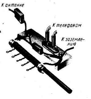 |
| Rice. 5 Receiver tuned with a ferrite rod. |
Remove the plate capacitor, and instead, between the antenna and ground terminals, i.e., parallel to the coil, turn on a mica or ceramic capacitor with a capacity of 120 - 150 pF. Press the phones closer to your ears, concentrate and very slowly insert the ferrite rod into the coil frame. Gradually deepening the rod into the coil, you should hear the transmissions of all those broadcasting stations that can be received in your area on a detector receiver. The longer the radio wave, the deeper the rod must be inserted into the coil. Empirically find such a position of the rod in the coil, at which the station signals are most loudly heard, and make a corresponding mark on the rod with a pencil. Using it as a division of the scale, you can quickly tune the receiver to the frequency of this station. Continuing the experiment using a ferrite rod, connect another capacitor in parallel with the coil with a capacity of 390 - 470 pF. How did this affect the tuning of the receiver? The volume remains the same, but to tune to the same station, the rod has to be inserted into the coil less. Remove the capacitor completely, leaving only the coil on. What happened? To tune the receiver to the same station, the rod must be inserted deeper into the coil. What conclusions can be drawn by conducting experiments with this version of the detector receiver? Main two. Firstly, a ferrite rod affects the inductance of the coil, and hence the tuning of the circuit, much more strongly than a metal object. Secondly, with the help of a ferrite rod, you can smoothly and accurately tune the receiver circuit to the desired radio station. Another experiment. Disconnect the antenna and ground from the receiver, turn on the diode between them, and in parallel - phones without a blocking capacitor. That's the whole receiver. Works? Quiet, perhaps? In addition, it is possible that the transmissions of two or three broadcasting stations are heard at the same time. You should not expect better from such a receiver. you probably noticed that when you touch parts or connecting conductors with your hand, the volume of the work changes slightly. This is due to the detuning of the antenna circuit, introduced into it by the electrical capacitance of your body.
Schematic diagram of the detector receiver
To correctly connect the parts of the receiver, you used the drawings. On them you saw a coil, telephones, a diode - a detector and other parts, devices and connections as they look in kind. This is very convenient for a start, while you have to deal with very simple radio engineering structures, consisting of a small number of parts. But if you try to depict the device of a modern receiver in this way, you would get such a “web” of parts and wires that would be impossible to understand. To avoid this, any electrical appliance or radio device is depicted schematically, i.e. using simplified drawing - diagrams . There are three main types of schemes: structural, basic electrical and wiring diagrams. A block diagram is a simplified drawing in which groups of parts and devices that perform certain functions of a radio engineering device are conventionally depicted with rectangles or other symbols. Structural diagram gives only general idea about the operation of this device, about its structure and the relationships between its functional groups. We can serve as an example of a block diagram (Fig. 2), according to which I told you about the principle of operation of a broadcasting station. Is it possible to depict the device of a detector receiver in this way? Of course you can. Draw four rectangles in one row and connect them with lines with arrows going from left to right. In the leftmost rectangle, enter the word "Antenna", in the next rectangle - "Oscillation circuit", in the third rectangle - "Detector", in the fourth - "Phones". Get a block diagram of the detector receiver. You can “read” it like this: modulated radio frequency oscillations excited in the antenna enter the receiver’s oscillatory circuit, and then to the detector, the detector extracts audio frequency oscillations from the received signal, which the phones convert into sound. Previously, such drawings were called skeletal diagrams or block diagrams . This terminology is now considered obsolete. fundamental wiring diagram often referred to as a principle or simply a diagram. On it, all the details of a radio engineering device and the order of their connection are depicted conventional signs, symbolizing these details, lines. "Reading" circuit diagram, like a geographical map or a drawing of some kind of mechanism, it is not difficult to understand the circuits and the principle of operation of the device. But it does not give an idea of the dimensions of the device and the placement of its parts on the circuit boards. The connection diagram, in contrast to the principle, informs how the parts of the device are located in the structure and interconnected. When assembling a receiver, amplifier or any other radio device, the radio amateur arranges the parts and conductors approximately as in the recommended wiring diagram. But the installation and all connections of parts are checked according to the circuit diagram of the device. Be able to correctly draw and read radio circuits - absolutely required condition for anyone who wants to become a radio amateur. In (Fig. 6) you see parts and devices already familiar to you and some others that you will have to deal with in the future. And next in the circles - their symbolic graphic images on the circuit diagrams.
Any coreless inductor, regardless of its design and number of turns, is depicted in a circuit diagram as a wavy line. The taps of the coils are shown by dashes. If the coil has a fixed ferromagnetic core (ferrite rod) that increases its inductance, it is indicated by a straight line along the image of the coil. If the receiver circuit is tuned with such a core, as it was in the experimental receiver, it is denoted in the diagram by the same straight line, but crossed with an arrow along with the coil. The tuning ferromagnetic core of the coil is indicated by a short bold line intersecting with a T - shaped symbol. Any capacitor of constant capacitance is depicted by two short parallel lines, symbolizing two plates isolated from one another. If the capacitor is electrolytic, its positive plate is denoted by an additional “+” sign. Capacitors of variable capacitance are depicted in the same way as capacitors of constant capacitance, but crossed obliquely by an arrow, symbolizing the variability of the capacitance of this device. Sockets for connecting the wire of the antenna, headphones or some other devices or parts are indicated by icons in the form of a plug, and the clamps are circles. New to you is the switch. Instead of twisting and twisting the conductors when setting up the receiver, as you did during experiments with a detector receiver, the leads and taps of the coil can be switched with a simple slider, slider, or other design switch. The conductors that connect the parts are indicated by straight lines. If the lines converge and there is a dot at the point of their intersection, then the conductors are connected. The absence of a dot at the intersection of the conductors indicates that they are not connected. On the schematic diagrams, next to the symbolic designations of radio components, devices, switching and other devices, the corresponding Latin letters are written. So, for example, all capacitors, regardless of their design features and applications, the letter C, resistors - the letter R, coils - the letter L, semiconductor diodes, transistors and many other semiconductor devices - the letter VD, V, antennas the letter W, sockets and other connecting devices - the letter X, headphones, loudspeaker heads , microphones and other converters of electrical or sound vibrations - the letter B, galvanic cells and batteries - the letter G, batteries of galvanic cells or batteries - the letters GB, incandescent lamps - the letter H, etc. In addition, on the diagrams, the parts are numbered, that is, next to the letter assigned to the part, a number is written, for example, Cl, L1, L2, R1, VI, etc. To simplify the circuit diagrams, they sometimes do not show an antenna, headphones, limited only to the designations of sockets or clamps for connecting them, but then they write the corresponding letters with numbers next to them: Wl, B1. More information about the conditional alphanumeric designation of radio engineering elements and devices on radio equipment diagrams can be found in the reference literature or on the Internet. Now, knowing the reference designations of parts, you can depict the detector receivers with which you experimented with schematic diagrams. The schematic diagram of the first version of the experimental receiver is shown in (Fig. 6, a). You tuned it by changing the number of coil sections included in the circuit by switching the grounded conductor. Therefore, the switch S1 is introduced into the circuit. Remember our "walk" through the receiver circuits and do it again, but according to the concept. From the beginning of the coil L1, indicated by a dot in the diagram, you will get to the diode VI and through it - telephones B1, then through the telephones along a grounded conductor. Switch S1 and coil turns Ll - to the starting point. This is a detector circuit. For high frequency currents, the path from the antenna to ground is through the coil sections and the switch. This is an antenna circuit. The receiver is tuned to the radio station by an abrupt change in the number of turns included in the circuit. A blocking capacitor C1 is connected in parallel to the telephones. In the diagram, the dashed lines show the capacitor Ca. There was no such detail in the receiver. But the electrical capacitance symbolizing it was present - it was formed by an antenna and grounding, and, as it were, connected to a customizable circuit. A schematic diagram of one of the subsequent variants of the experimental receiver is shown in (Fig. 6, b). Its input tuning circuit consists of a coil L1, which has one tap, a variable capacitor C2 you introduced, an antenna device and an antenna capacitor C1. The inclusion in the circuit of only the upper (according to the scheme) section of the coil corresponds to the reception of radio stations in the CB range, the inclusion of both sections corresponds to the reception of radio stations in the LW range. Thus, in the receiver, the transition from one range to another is carried out by switch S1, and smooth tuning in each range is carried out by a variable capacitor C2. The last option was a receiver tuned by a ferrite rod. You can see its schematic diagram in (Fig. 6, c). The oscillatory circuit is formed by a coil L1 and a capacitor of constant capacitance C2. The coil has no taps, which means that the receiver is single-range. To receive radio stations of another range, a coil must be included in the circuit, designed to receive stations of this range. B1 jacks are provided for connecting headphones.
Small-sized 5-element antenna of the "Wave channel" type(Fig. 10.23) is designed for installation in the reception area (see Fig. 10.1). The antenna can receive television signals in the channel groups indicated in Table. 10.17. The length of the carrier boom for all groups of channels is 660 mm. The distance D between the centers of the tubes of the active loop vibrator is 52...56 mm, the distance S between its ends is 26...30 mm. The diameter of the tubes for the manufacture of vibrators is 6...10 mm. Antenna elements are attached to the carrier boom in the form of a metal tube with a diameter of 20 ... 28 mm or to a wooden bar with a section of 20 x 20 mm.
Table 10.17
An active loop vibrator is connected to the feeder using a matching-balancing loop (see Fig. 10.13). Its length is calculated as the arithmetic mean for a given group of channels.
The gain of a small-sized 5-element antenna is 6.5 dB. KZD broadband antenna in both horizontal and vertical planes more than 20 dB.
11-element broadband antenna type "Wave channel" with a shortened carrying boom is shown in fig. 10.24, in table. 10.18 are her geometric dimensions for channel groups.
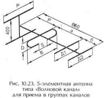
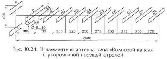
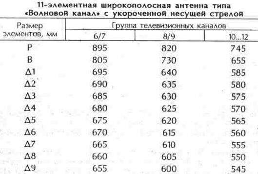
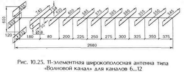
The distance between certain antenna elements is the same, so the carrier boom for all channel groups is 2680 mm. The high input impedance of the antenna is ensured by the proximity of the first director to the loop vibrator. Therefore, the antenna is connected to the feeder using a half-wave matching-balancing loop (see Fig. 10.13), the length of which is average for this combination of channels (see Table 10.1).
The antenna gain for each channel group is 10.5 dB. The opening angle of the main lobe of the radiation pattern in the horizontal plane must be at least 20 °, and in the vertical - at least 12 °. On fig. 10.25 shows the design of a broadband antenna of the "Wave channel" type for operation in the frequency band of channels 6 ... 12. The gain of such an antenna is 9 dB. The opening angles of the radiation pattern are the same as those of the antenna shown in Fig. 10.24.
Broadband fan vibrator. To expand the operating frequency band, a linear half-wave vibrator is made from a large diameter pipe. The disadvantage of "thick" vibrators is a significant weight, the complexity of fastening and installation. This can be avoided if, instead of such a pipe, several thin tubes are used, located in the same plane parallel to each other. Such vibrators are made of two cones facing each other. They are called biconical.
The simplest type of biconical vibrator is a fan vibrator (Fig. 10.26), each half of which consists of several tubes located in the same plane and diverging at some angle to each other. The fan vibrator operates in the frequency band 48.5 ... 100 and 174 ... 230 MHz, i.e. in all 12 channels of the VHF meter range. Alina of the vibrator is approximately l/2 at the average frequency of channels 1...5 and 3*l/2 at the average frequency of channels 6...12.
From fig. 10.26b it can be seen that the angle between the planes in which the vibrator tubes are located is 120° (inclination towards the television transmitter), and this is not accidental. The directivity pattern of a linear vibrator in the horizontal plane with a vibrator length equal to l/2 has the shape of a figure eight. In channels 6 ... 12 with a vibrator length of 3 * l / 2, the directivity pattern is distorted: the main lobe bifurcates and a dip appears in the direction of the television transmitter. To correct the radiation pattern, i.e., eliminate the dip, make the slope of the planes in which the tubes are located
vibrator. This not only eliminates the dip in the front lobe of the "eight", but also reduces the level of its rear lobe, as a result, the vibrator in channels 6...12 becomes more directional than in channels 1...5.
The field (voltage) gain of the broadband fan vibrator is 1 (0 dB) in channels 1...5 and 1.15 (1.3 dB) in channels 6...12. The length of the balancing short-circuited bridge is equal to l/4 at the average frequency of channels 1...5 and 3*l/4 in channels 6...12. [split]
Traveling wave antenna(ABV) is a directional antenna along the geometric axis of which the traveling wave of the received signal propagates. Usually ABV (Fig. 10.27) consists of a collecting line (1) and vibrators (2). The EMF induced by the electromagnetic field in the vibrators are added in the collecting line in phase and enter the feeder. Unlike antennas of the "Wave Channel" type, ABV
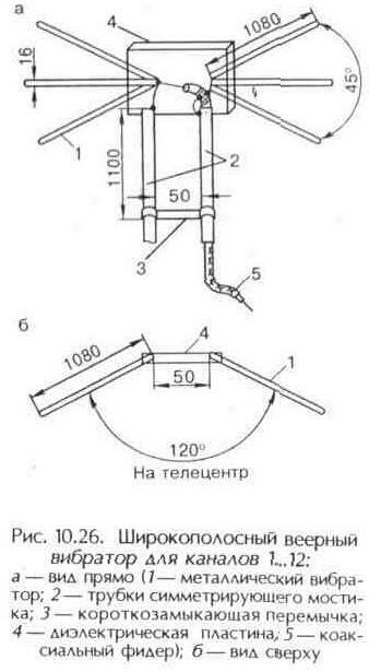
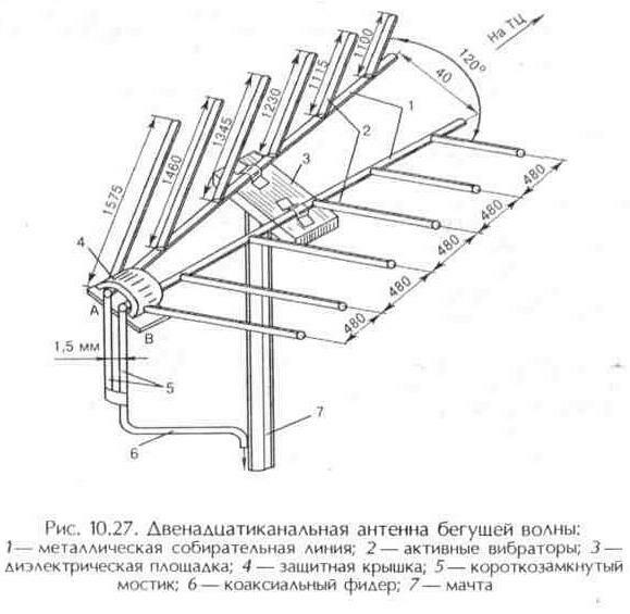
all vibrators are active, broadband and do not need to be tuned.
The collecting line ABV is formed by two tubes with a diameter of 22 ... 30 mm, diverging at a slight angle. It is a two-wire line of variable impedance. Six tubes (vibrators) of the same diameter, bent at an angle of 120°, are connected to each tube of the collecting line at an angle of 60° at the same distance from each other. Such vibrators provide a significant reduction in the rear lobe of the antenna pattern, due to which, in most of the operating range of the antenna, the SAR of the antenna is at least 14 dB. The tubes of the collecting line are fastened together by plates of insulating material located at the top and bottom. The middle plate is used to fix the antenna on the mast at the center of gravity.
The feeder is connected to the antenna using a short-circuited bridge, which is formed by two metal tubes (5) with a metal jumper at the bottom. Feeder with
with a wave resistance of 750 m enters the bridge tube, which is located on the right. A transformer from a cable with a characteristic impedance of 50 Ohms is connected to its end (the length of the transformer is 700 ... 750 mm). The other end of the cable runs through upper end right tube. Here the cable braid is soldered to the right tube of the bridge, and the central conductor to the left. Alina bridge (1100 mm) and transformer (700...750 mm) is chosen so that in the range of channels 1...5 it corresponds to about 1/4 of the average wavelength, and for channels 6...12 - 3/4 of the average wavelength. This provides an acceptable antenna-to-feeder match. On
In practice, sometimes they do without a matching device (for short-range reception). In these cases, a balancing loop is used from segments of a coaxial cable (see Fig. 10.12). Points A and B of the bridge can be protected by a cover (4). The gain of the traveling wave antenna in channels 1 and 2 is 3.5 dB, in 3...5 - 4.6, in channels 6...12 - 8 dB.
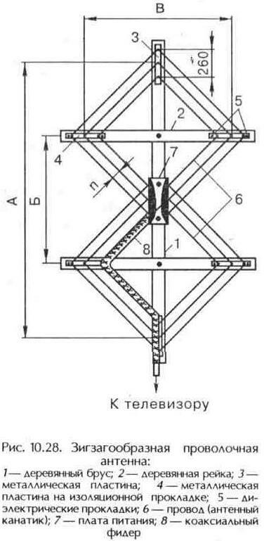
Table 10.19
![]()
Zigzag meter wave antenna. The design of the antenna is relatively simple and deviations in one direction or another from the nominal dimensions, which are inevitable during its manufacture, practically do not affect the parameters. As a television zigzag antenna (Fig. 10.28;
tab. 10.19) can be made to work in channels 1...5 (50...100 MHz) or 6...12 (174...230 MHz).
Zigzag antenna device. Two horizontal rails (2) with a cross section of 40 x 40 mm are attached to a wooden block (1) with a section of approximately 60 x 60 mm at an angle of 90 °. Two metal plates are attached to the ends of the bar
(3), to the ends of the rails - the same metal plates
(4), but through dielectric spacers (5). The power board (7) consists of two metal plates assembled on an insulating pad. The thickness of the material of the plates and their dimensions are chosen arbitrarily, but the distance between the plates should be 10 ... 15 mm for channels 1 ... 5 and 7 ... 10 mm for channels 6 ... 12. An antenna fabric is pulled onto the prepared structure from three parallel wires (6) with a diameter of 2 ... 3 mm or from an antenna cord. In places of inflection, the wires are soldered to the plates (3), (4), (7).
Feeder (8) from a coaxial cable with a wave impedance of 75 Ohm is laid along one of the internal wires of the antenna web to the power board. The cable braid is soldered to the plate (7). The center conductor of the cable is soldered to the opposite plate (3). Additional matching-balancing devices are not needed when connecting the feeder to a zigzag antenna. The bottom plate (3) can be earthed if necessary, as it is the zero potential point.
The zigzag antenna has two identical lobes of the radiation pattern in the horizontal plane, the maxima of which are oriented perpendicular to the plane of the antenna web. Thus, these antennas receive signals from the front and back, like a linear or looped half-wave vibrator, which creates a danger
receive interference from the opposite direction. Significantly improve the work / zigzag antenna can be due to its complication using a reflector (Fig. 10.29). The reflector is formed by horizontal conductors, which are fixed on a wooden or metal frame. The antenna sheet is moved away from the plane of the reflector by a certain distance E (Table 10.19).
The radiation pattern of this antenna has one main lobe, and there is practically no rear lobe. The presence of a reflector increases the gain by 1.5...2 times. In channels 1 ... 5, the gain of the zigzag antenna smoothly increases from 7.8 dB in the first channel to 14 dB in the fifth, and in channels 6 ... 12 - from 7.8 to 10 dB.