electric oscillatory circuit called a closed circuit consisting of a capacitor WITH and inductors L(Fig. 9.8). Periodically repeating changes in the current strength in the coil and the voltage across the capacitor in the absence of external influences are called free vibrations.
When connected to the plates of a charged capacitor (Fig. 9.8 A) of an inductor, a current appears in it. If the electrical resistance of the coil is negligible, then the energy of the electric field W e charged capacitor begins to turn into energy magnetic field W m. The instantaneous discharging of the capacitor is prevented by the self-induction EMF, which restrains the process of increasing the current strength in the coil.
At the moment when the capacitor is completely discharged, the current in the coil and the energy of the magnetic field will reach maximum (amplitude) values (Fig. 9.8 b). After the capacitor is discharged, the current in the coil decreases, but this leads to a decrease in the magnetic flux, which causes the appearance of self-induction and induction current in the EMF coil. Now the direction of the induction current is such that it prevents the decrease in the magnetic flux.
The capacitor is charged by the inductive current of the coil. When the current disappears, the capacitor will be charged to its original charge value, but of the opposite sign (Fig. 9.8 V). After this happens next process recharging the capacitor with current flowing in the opposite direction (Fig. 9.8 G), and return to its original state after one complete oscillation (Fig. 9.8 d). The upper part of the figure shows the time values of the corresponding states, expressed in fractions of the period
Where w 0- circular (cyclic) frequency of oscillations in the circuit.
From the law of conservation of energy it follows that in the absence of resistance in the circuit, the maximum energy value We electric field of a charged capacitor is equal to the maximum value of the energy of the magnetic field W m coils: , from where you can get the relationship between the amplitude values of the current in the coil and the voltage across the capacitor: . This ratio has the dimension of resistance, so the quantity is called wave, or characteristic loop resistance.
Real electrical circuit due to energy losses for heating conductors and dielectrics, the energy of the magnetic and electric fields is gradually converted into internal energy. Free electromagnetic oscillations in the circuit are fading .
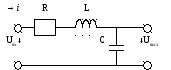
Energy losses in the circuit can be taken into account by introducing active resistance (Fig. 9.9). Since the losses in the dielectric of the capacitor are small, this resistance is almost equal to active resistance inductors. Considering the direction of the current charging the capacitor as positive, we write Ohm's law for the circuit section from the negatively charged capacitor plate 1
to positively charged 2
. In accordance with (2.13) we get: ![]() .
.
Direction of contour traversal from point 1 to the point 2 coincides with the direction of the current, so the product iR positively. EMF of self-induction according to Lenz's rule is negative. Since the potential of the negatively charged plate is less than the potential of the positive one, the potential difference (j 1 - j 2) negative: where q is the charge on the capacitor. The change in the charge of the capacitor is caused by current, therefore. In view of the foregoing, on the basis of Ohm's law, we can write:
![]() , or
, or
![]() , (9.8)
, (9.8)
Where b = R/2L- attenuation coefficient, - natural frequency.
The differential equation (9.8) is similar to the equation obtained for a mechanical spring pendulum (see section "Mechanics"). The solution to this equation has the form: ![]() , (9.9)
, (9.9)
Where q0- amplitude of the current at the initial moment of time,
Frequency of damped oscillations. From (9.9) it follows that the decrease in amplitude over time occurs according to an exponential law (Fig. 9.10). The frequency of damped oscillations is less than the frequency of natural oscillations w 0. From (9.10) it follows that for large damping (b ³ w 0) the frequency becomes an imaginary quantity. This means that the oscillatory process does not occur and the charge of the capacitor decreases to zero without recharging. Such a process is called aperiodic .
Let us express the condition for the transition from an oscillatory process to an aperiodic one in terms of the circuit parameters. We have: (R/2L) 2³ 1/LC or .
It is customary to characterize the degree of damping of oscillations logarithmic damping decrement . It is equal to the natural logarithm of two amplitudes through the period T:
![]() or (9.11)
or (9.11)
Another feature of the circuit is quality factor. It is related to the logarithmic damping decrement by the relation . It is easy to show that at low damping, when b<< w 0 And w" » w 0 , the quality factor is expressed through the parameters of the oscillatory circuit as follows: , (9.12)
that is, it is equal to the ratio of the characteristic resistance of the circuit to the active resistance of the losses.
Oscillatory circuit is called ideal if it consists of a coil and a capacitance and there is no loss resistance in it.
Consider the physical processes in the following chain:
1 The key is in position 1. The capacitor begins to charge, from the voltage source and the energy of the electric field accumulates in it,
i.e. the capacitor becomes a source of electrical energy.
2. Key in position 2. The capacitor will begin to discharge. The electrical energy stored in the capacitor is converted into the energy of the magnetic field of the coil.
The current in the circuit reaches its maximum value (point 1). The voltage on the capacitor plates decreases to zero.

In the period from point 1 to point 2, the current in the circuit decreases to zero, but as soon as it starts to decrease, the magnetic field of the coil decreases and the self-induction EMF is induced in the coil, which counteracts the decrease in current, so it decreases to zero not abruptly, but smoothly. Since an EMF of self-induction arises, the coil becomes a source of energy. From this EMF, the capacitor begins to charge, but with reverse polarity (the capacitor voltage is negative) (at point 2, the capacitor is charged again).
Conclusion: in an LC circuit there is a continuous oscillation of energy between electric and magnetic fields, therefore such a circuit is called an oscillatory circuit.
The resulting vibrations are called free or own, since they occur without the help of an external source of electrical energy introduced earlier into the circuit (into the electric field of the capacitor). Since the capacitance and inductance are ideal (there is no loss resistance) and the energy does not leave the circuit, the oscillation amplitude does not change over time and the oscillations will undamped.
Let us determine the angular frequency of free oscillations:
We use the equality of the energies of the electric and magnetic fields
![]()
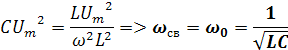
Where ώ is the angular frequency of free oscillations.
[ ώ ]=1/s
f0= ώ /2π [Hz].
Period of free oscillations T0=1/f.
The frequency of free vibrations is called the natural frequency of the circuit.
From the expression: ώ²LC=1 we get ώL=1/Cώ, therefore, at a current in a circuit with a frequency of free oscillations, the inductive reactance is equal to the capacitance.
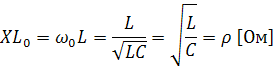

Characteristic resistances.
Inductive or capacitive resistance in an oscillatory circuit at a frequency of free oscillations is called characteristic resistance.
The characteristic resistance is calculated by the formulas:
5.2 Real oscillating circuit
A real oscillatory circuit has active resistance, therefore, when exposed to free oscillations in the circuit, the energy of a pre-charged capacitor is gradually spent, being converted into heat.
Free oscillations in the circuit are damped, since in each period the energy decreases and the amplitude of the oscillations in each period will decrease.
![]()
The figure is a real oscillatory circuit.
Angular frequency of free oscillations in a real oscillatory circuit:
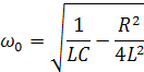
If R=2…, then the angular frequency is equal to zero, therefore free oscillations will not occur in the circuit.
Thus oscillatory circuit called an electrical circuit consisting of inductance and capacitance and having a small active resistance, less than twice the characteristic resistance, which ensures the exchange of energy between inductance and capacitance.
In a real oscillatory circuit, free oscillations damp out the faster, the greater the active resistance.
To characterize the damping intensity of free oscillations, the concept of "loop damping" is used - the ratio of active resistance to characteristic.

In practice, the reciprocal of attenuation is used - the quality factor of the circuit.
![]()
To obtain undamped oscillations in a real oscillatory circuit, it is necessary during each oscillation period to replenish electrical energy at the active resistance of the circuit in time with the frequency of natural oscillations. This is done with a generator.
If you connect the oscillatory circuit to an alternator whose frequency differs from the frequency of free oscillations of the circuit, then a current flows in the circuit with a frequency equal to the frequency of the generator voltage. These oscillations are called forced.
If the frequency of the generator differs from the natural frequency of the circuit, then such an oscillatory circuit is untuned relative to the frequency of the external influence, but if the frequencies are the same, then it is tuned.
Task: Determine the inductance, the angular frequency of the circuit, the characteristic resistance, if the capacitance of the oscillatory circuit is 100 pF, the frequency of free oscillations is 1.59 MHz.
Solution:
Test tasks:
Lesson Topic 8: VOLTAGE RESONANCE
Voltage resonance is the phenomenon of increasing voltages on reactive elements that exceed the voltage at the circuit terminals at the maximum current in the circuit, which is in phase with the input voltage.
Resonance conditions:
Serial connection of L and C with an alternator;
The frequency of the generator must be equal to the frequency of natural oscillations of the circuit, while the characteristic impedances are equal;
The resistance must be less than 2ρ, since only in this case free oscillations will appear in the circuit, supported by an external source.
Circuit impedance:
since the characteristic resistances are equal. Therefore, at resonance, the circuit is purely active, which means that the input voltage and current at the time of resonance are in phase. The current takes on a maximum value.
![]()
At the maximum current value, the voltage in sections L and C will be large and equal to each other.
Voltage at the circuit terminals:
Consider the following relations:
![]() , hence
, hence
Q – the quality factor of the circuit - at voltage resonance, it shows how many times the voltage on the reactive elements is greater than the input voltage of the generator supplying the circuit. At resonance, the transfer coefficient of a series resonant circuit
resonance.
![]()
Example:
Uc=Ul=QU=100V,
that is, the voltage across the terminals is less than the voltages across the capacitance and inductance. This phenomenon is called voltage resonance.
At resonance, the transfer coefficient is equal to the quality factor.
Let's build a vector voltage diagram
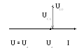
The voltage across the capacitance is equal to the voltage across the inductor, so the voltage across the resistance is equal to the voltage across the terminals and is in phase with the current.
Consider the energy process in the oscillatory circuit:
In the circuit there is an exchange of energy between the electric field of the capacitor and the magnetic field of the coil. The coil energy is not returned to the generator. From the generator, the circuit receives such an amount of energy that is spent on the resistor. This is necessary so that undamped oscillations are observed in the circuit. The power in the circuit is only active.
Let's prove it mathematically:
![]() , the apparent power of the circuit, which is equal to the active power.
, the apparent power of the circuit, which is equal to the active power.
reactive power.
8.1 Resonant frequency. Detuning.
Lώ=l/ώC, hence
![]()
![]() , angular resonant frequency.
, angular resonant frequency.
It can be seen from the formula that resonance occurs if the frequency of the supply generator is equal to the natural oscillations of the circuit.
When working with an oscillatory circuit, it is necessary to know whether the frequency of the generator and the natural frequency of the circuit coincide. If the frequencies match, then the circuit remains tuned to resonance, if it does not match, then there is a detuning in the circuit.
There are three ways to tune the oscillatory circuit to resonance:
1 Change the frequency of the generator, with the values of capacitance and inductance const, that is, by changing the frequency of the generator, we adjust this frequency to the frequency of the oscillatory circuit
2 Change the inductance of the coil, at a power frequency and capacitance const;
3 Change the capacitance of the capacitor, with a supply frequency and inductance const.
In the second and third methods, by changing the frequency of natural oscillations of the circuit, we adjust it to the frequency of the generator.
With an untuned circuit, the frequency of the generator and the circuit are not equal, that is, there is a detuning.
Detuning - frequency deviation from the resonant frequency.
There are three types of disruption:
Absolute - the difference between a given frequency and resonant
![]()
Generalized - the ratio of reactance to active:
![]()
Relative - the ratio of the absolute detuning to the resonant frequency:
![]()
At resonance, all detunings are zero , if the generator frequency is less than the circuit frequency, then the detuning is considered negative,
If more - positive.
Thus, the quality factor characterizes the quality of the circuit, and the generalized detuning characterizes the distance from the resonant frequency.
8.2 Building dependencies X, X L , X C from f.
Tasks:
Loop resistance 15 ohm, inductance 636 μH, capacitance 600 pF, mains voltage 1.8 V. Find the loop natural frequency, loop attenuation, characteristic impedance, current, active power, quality factor, voltage at the loop terminals.
Solution:
The voltage at the generator terminals is 1 V, the mains frequency is 1 MHz, the quality factor is 100, the capacitance is 100 pF. Find: attenuation, characteristic impedance, resistance, inductance, circuit frequency, current, power, capacitance and inductance voltages.
Solution:
Test tasks:
Topic 9 : Input and transfer frequency response and phase response of a series oscillatory circuit.
9.1 Input frequency response and phase response.

In a series oscillatory circuit:
R - active resistance;
X - reactance.
"Harmonic vibrations"- They are called. 1. Is the phase difference zero or an even number?, that is. Figure 4. Topic 2 ADDITION OF HARMONIC OSCILLATIONS. 2.3 Addition of mutually perpendicular oscillations. The beat method is used for tuning musical instruments, hearing analysis, etc. Figure 5. Then. ?1 is the phase of the 1st oscillation. - The resulting oscillation, also harmonic, with a frequency?:
"Frequency of Oscillation"- Infrasound. What are the common properties of all sound sources? What determines the pitch of a sound? Recall everything we know about sound. Each of us is familiar with such a sound phenomenon as an echo. What is pure tone? Project content: The sound of a tuning fork is a pure tone. Prepared by a 9th grade student: Ekaterina Smolyaninova.
"Physics of Oscillations and Waves"- Be able to: Calculate the period and frequency of oscillation of the pendulum, the acceleration of free fall using a mathematical pendulum, the wavelength. Generalization of the topic Literature for work: 1. Physics-9 - textbook 2. Physics-8. author Gromov 3. Physics, man, environment. (appendix to the textbook). After studying the topic. Waves and waves, you must ...
"Free Vibrations"- Thompson formula. If Um = const, then the amplitude of the forced oscillations of the current strength depends on? : Magnetic flux Ф through the plane of the frame: Where i and q are the current strength and electric charge at any time. Fig.1. Cyclic frequency of free electromagnetic oscillations in the circuit: From Ohm's law for the section of the alternating current circuit:
"Mechanical Vibrations"- Forced. Forced vibrations. Waves. Completed by: student of grade 11 "A" Oleinikova Julia. Transverse. Harmonic vibrations. Free. Elastic waves are mechanical disturbances propagating in an elastic medium. Mechanical oscillations and waves. Oscillations are movements or processes that are characterized by a certain repetition in time.
"Resonance"- Due to the huge mass and inertia, the liquid reacts to concussions with a delay. Acoustic resonance - a tube with water and a tuning fork without a resonator. It is very important to correctly install and configure all system components. The beating of the heart, the contraction of the stomach, the activity of the intestines are oscillatory.
There are 10 presentations in total in the topic
>> An equation describing the processes in an oscillatory circuit. Period of free electrical oscillations
§ 30 EQUATION DESCRIBING PROCESSES IN THE OSCILLATORY CIRCUIT. PERIOD OF FREE ELECTRIC OSCILLATIONS
Let us now turn to the quantitative theory of processes in an oscillatory circuit.
An equation describing the processes in an oscillatory circuit. Consider an oscillatory circuit, the resistance R of which can be neglected (Fig. 4.6).
The equation describing the free electrical oscillations in the circuit can be obtained using the law of conservation of energy. The total electromagnetic energy W of the circuit at any time is equal to the sum of its energies of the magnetic and electric fields:
![]()
This energy does not change over time if its resistance R of the circuit is zero. Hence, the time derivative of the total energy is zero. Therefore, the sum of the time derivatives of the energies of the magnetic and electric fields is equal to zero:
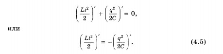
The physical meaning of equation (4.5) is that the rate of change in the energy of the magnetic field is equal in absolute value to the rate of change in the energy of the electric field; the "-" sign indicates that as the energy of the electric field increases, the energy of the magnetic field decreases (and vice versa).
Calculating the derivatives in equation (4.5), we get 1
But the time derivative of the charge is the current strength at a given time:
Therefore, equation (4.6) can be rewritten in the following form:
1 We calculate derivatives with respect to time. Therefore, the derivative (і 2) "is not just equal to 2 i, as it would be when calculating the derivative but i. It is necessary to multiply 2 i by the derivative i" of the current strength with respect to time, since the derivative of a complex function is calculated. The same applies to the derivative (q 2)".
The derivative of the current with respect to time is nothing but the second derivative of the charge with respect to time, just as the derivative of velocity with respect to time (acceleration) is the second derivative of the coordinate with respect to time. Substituting into equation (4.8) i "= q" and dividing the left and right parts of this equation by Li, we obtain the main equation describing free electrical oscillations in the circuit:
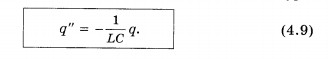
Now you can fully appreciate the significance of the efforts that have been expended to study the oscillations of a ball on a spring and a mathematical pendulum. After all, equation (4.9) does not differ in anything, except for the notation, from equation (3.11), which describes the vibrations of a ball on a spring. Replacing x with q, x" with q", k with 1/C, and m with L in equation (3.11), we obtain equation (4.9) exactly. But equation (3.11) has already been solved above. Therefore, knowing the formula describing the oscillations of a spring pendulum, we can immediately write down a formula for describing the electrical oscillations in the circuit.
Lesson content lesson summary support frame lesson presentation accelerative methods interactive technologies Practice tasks and exercises self-examination workshops, trainings, cases, quests homework discussion questions rhetorical questions from students Illustrations audio, video clips and multimedia photographs, pictures graphics, tables, schemes humor, anecdotes, jokes, comics parables, sayings, crossword puzzles, quotes Add-ons abstracts articles chips for inquisitive cheat sheets textbooks basic and additional glossary of terms other Improving textbooks and lessonscorrecting errors in the textbook updating a fragment in the textbook elements of innovation in the lesson replacing obsolete knowledge with new ones Only for teachers perfect lessons calendar plan for the year methodological recommendations of the discussion program Integrated Lessons


