ELECTROMAGNETIC OSCILLATIONS.
FREE AND FORCED ELECTRIC OSCILLATIONS.
Electromagnetic vibrations- interconnected fluctuations of electric and magnetic fields.
Electromagnetic oscillations appear in various electrical circuits. In this case, the magnitude of the charge, voltage, current strength, electric field strength, induction fluctuate magnetic field and other electrodynamic quantities.
Free electromagnetic oscillations occur in electromagnetic system after removing it from the state of equilibrium, for example, by charging the capacitor or changing the current in the circuit section.
These are damped oscillations, since the energy communicated to the system is spent on heating and other processes.
Forced electromagnetic oscillations - undamped oscillations in the circuit caused by an external periodically changing sinusoidal EMF.
Electromagnetic oscillations are described by the same laws as mechanical ones, although the physical nature of these oscillations is completely different.
Electrical oscillations are a special case of electromagnetic ones, when oscillations of only electrical quantities are considered. In this case, they talk about alternating current, voltage, power, etc.
OSCILLATORY CIRCUIT
An oscillating circuit is an electrical circuit consisting of a capacitor with a capacitance C, an inductor with an inductance L and a resistor with a resistance R connected in series.

The state of stable equilibrium of the oscillatory circuit is characterized by the minimum energy of the electric field (the capacitor is not charged) and the magnetic field (there is no current through the coil).
Quantities expressing the properties of the system itself (system parameters): L and m, 1/C and k
quantities characterizing the state of the system:
quantities expressing the rate of change in the state of the system: u = x"(t) And i = q"(t).
CHARACTERISTICS OF ELECTROMAGNETIC OSCILLATIONS
It can be shown that the equation of free vibrations for a charge q = q(t) capacitor in the circuit has the form
Where q" is the second derivative of charge with respect to time. Value
is the cyclic frequency. The same equations describe fluctuations in current, voltage, and other electrical and magnetic quantities.
One of the solutions to equation (1) is the harmonic function
The oscillation period in the circuit is given by the formula (Thomson):
![]()
The value φ \u003d ώt + φ 0, which is under the sign of sine or cosine, is the phase of the oscillation.
The phase determines the state of the oscillating system at any time t.
The current in the circuit is equal to the derivative of the charge with respect to time, it can be expressed
To more clearly express the phase shift, let's move from cosine to sine
AC ELECTRIC CURRENT
1. Harmonic EMF occurs, for example, in a frame that rotates with a constant angular velocity in a uniform magnetic field with induction B. Magnetic flux F, penetrating the frame with the area S,
where is the angle between the normal to the frame and the magnetic induction vector.
According to Faraday's law of electromagnetic induction, the EMF of induction is equal to
where is the rate of change of the flux of magnetic induction.
A harmonically varying magnetic flux induces a sinusoidal induction EMF
where is the amplitude value of the induction emf.
2. If you connect a source of external harmonic EMF to the circuit
then forced oscillations occur in it, occurring with a cyclic frequency ώ coinciding with the frequency of the source.
In this case, the forced oscillations make a charge q, the potential difference u, current strength i and other physical quantities. These are undamped oscillations, since energy is supplied to the circuit from a source, which compensates for losses. Harmoniously changing current, voltage and other quantities in the circuit are called variables. They obviously vary in size and direction. Currents and voltages that vary only in magnitude are called pulsating.
In industrial AC circuits in Russia, a frequency of 50 Hz is adopted.
To calculate the amount of heat Q released when an alternating current passes through a conductor with active resistance R, the maximum power value cannot be used, since it is reached only at certain points in time. It is necessary to use the average power for the period - the ratio of the total energy W entering the circuit for the period to the value of the period:
![]()
Therefore, the amount of heat released during the time T:
The effective value I of the alternating current is equal to the strength of such direct current, which, in a time equal to the period T, releases the same amount of heat as alternating current:
Hence the effective value of the current
Similarly effective voltage value
TRANSFORMER
Transformer- a device that increases or decreases the voltage several times with virtually no energy loss.
The transformer consists of a steel core assembled from separate plates, on which two coils with wire windings are mounted. The primary winding is connected to an alternating voltage source, and devices that consume electricity are connected to the secondary.
the value
![]()
called the transformation ratio. For step-down transformer K> 1, for step-up K< 1.
Example. The charge on the plates of the capacitor of the oscillatory circuit changes over time in accordance with the equation. Find the period and frequency of oscillations in the circuit, the cyclic frequency, the amplitude of charge oscillations and the amplitude of current oscillations. Write the equation i = i(t) expressing the dependence of the current strength on time.

It follows from the equation that . The period is determined by the cyclic frequency formula
![]()
Oscillation frequency
![]()
The dependence of the current strength on time has the form:
Current amplitude.
Answer: the charge oscillates with a period of 0.02 s and a frequency of 50 Hz, which corresponds to a cyclic frequency of 100 rad / s, the amplitude of current oscillations is 510 3 A, the current changes according to the law:
i=-5000sin100t
Tasks and tests on the topic "Topic 10. "Electromagnetic oscillations and waves.""
- oscillatory movement. Free vibrations. Amplitude, frequency, oscillation period - Mechanical oscillations and waves. Sound grade 9
In electrical circuits, as well as in mechanical systems, such as a weight on a spring or a pendulum, there may be free vibrations.
Electromagnetic vibrationscalled periodic interrelated changes in charge, current and voltage.
Freeoscillations are called those that occur without external influence due to the initially accumulated energy.
compelledare called oscillations in the circuit under the action of an external periodic electromotive force
Free electromagnetic oscillations are periodically repeating changes in electromagnetic quantities (q- electric charge,I- current strength,U- potential difference) occurring without energy consumption from external sources.
Protozoa electrical system, capable of performing free oscillations, is serial RLC loop or oscillatory circuit.
Oscillatory circuit -is a system consisting of series-connected capacitance capacitorsC, inductorsL and a conductor with resistanceR
Consider a closed oscillatory circuit consisting of an inductance L and containers WITH.
To excite oscillations in this circuit, it is necessary to inform the capacitor of a certain charge from the source ε . When the key K is in position 1, the capacitor is charged to voltage. After switching the key to position 2, the process of discharging the capacitor through the resistor begins R and an inductor L. Under certain conditions, this process can be oscillatory.

Free electromagnetic oscillations can be observed on the oscilloscope screen.
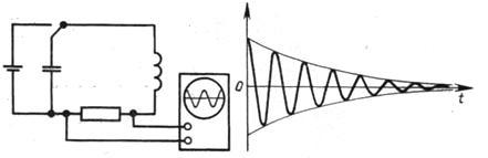
As can be seen from the oscillation graph obtained on the oscilloscope, free electromagnetic oscillations are fading, i.e., their amplitude decreases with time. This is because some of the electrical energy active resistance R is converted into internal energy. conductor (the conductor heats up when passing through it electric current).
Let's look at how fluctuations occur in oscillatory circuit and what energy changes take place. Let us first consider the case when there are no losses of electromagnetic energy in the circuit ( R = 0).
If you charge the capacitor to a voltage U 0, then at the initial time t 1 =0, the amplitude values of the voltage U 0 and charge q 0 = CU 0 will be established on the capacitor plates.
The total energy W of the system is equal to the energy of the electric field W el:
![]()
If the circuit is closed, then current begins to flow. Emf appears in the circuit. self-induction
Due to self-induction in the coil, the capacitor is not discharged instantly, but gradually (since, according to the Lenz rule, the resulting inductive current with its magnetic field counteracts the change in the magnetic flux by which it is caused. That is, the magnetic field of the inductive current does not allow the magnetic flux of the current to instantly increase in the contour). In this case, the current increases gradually, reaching its maximum value I 0 at time t 2 =T/4, and the charge on the capacitor becomes equal to zero.
As the capacitor discharges, the energy of the electric field decreases, but at the same time the energy of the magnetic field increases. The total energy of the circuit after discharging the capacitor is equal to the energy of the magnetic field W m:
At the next moment in time, the current flows in the same direction, decreasing to zero, which causes the capacitor to recharge. The current does not stop instantly after the capacitor is discharged due to self-induction (now the magnetic field of the induction current does not allow the magnetic flux of the current in the circuit to decrease instantly). At the time t 3 \u003d T / 2, the capacitor charge is again maximum and equal to the initial charge q \u003d q 0, the voltage is also equal to the initial U \u003d U 0, and the current in the circuit is zero I \u003d 0.
Then the capacitor discharges again, the current flows through the inductor in the opposite direction. After a period of time T, the system returns to its initial state. Complete oscillation is completed, the process is repeated.
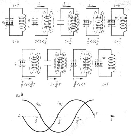
The graph of change in charge and current strength with free electromagnetic oscillations in the circuit shows that the current strength fluctuations lag behind the charge fluctuations by π/2.
At any given time, the total energy is:
![]()
With free vibrations, a periodic transformation of electrical energy occurs W e, stored in the capacitor, into magnetic energy W m coil and vice versa. If there are no energy losses in the oscillatory circuit, then the total electromagnetic energy of the system remains constant.
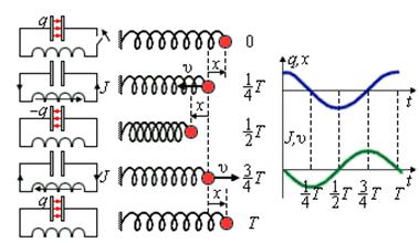
Free electrical vibrations are similar to mechanical vibrations. The figure shows graphs of charge change q(t) capacitor and bias x(t) load from the equilibrium position, as well as current graphs I(t) and load speed υ( t) for one period of oscillation.
In the absence of damping, free oscillations in an electrical circuit are harmonic, that is, they occur according to the law
q(t) = q 0 cos(ω t + φ 0)
Options L And C oscillatory circuit determine only the natural frequency of free oscillations and the period of oscillations - Thompson's formula
Amplitude q 0 and initial phase φ 0 are determined initial conditions, that is, the way in which the system was brought out of equilibrium.
For fluctuations in charge, voltage and current, formulas are obtained:
For a capacitor:
q(t) = q 0 cosω 0 t
U(t) = U 0 cosω 0 t
For an inductor:
i(t) = I 0 cos(ω 0 t+ π/2)
U(t) = U 0 cos(ω 0 t + π)
Let's remember main characteristics of oscillatory motion:
q 0, U 0 , I 0 - amplitude is the modulus of the largest value of the fluctuating quantity
T - period- the minimum time interval after which the process is completely repeated
ν - Frequency- the number of oscillations per unit time
ω - Cyclic frequency is the number of oscillations in 2n seconds
φ - oscillation phase- the value standing under the cosine (sine) sign and characterizing the state of the system at any time.
The discovery of radio waves has given humanity a lot of opportunities. Among them: radio, television, radar, radio telescopes and wireless communications. All this made life easier for us. With the help of the radio, people can always ask for help from rescuers, ships and planes can send a distress signal, and you can find out what is happening in the world.
The hypothesis of the existence of radio waves was put forward by the English scientist James Maxwell on the basis of a study of Faraday's work on electricity. To hypothesize about the possibility of electromagnetic waves Maxwell had the following reasons. Discovery of the induced current by Faraday. Maxwell explained the appearance of an induction current by the appearance of an eddy electric field with any change in the magnetic field. He further proposed that the electric field has the same properties: with any change in the electric field in the surrounding space, a vortex electric field arises.
Once begun, the process of mutual generation of magnetic and electric fields must continue uninterruptedly and capture the Radio Wave Scheme.
more and more new areas in the surrounding space. The process of mutual generation of electric and magnetic fields occurs in mutually perpendicular planes. Electric and magnetic fields can exist in matter and in a vacuum, and can propagate in a vacuum. The condition for the emergence of electromagnetic waves is the accelerated movement of electric charges. So, a change in the magnetic field occurs when the current in the conductor changes, and a change in current occurs when the speed of the charges changes. Therefore, electromagnetic waves should arise during the accelerated movement of electromagnetic charges.
But the creation of electromagnetic waves empirically belongs to the physicist Hertz. For this, Hertz used a high-frequency spark gap (Vibrator). This experiment was carried out by Hertz in 1888. The vibrator consisted of two rods separated by a spark gap. Hertz experimented with waves with a frequency of 100,000,000 Hz. Having calculated the natural frequency of the electromagnetic oscillations of the vibrator, Hertz was able to determine the speed of the electromagnetic wave using the formula υ=λν. It turned out to be approximately equal to the speed of light: c=300,000 km/s. Hertz's experience brilliantly confirmed Maxwell's predictions. To excite oscillations, the vibrator was connected to an inductor. When 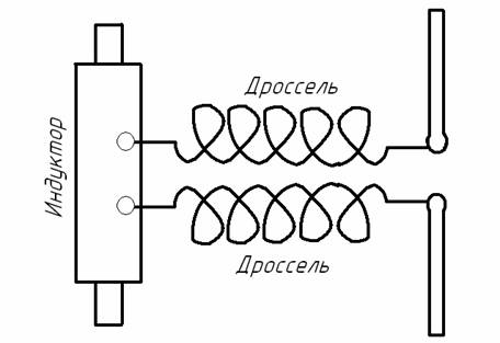 the voltage across the spark gap reached a breakdown value, a spark arose, which short-circuited both halves of the vibrator. As a result, free damped oscillations arose, which continued until the spark was extinguished. And in order to prevent the high-frequency current arising from oscillations from branching into the inductor winding, chokes (coils with high inductance) were switched on between the vibrator and the inductor. After the spark went out, the vibrator was again charged from the inductor, and the whole process was repeated again. Thus, the Hertz vibrator excited a series of trains of weakly damped waves.
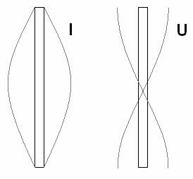 And during these oscillations, a standing wave of current and voltage was established. The current strength I was maximum (antinode) in the middle of the vibrator and vanished at its ends. Voltage U in the middle of the vibrator had a node, at the ends - antinodes. Hertz's experiments were continued by P.N. Lebedev in 1894. P.N. Lebedev discovered double refraction of waves in a crystal. Also, radio waves have all the basic properties of waves.
Electromagnetic waves depending on the wavelength (or oscillation frequency) are conditionally divided into the following main ranges: radio waves, infrared waves, x-rays, visible spectrum, ultraviolet waves and gamma rays. Such a division of electromagnetic waves is based on the difference in their properties during radiation, propagation and interaction with matter.
Despite the fact that the properties of electromagnetic waves of different ranges can differ sharply from each other, they all have a single wave nature and are described by the system of Maxwell's equations. The quantities and in an electromagnetic wave in the simplest case vary according to a harmonic law. The equations for a plane electromagnetic wave propagating in the Z direction are:
where is the cyclic frequency, n is the frequency, is the wave number, is the initial phase of the oscillations.
Electromagnetic waves are transverse waves, i.e. fluctuations of the intensity vectors of the alternating electric and induction of the alternating magnetic field are mutually perpendicular and lie in a plane perpendicular to the wave propagation velocity vector. The vectors , and form a right-handed system: from the end of the vector, the rotation from k to the smallest angle is seen as occurring counterclockwise (Fig. 1).
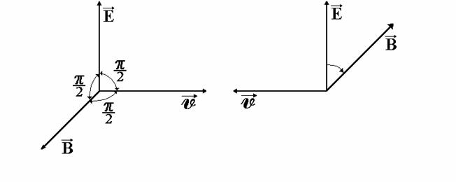
On fig. 2 shows the distribution of vectors and an electromagnetic wave along the OZ axis in this moment time t.
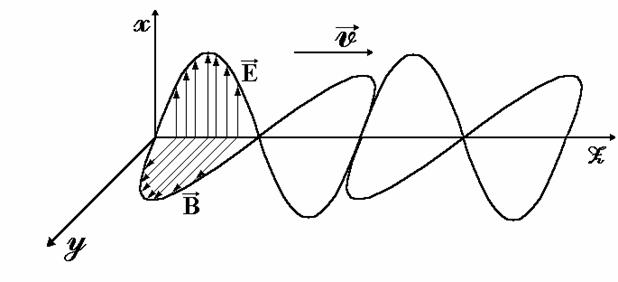 rice. 2
It follows from formula (1) that the vectors and in an electromagnetic wave oscillate in the same phase (in-phase), i.e. they simultaneously vanish and simultaneously reach their maximum values.
Based on the fact that the electromagnetic wave is transverse, it is possible to observe phenomena associated with a certain orientation of the vectors and in space. Due to these properties, it is possible to use electromagnetic waves in radio communication.
 The first to use radio waves for wireless communication was the Russian physicist A. Popov. On May 7, 1895, Popov transmitted a message to a distance of 250 m using electromagnetic waves (the words "Heinrich Hertz" were transmitted). To receive messages, Popov used the ability of metal powders to stick together under the influence of high-frequency electrical vibrations and thereby increase their electrical conductivity. A grounded antenna A served as the transmitter. In the transmitter circuit, B is a high alternating voltage source powered by battery E. When the key K is closed, a spark is formed in the spark gap, which is an oscillatory process, as a result of which the antenna Transmitter and receiver ..
It starts emitting radio waves. These waves, reaching the antenna A ' of the receiving station, excite electromagnetic oscillations in the circuit containing the grounded antenna and the coherer T. The resistance of the coherer decreases sharply, as a result of which the battery circuit E ' is closed, in which there is an electromagnetic relay that attracts the hammer F. At the same time, at point O closes the circuit of a more powerful battery E ", acting on the writing apparatus LM. At the same time, the hammer D strikes the coherer T and opens the circuit of the battery E' (to receive the next signal).
This radio became the progenitor not only for modern radio, but also for televisions, radio telescopes, mobile phones and for many other things without which people cannot imagine their life today.
Modern radio receivers are completely different from their progenitor, but the principle of operation remains the same as in Popov's receivers. A modern receiver also has an antenna in which the incoming wave causes very weak magnetic oscillations. As in the Popov receiver, the energy of these oscillations is not used directly for reception. Weak signals only control the energy sources that feed the subsequent circuits. Now such control is carried out using semiconductor devices.
In 1899, the possibility of receiving signals using a telephone was discovered. At the beginning of 1900, radio communication was successfully used during rescue operations in the Gulf of Finland. With the participation of Popov, the introduction of radio communications in the navy and army of Russia began.
Abroad, the improvement of such devices was carried out by a company organized by the Italian scientist Marconi. Experiments carried out on a large scale made it possible to carry out radiotelegraphic transmission across the Atlantic Ocean.
The most important stage in the development of radio communications was the creation in 1913 of a generator of undamped electromagnetic oscillations.
In addition to the transmission of telegraph signals, consisting of short and longer pulses of electromagnetic waves, reliable and high-quality radiotelephone communications became possible - the transmission of speech and music using electromagnetic waves.
In radiotelephone communication, air pressure fluctuations in a sound wave are converted by a microphone into electrical vibrations of the same form. It would seem that if these oscillations are amplified and fed into the antenna, then it will be possible to transmit speech and music over distances using electromagnetic waves. However, in reality, such a method of transmission is not feasible.
The fact is that sound frequency oscillations are relatively slow oscillations, and electromagnetic waves of low
(audio) frequencies are almost not emitted at all.
To transmit these waves over long distances, they must be converted into oscillations. high frequency, but so as not to spoil the information they carry. The process of converting low frequency electromagnetic oscillations into high frequency oscillations is called modulation. Amplitude modulation is used to convert sound waves.
 In the process of modulation, the amplitude of low-frequency signals is superimposed on a high-frequency signal.
Modulation is a slow process. These are such changes in a high-frequency oscillatory system, in which it manages to make a lot of high-frequency oscillations before their amplitude changes noticeably.
Without modulation, there is no telegraph, telephone, or television transmission.
 To implement amplitude modulation of electromagnetic oscillations of high frequency, a transformer coil is connected in series with the oscillatory circuit in the electrical circuit of the transistor generator. An alternating audio frequency voltage is supplied to the second coil of the transformer, for example, from the microphone output after the necessary amplification. An alternating current in the second coil of the transformer causes a voltage to appear at the ends of the first coil of the transformer.
The alternating voltage of the audio frequency is added to the constant voltage of the current source; voltage changes between the emitter and collector of the transistor lead to changes with an audio frequency in the amplitude of oscillations of the high frequency current in the generator circuit. Such high frequency oscillations are called amplitude modulated.
The radio transmitter antenna is inductively connected to the oscillatory circuit of the generator. The forced oscillations of the high frequency current occurring in the antenna create electromagnetic waves.
 Electromagnetic waves emitted by the antenna of a radio transmitter cause forced oscillations of free electrons in any conductor. The voltage between the ends of the conductor, in which the electromagnetic wave excites forced oscillations of the electric current, is proportional to the length of the conductor. Therefore, to receive electromagnetic waves in the simplest detector radio receiver, a long wire is used - a receiving antenna (1). In order to listen to only one radio transmission, the voltage fluctuations are not directed directly to the input of the amplifier, but are first fed to an oscillatory circuit (2) with a changing natural oscillation frequency. A change in the natural frequency of oscillations in the receiver circuit is usually carried out by changing the electric capacitance of a variable capacitor. When the frequency of forced oscillations in the antenna coincides with the natural frequency of the circuit, resonance sets in, while the amplitude of the forced oscillations of the voltage on the circuit capacitor plates reaches its maximum value. Thus, from a large number of electromagnetic oscillations excited in the antenna, oscillations of the desired frequency are distinguished.
From the oscillatory circuit of the receiver, modulated high-frequency oscillations arrive at the detector (3). As a detector, you can use a semiconductor diode that passes high-frequency alternating current in only one direction. During each half-cycle of high frequency, current pulses charge the capacitor (4), at the same time the capacitor is slowly discharged through the resistor (5). If the values of the capacitance of the capacitor and the electrical resistance of the resistor are chosen correctly, then a current will flow through the resistor, changing in time with the sound frequency used when modulating the oscillations in the radio transmitter. To convert electrical vibrations into sound, an alternating voltage of sound frequency is applied to the telephone (6).
The detector radio is very imperfect. It has very low sensitivity and therefore can only successfully receive radio transmissions from powerful radio stations or from nearby radio transmitters.
To increase the sensitivity in modern radio receivers, the signal from the oscillatory circuit is fed to the input of a high-frequency amplifier (UHF), and from the output of the amplifier, high-frequency electrical oscillations are fed to the detector. To increase power sound signal At the output of the radio receiver, electrical oscillations of sound frequency from the output of the detector are fed to the input of a low-frequency amplifier.
The alternating voltage of the audio frequency from the ULF output is fed to the speaker.
To amplify electrical oscillations of high and low frequencies, circuits with electronic tubes or transistors can be used.
Thanks to radio waves, our universe is known, and the elementary particles of matter are discovered. Even living things emit radio waves, and animals such as hammerhead fish use them to hunt.
Topics of the USE codifier: free electromagnetic oscillations, oscillatory circuit, forced electromagnetic oscillations, resonance, harmonic electromagnetic oscillations.
Electromagnetic vibrations are periodic changes in charge, current and voltage that occur in electrical circuit. The simplest system an oscillatory circuit is used to observe electromagnetic oscillations.
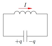
Oscillatory circuit
Oscillatory circuit It is a closed circuit formed by a capacitor and a coil connected in series.
We charge the capacitor, connect a coil to it and close the circuit. will start happening free electromagnetic oscillations- periodic changes in the charge on the capacitor and the current in the coil. We recall that these oscillations are called free because they occur without any external influence - only due to the energy stored in the circuit.
We denote the period of oscillations in the circuit, as always, through . The resistance of the coil will be considered equal to zero.
Let's consider everything in detail important stages oscillation process. For greater clarity, we will draw an analogy with the oscillations of a horizontal spring pendulum.
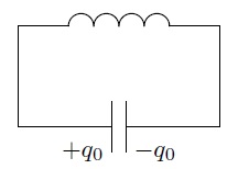
Starting moment: . The charge of the capacitor is equal, there is no current through the coil (Fig. 1). The capacitor will now start to discharge.

Rice. 1.
Despite the fact that the resistance of the coil is zero, the current will not increase instantly. As soon as the current begins to increase, an EMF of self-induction will appear in the coil, which prevents the current from increasing.
Analogy. The pendulum is pulled to the right by a value and is released at the initial moment. The initial speed of the pendulum is zero.
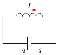
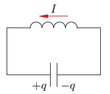
First quarter of the period: . The capacitor is discharging, its current charge is . The current through the coil increases (Fig. 2).
Rice. 2.
The increase in current occurs gradually: the eddy electric field of the coil prevents the increase in current and is directed against the current.
Analogy. The pendulum moves to the left towards the equilibrium position; the speed of the pendulum gradually increases. The deformation of the spring (it is also the coordinate of the pendulum) decreases.
End of the first quarter: . The capacitor is completely discharged. The current strength has reached its maximum value (Fig. 3). The capacitor will now start charging.

Rice. 3.
The voltage on the coil is zero, but the current will not disappear instantly. As soon as the current begins to decrease, an EMF of self-induction will appear in the coil, preventing the current from decreasing.
Analogy. The pendulum passes the equilibrium position. Its speed reaches its maximum value. The spring deflection is zero.
Second quarter: . The capacitor is recharged - a charge of the opposite sign appears on its plates compared to what it was at the beginning ( fig. 4).
Rice. 4.
The current strength decreases gradually: the eddy electric field of the coil, supporting the decreasing current, is co-directed with the current.
Analogy. The pendulum continues to move to the left - from the equilibrium position to the right extreme point. Its speed gradually decreases, the deformation of the spring increases.
End of second quarter. The capacitor is completely recharged, its charge is again equal (but the polarity is different). The current strength is zero (Fig. 5). Now the reverse charge of the capacitor will begin.
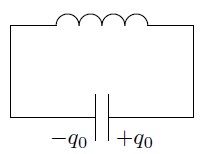
Rice. 5.
Analogy. The pendulum has reached its extreme right point. The speed of the pendulum is zero. The deformation of the spring is maximum and equal to .
third quarter: . The second half of the oscillation period began; processes went in the opposite direction. The capacitor is discharged ( fig. 6).
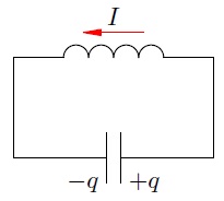
Rice. 6.
Analogy. The pendulum moves back: from the right extreme point to the equilibrium position.
End of the third quarter: . The capacitor is completely discharged. The current is maximum and is again equal, but this time it has a different direction (Fig. 7).
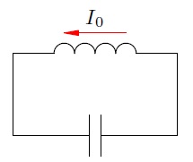
Rice. 7.
Analogy. The pendulum again passes the equilibrium position with maximum speed but this time in the opposite direction.
fourth quarter: . The current decreases, the capacitor is charged ( fig. 8).
Rice. 8.
Analogy. The pendulum continues to move to the right - from the equilibrium position to the leftmost point.
End of the fourth quarter and the entire period: . The reverse charge of the capacitor is completed, the current is zero (Fig. 9).
Rice. 9.
This moment is identical to the moment , and this picture is the picture 1 . There was one complete wobble. Now the next oscillation will begin, during which the processes will occur in exactly the same way as described above.
Analogy. The pendulum returned to its original position.
The considered electromagnetic oscillations are undamped- they will continue indefinitely. After all, we assumed that the resistance of the coil is zero!
In the same way, the oscillations of a spring pendulum will be undamped in the absence of friction.
In reality, the coil has some resistance. Therefore, oscillations in a real oscillatory circuit will be damped. So, after one complete oscillation, the charge on the capacitor will be less than the initial value. Over time, the oscillations will completely disappear: all the energy initially stored in the circuit will be released in the form of heat at the resistance of the coil and connecting wires.
In the same way, the vibrations of a real spring pendulum will be damped: all the energy of the pendulum will gradually turn into heat due to the inevitable presence of friction.
Energy transformations in an oscillatory circuit
We continue to consider undamped oscillations in the circuit, assuming the resistance of the coil to be zero. The capacitor has a capacitance, the inductance of the coil is equal to.
Since there is no heat loss, the energy does not leave the circuit: it is constantly redistributed between the capacitor and the coil.
Let's take the moment of time when the charge of the capacitor is maximum and equal to , and there is no current. The energy of the magnetic field of the coil at this moment is zero. All the energy of the circuit is concentrated in the capacitor:
Now, on the contrary, consider the moment when the current is maximum and equal to, and the capacitor is discharged. The energy of the capacitor is zero. All the energy of the circuit is stored in the coil:
At an arbitrary point in time, when the charge of the capacitor is equal and current flows through the coil, the energy of the circuit is equal to:
Thus,
(1)
Relation (1) is used in solving many problems.
Electromechanical analogies
In the previous leaflet about self-induction, we noted the analogy between inductance and mass. Now we can establish a few more correspondences between electrodynamic and mechanical quantities.
For a spring pendulum we have a relation similar to (1) :
(2)
Here, as you already understood, is the stiffness of the spring, is the mass of the pendulum, and are the current values of the coordinate and velocity of the pendulum, and are their maximum values.
Comparing equalities (1) and (2) with each other, we see the following correspondences:
(3)
(4)
(5)
(6)
Based on these electromechanical analogies, we can foresee a formula for the period of electromagnetic oscillations in an oscillatory circuit.
Indeed, the period of oscillation of a spring pendulum, as we know, is equal to:
In accordance with analogies (5) and (6), we replace here the mass with inductance, and the stiffness with reverse capacitance. We get:
(7)
Electromechanical analogies do not fail: formula (7) gives the correct expression for the oscillation period in the oscillatory circuit. It is called Thomson's formula. We will present its more rigorous derivation shortly.
Harmonic law of oscillations in the circuit
Recall that oscillations are called harmonic, if the fluctuating value changes with time according to the law of sine or cosine. If you managed to forget these things, be sure to repeat the sheet “Mechanical vibrations”.
The oscillations of the charge on the capacitor and the current strength in the circuit turn out to be harmonic. We will prove it now. But first we need to establish the rules for choosing the sign for the charge of the capacitor and for the strength of the current - after all, during fluctuations, these quantities will take on both positive and negative values.
First we choose positive bypass direction contour. The choice does not play a role; let that be the direction counterclock-wise(Fig. 10).
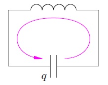
Rice. 10. Positive bypass direction
The current strength is considered positive style="vertical-align:-20%;" class="tex" alt=""> if the current flows in the positive direction. Otherwise, the current will be negative.
The charge of a capacitor is the charge of that plate to which a positive current flows (i.e., the plate indicated by the bypass direction arrow). IN this case- charge left capacitor plates.
With such a choice of signs of current and charge, the relation is true: (with a different choice of signs, it could happen). Indeed, the signs of both parts are the same: if style="vertical-align:-20%;" class="tex" alt="">, then the charge of the left plate increases, and therefore style="vertical-align:-20%;" class="tex" alt="">.
The values and change with time, but the energy of the circuit remains unchanged:
(8)
Therefore, the time derivative of energy vanishes: . We take the time derivative of both parts of the relation (8) ; do not forget that complex functions are differentiated on the left (If is a function of , then according to the rule of differentiation of a complex function, the derivative of the square of our function will be equal to: ):
Substituting here and , we get:
But the strength of the current is not a function identically equal to zero; That's why
Let's rewrite this as:
(9)
We have obtained a differential equation of harmonic oscillations of the form , where . This proves that the charge of a capacitor oscillates according to a harmonic law (i.e., according to the law of sine or cosine). The cyclic frequency of these oscillations is equal to:
(10)
This value is also called natural frequency contour; it is with this frequency that free (or, as they say, own fluctuations). The oscillation period is:
We again came to the Thomson formula.
Harmonic dependence of charge on time in general case looks like:
(11)
The cyclic frequency is found by the formula (10) ; the amplitude and initial phase are determined from the initial conditions.
We will consider the situation discussed in detail at the beginning of this leaflet. Let the charge of the capacitor be maximum and equal to (as in Fig. 1); there is no current in the loop. Then the initial phase is , so that the charge varies according to the cosine law with amplitude :
(12)
Let's find the law of change of current strength. To do this, we differentiate relation (12) with respect to time, again not forgetting the rule for finding the derivative of a complex function:
We see that the current strength also changes according to the harmonic law, this time according to the sine law:
(13)
The amplitude of the current strength is:
The presence of a "minus" in the law of current change (13) is not difficult to understand. Let's take, for example, the time interval (Fig. 2).
Current flows in the negative direction: . Since , the oscillation phase is in the first quarter: . The sine in the first quarter is positive; therefore, the sine in (13) will be positive in the considered time interval. Therefore, to ensure the negativity of the current, the minus sign in formula (13) is really necessary.
Now look at fig. 8 . The current flows in the positive direction. How does our "minus" work in this case? Find out what's going on here!
Let's depict the graphs of charge and current fluctuations, i.e. graphs of functions (12) and (13) . For clarity, we present these graphs in the same coordinate axes (Fig. 11).
![]()
Rice. 11. Graphs of fluctuations in charge and current
Note that charge zeros occur at current highs or lows; conversely, current zeros correspond to charge maxima or minima.
Using the cast formula
we write the law of current change (13) in the form:
Comparing this expression with the law of charge change, we see that the phase of the current, equal to , is greater than the phase of the charge by . In this case, the current is said to leading in phase charge on ; or phase shift between current and charge is equal to; or phase difference between current and charge is equal to .
Leading the charge current in phase on graphically manifests itself in the fact that the current graph is shifted to the left on relative to the charge graph. The current strength reaches, for example, its maximum a quarter of the period earlier than the charge reaches its maximum (and a quarter of the period just corresponds to the phase difference).


