ABSTRACT
ON THIS TOPIC:
Jet Engines .
WRITTEN: Kiselev A.V.
KALININGRAD
Introduction
Jet engine, an engine that creates the traction force necessary for movement by converting the initial energy into the kinetic energy of the jet stream of the working fluid; as a result of the expiration of the working fluid from the nozzle of the engine, a reactive force is formed in the form of a reaction (recoil) of the jet, which moves the engine and the apparatus structurally associated with it in the direction opposite to the outflow of the jet. The kinetic (speed) energy of a jet stream can be converted into R. j. different kinds energy (chemical, nuclear, electrical, solar). A direct reaction engine (direct reaction engine) combines the engine itself with a mover, that is, it provides its own movement without the participation of intermediate mechanisms.
For creating jet thrust used by R. d., you need:
the source of the initial (primary) energy, which is converted into the kinetic energy of the jet;
working body, which in the form of a jet stream is ejected from the R. d .;
R. D. himself is an energy converter.
The initial energy is stored on board an aircraft or other apparatus equipped with R.D. (chemical fuel, nuclear fuel), or (in principle) can come from outside (the energy of the Sun). To obtain a working fluid in R. d., a substance selected from environment(for example, air or water);
the substance which is in tanks of the device or directly in the R.'s chamber of d.; a mixture of substances coming from the environment and stored on board the vehicle.
In modern R. d., chemical is most often used as the primary
Missile firing tests
engine Space Shuttle
Turbojet engines AL-31F aircraft Su-30MK. belong to the class jet engines
energy. In this case, the working fluid is incandescent gases - combustion products of chemical fuel. During the operation of R. D., the chemical energy of burning substances is converted into thermal energy of combustion products, and the thermal energy of hot gases is converted into mechanical energy forward movement jet stream and, consequently, the apparatus on which the engine is installed. The main part of any R. d. is the combustion chamber in which the working fluid is generated. The end part of the chamber, which serves to accelerate the working fluid and obtain a jet stream, is called a jet nozzle.
Depending on whether the environment is used or not during the operation of rocket engines, they are divided into 2 main classes - air-jet engines (WRD) and rocket engines (RD). All WFDs are heat engines, the working fluid of which is formed by the oxidation reaction of a combustible substance with atmospheric oxygen. The air coming from the atmosphere makes up the bulk of the working fluid of the WFD. Thus, an apparatus with a WFD carries a source of energy (fuel) on board, and draws most of the working fluid from the environment. Unlike the WFD, all components of the working fluid of the RD are on board the apparatus equipped with the RD. The absence of a propulsor interacting with the environment and the presence of all components of the working fluid on board the apparatus make the RD the only one suitable for work in space. There are also combined rocket engines, which are, as it were, a combination of both main types.
History of jet engines
The principle of jet propulsion has been known for a very long time. Heron's ball can be considered the ancestor of R. d. Solid rocket engines - powder rockets appeared in China in the 10th century. n. e. For hundreds of years, such missiles were used first in the East, and then in Europe as fireworks, signal, combat. In 1903, K. E. Tsiolkovsky, in his work "Investigation of World Spaces with Reactive Instruments", was the first in the world to put forward the main provisions of the theory of liquid-propellant rocket engines and proposed the main elements of a liquid-propellant rocket engine. The first Soviet liquid rocket engines - ORM, ORM-1, ORM-2 were designed by V. P. Glushko and created under his leadership in 1930-31 at the Gas Dynamics Laboratory (GDL). In 1926, R. Goddard launched a rocket using liquid fuel. For the first time, an electrothermal RD was created and tested by Glushko at the GDL in 1929-33.
In 1939, missiles with ramjet engines designed by I. A. Merkulov were tested in the USSR. First scheme turbojet engine? was proposed by the Russian engineer N. Gerasimov in 1909.
In 1939, the construction of turbojet engines designed by A. M. Lyulka began at the Kirov Plant in Leningrad. The tests of the created engine were prevented by the Great Patriotic War of 1941-45. In 1941, a turbojet engine designed by F. Whittle (Great Britain) was first installed on an aircraft and tested. The theoretical works of the Russian scientists S. S. Nezhdanovsky, I. V. Meshchersky, and N. E. Zhukovsky, the works of the French scientist R. Enot-Peltri, and the German scientist G. Oberth were of great importance for the creation of R. D.. An important contribution to the creation of the VRD was the work of the Soviet scientist B. S. Stechkin "Theory of an air-breathing engine", published in 1929.
R. d. have a different purpose and the scope of their application is constantly expanding.


R. d. are most widely used on various types of aircraft.


Turbojet engines and dual-circuit turbojet engines are equipped with most military and civil aircraft around the world, they are used in helicopters. These rocket engines are suitable for flights at both subsonic and supersonic speeds; they are also installed on projectile aircraft; supersonic turbojet engines can be used in the first stages of aerospace aircraft. Ramjet engines are installed on anti-aircraft guided missiles, cruise missiles, supersonic fighter-interceptors. Subsonic ramjet engines are used in helicopters (installed at the ends of the main rotor blades). Pulsating jet engines have little thrust and are intended only for aircraft at subsonic speeds. During the 2nd World War of 1939-45, these engines were equipped with V-1 projectiles.
RD in most cases are used on high-speed aircraft.
Liquid-propellant rocket engines are used on launch vehicles of spacecraft and spacecraft as marching, braking and control engines, as well as on guided ballistic missiles. Solid-propellant rocket engines are used in ballistic, anti-aircraft, anti-tank, and other military missiles, as well as on launch vehicles and spacecraft. Small solid propellant engines are used as boosters for aircraft takeoff. Electric rocket engines and nuclear rocket engines can be used in spacecraft.

However, this mighty trunk, the principle of direct reaction, gave life to a huge crown of the "family tree" of the family of jet engines. To get acquainted with the main branches of its crown, crowning the "trunk" of the direct reaction. Soon, as can be seen from the figure (see below), this trunk is divided into two parts, as if split by a lightning strike. Both new trunks are equally decorated with mighty crowns. This division occurred due to the fact that all "chemical" jet engines are divided into two classes, depending on whether they use ambient air for their work or not.

One of the newly formed trunks is the class of air-breathing engines (VRD). As the name suggests, they cannot operate outside of the atmosphere. That's why these engines are the basis modern aviation both manned and unmanned. WFDs use atmospheric oxygen to burn fuel; without it, the combustion reaction in the engine will not proceed. But still, turbojet engines are currently the most widely used.
(TRD), installed on almost all modern aircraft without exception. Like all engines using atmospheric air, turbojet engines need a special device to compress the air before it enters the combustion chamber. After all, if the pressure in the combustion chamber does not significantly exceed atmospheric pressure, then the gases will not flow out of the engine at a higher speed - it is the pressure that pushes them out. But at a low exhaust velocity, the thrust of the engine will be small, and the engine will consume a lot of fuel, such an engine will not find application. In a turbojet engine, a compressor is used to compress the air, and the design of the engine largely depends on the type of compressor. There are engines with axial and centrifugal compressors, axial compressors can have fewer or more compression stages thanks to using our system, be one-two-stage, etc. To drive the compressor, the turbojet engine has a gas turbine, which gave the name to the engine. Due to the compressor and turbine, the design of the engine is very complex.
Air-jet engines without compressors are much simpler in design, in which the necessary pressure increase is carried out in other ways, which have names: pulsating and ramjet engines.
In a pulsating engine, this is usually done by a valve grill installed at the engine inlet, when a new portion of the fuel-air mixture fills the combustion chamber and a flash occurs in it, the valves close, isolating the combustion chamber from the engine inlet. As a result, the pressure in the chamber rises, and the gases rush out through the jet nozzle, after which the whole process is repeated.
In a compressorless engine of another type, a ramjet, there is not even this valve grid and the pressure in the combustion chamber rises as a result of dynamic pressure, i.e. deceleration of the oncoming air flow entering the engine in flight. It is clear that such an engine is able to work only when the aircraft is already flying at a sufficiently high speed, it will not develop thrust in the parking lot. But at a very high speed, 4-5 times the speed of sound, the ramjet develops very high thrust and consumes less fuel than any other "chemical" jet engine under these conditions. That's why ramjet motors.
The peculiarity of the aerodynamic scheme of supersonic aircraft with ramjet engines (ramjet engines) is due to the presence of special accelerating engines that provide the speed necessary to start stable operation of the ramjet. This makes the tail part of the structure heavier and requires the installation of stabilizers to ensure the necessary stability.
The principle of operation of a jet engine.
At the heart of modern powerful jet engines of various types is the principle of direct reaction, i.e. the principle of creating a driving force (or thrust) in the form of a reaction (recoil) of a jet of "working substance" flowing out of the engine, usually hot gases.
In all engines, there are two processes of energy conversion. First, the chemical energy of the fuel is converted into thermal energy of the combustion products, and then the thermal energy is used to perform mechanical work. Such engines include reciprocating engines of automobiles, diesel locomotives, steam and gas turbines of power plants, etc.
Consider this process in relation to jet engines. Let's start with the combustion chamber of the engine, in which a combustible mixture has already been created in one way or another, depending on the type of engine and the type of fuel. This can be, for example, a mixture of air and kerosene, as in a turbojet engine of a modern jet aircraft, or a mixture of liquid oxygen and alcohol, as in some liquid rocket engines, or, finally, some kind of solid propellant for powder rockets. The combustible mixture can burn, i.e. enter into a chemical reaction with a rapid release of energy in the form of heat. The ability to release energy during a chemical reaction is the potential chemical energy of the molecules of the mixture. The chemical energy of molecules is related to the features of their structure, more precisely, the structure of their electron shells, i.e. the electron cloud that surrounds the nuclei of the atoms that make up the molecule. As a result of a chemical reaction, in which some molecules are destroyed, while others are formed, a rearrangement of the electron shells naturally occurs. In this restructuring, it is the source of released chemical energy. It can be seen that only substances that, during a chemical reaction in the engine (combustion), emit a sufficiently large amount of heat, and also form a large amount of gases, can serve as fuels for jet engines. All these processes take place in the combustion chamber, but let's dwell on the reaction not at the molecular level (this has already been discussed above), but at the "phases" of work. Until combustion has begun, the mixture has a large supply of potential chemical energy. But then the flame engulfed the mixture, another moment - and the chemical reaction is over. Now instead of molecules combustible mixture the chamber is filled with more densely "packed" molecules of combustion products. The excess binding energy, which is the chemical energy of the combustion reaction that has taken place, has been released. Molecules possessing this excess energy almost instantly transferred it to other molecules and atoms as a result of frequent collisions with them. All molecules and atoms in the combustion chamber began to randomly, chaotically move at a much higher speed, the temperature of the gases increased. So there was a transition of the potential chemical energy of the fuel into the thermal energy of the combustion products.
A similar transition was carried out in all other heat engines, but jet engines fundamentally differ from them in relation to the further fate of hot combustion products.
After hot gases have formed in the heat engine, containing large thermal energy, this energy must be converted into mechanical energy. After all, engines serve to make mechanical work, to “move” something, to put it into action, it doesn’t matter whether it is a dynamo, please add drawings of a power plant, a diesel locomotive, a car or an airplane.
In order for the thermal energy of gases to be converted into mechanical energy, their volume must increase. With such an expansion, the gases do the work for which their internal and thermal energy is expended.
When piston engine expanding gases press on the piston moving inside the cylinder, the piston pushes the connecting rod, and it already rotates the crankshaft of the engine. The shaft is connected to the rotor of a dynamo, the driving axles of a diesel locomotive or car, or the propeller of an aircraft - the engine performs useful work. IN steam engine, or a gas turbine, gases, expanding, force the wheel connected to the turbine shaft to rotate - there is no need for a transmission crank mechanism, which is one of the great advantages of the turbine
Gases expand, of course, in a jet engine, because without it they do not do work. But the expansion work in that case is not spent on the rotation of the shaft. Associated with the drive mechanism, as in other heat engines. The purpose of a jet engine is different - to create jet thrust, and for this it is necessary that a jet of gases - combustion products flow out of the engine at a high speed: the reaction force of this jet is the thrust of the engine. Consequently, the work of expanding the gaseous products of fuel combustion in the engine must be spent on accelerating the gases themselves. This means that the thermal energy of gases in a jet engine must be converted into their kinetic energy - the random chaotic thermal motion of molecules must be replaced by their organized flow in one direction common to all.
For this purpose, one of the most important parts of the engine, the so-called jet nozzle, serves. No matter what type a particular jet engine belongs to, it is necessarily equipped with a nozzle through which hot gases flow out of the engine at great speed - the products of fuel combustion in the engine. In some engines, gases enter the nozzle immediately after the combustion chamber, for example, in rocket or ramjet engines. In others, turbojets, the gases first pass through a turbine, to which they give up part of their thermal energy. It consumes in this case to drive the compressor, which serves to compress the air in front of the combustion chamber. But anyway, the nozzle is the last part of the engine - gases flow through it before leaving the engine.
The jet nozzle may have various forms, and, moreover, a different design depending on the type of engine. The main thing is the speed with which the gases flow out of the engine. If this outflow velocity does not exceed the speed with which sound waves propagate in the outflowing gases, then the nozzle is a simple cylindrical or narrowing pipe section. If the outflow velocity must exceed the speed of sound, then the nozzle is given the shape of an expanding pipe or, first, narrowing, and then expanding (Love's nozzle). Only in a tube of such a shape, as theory and experience show, is it possible to disperse the gas to supersonic speeds, to step over the "sonic barrier".
Jet engine diagram
The turbofan engine is the most widely used jet engine in civil aviation.

The fuel entering the engine (1) is mixed with compressed air and burned in the combustion chamber (2). The expanding gases rotate high-speed (3) and low-speed) turbines, which, in turn, drive the compressor (5), pushing air into the combustion chamber, and fans (6), driving air through this chamber and directing it to the exhaust pipe. By displacing air, fans provide additional thrust. An engine of this type is capable of developing thrust up to 13,600 kg.

Conclusion
The jet engine has many remarkable features, but the main one is as follows. A rocket does not need land, water, or air to move, as it moves as a result of interaction with gases formed during the combustion of fuel. Therefore, the rocket can move in airless space.
K. E. Tsiolkovsky is the founder of the theory of space flights. Scientific proof of the possibility of using a rocket for flights into outer space, beyond the earth's atmosphere and to other planets of the solar system was given for the first time by the Russian scientist and inventor Konstantin Eduardovich Tsiolkovsky
Bibliography
Encyclopedic Dictionary of the Young Technician.
Thermal Phenomena in Technology.
Materials from the site http://goldref.ru/;
jet movement (2)
Abstract >> PhysicsWhich is in the form reactive jet is ejected from reactive engine; myself reactive engine- an energy converter ... with which reactive engine affects a device equipped with this reactive engine. thrust reactive engine depends on...
jet movement in nature and technology
Abstract >> PhysicsSalp forward. Of greatest interest is reactive engine squid. The squid is the most...i.e. apparatus with reactive engine using fuel and oxidizer located on the apparatus itself. Reactive engine- This engine transforming...
Reactive multiple launch rocket system BM-13 Katyusha
Abstract >> Historical figureshead and gunpowder reactive engine. The head part in its own way ... a fuse and an additional detonator. Reactive engine has a combustion chamber, in ... a sharp increase in fire capabilities reactive
JET ENGINE, an engine that creates the traction force necessary for movement by converting potential energy into kinetic energy of the jet stream of the working fluid. Under the working fluid m, in relation to engines, is understood a substance (gas, liquid, solid), with the help of which the thermal energy released during the combustion of fuel is converted into useful mechanical work. As a result of the expiration of the working fluid from the engine nozzle, a reactive force is formed in the form of a reaction (recoil) of a jet directed in space in the direction opposite to the outflow of the jet. Various types of energy (chemical, nuclear, electrical, solar) can be converted into the kinetic (speed) energy of a jet stream in a jet engine.
A jet engine (direct reaction engine) combines the engine itself with a propeller, that is, it provides its own movement without the participation of intermediate mechanisms. To create jet thrust (engine thrust) used by a jet engine, you need: a source of initial (primary) energy, which is converted into the kinetic energy of the jet stream; the working fluid, which is ejected from the jet engine in the form of a jet stream; the jet engine itself is an energy converter. Engine thrust - this is a reactive force, which is the result of gas-dynamic forces of pressure and friction applied to the internal and external surfaces of the engine. Distinguish between internal thrust (reactive thrust) - the resultant of all gas-dynamic forces applied to the engine, without taking into account external resistance and effective thrust, taking into account the external resistance of the power plant. The initial energy is stored on board an aircraft or other apparatus equipped with a jet engine (chemical fuel, nuclear fuel), or (in principle) can come from outside (solar energy).
To obtain a working fluid in a jet engine, a substance taken from the environment (for example, air or water) can be used; a substance located in the tanks of the apparatus or directly in the chamber of a jet engine; a mixture of substances coming from the environment and stored on board the apparatus. Modern jet engines most often use chemical energy as primary energy. In this case, the working fluid is incandescent gases - combustion products of chemical fuel. During the operation of a jet engine, the chemical energy of the burning substances is converted into the thermal energy of the combustion products, and the thermal energy of the hot gases is converted into the mechanical energy of the forward motion of the jet and, consequently, the apparatus on which the engine is installed.
The principle of operation of a jet engine
In a jet engine (Fig. 1), a jet of air enters the engine, meets with turbines rotating at great speed compressor , which draws air from external environment(using built-in fan). Thus, two tasks are solved - the primary air intake and the cooling of the entire engine as a whole. Compressor turbine blades compress the air by about 30 times or more and "push" it (inject) into the combustion chamber (the working fluid is generated), which is the main part of any jet engine. The combustion chamber also acts as a carburetor, mixing fuel with air. This can be, for example, a mixture of air and kerosene, as in a turbojet engine of a modern jet aircraft, or a mixture of liquid oxygen and alcohol, as in some liquid rocket engines, or some kind of solid propellant for powder rockets. After education fuel-air mixture it is ignited and energy is released in the form of heat, i.e., jet engines can only be fueled by substances that, during a chemical reaction in the engine (combustion), release a lot of heat, and also form a large amount of gases.
In the process of ignition, there is a significant heating of the mixture and surrounding parts, as well as volumetric expansion. In fact, the jet engine uses a controlled explosion for propulsion. The combustion chamber of a jet engine is one of its hottest parts (the temperature in it reaches 2700 ° C), it must be constantly cooled intensively. The jet engine is equipped with a nozzle through which hot gases, the products of fuel combustion in the engine, flow out of the engine at great speed. In some engines, gases enter the nozzle immediately after the combustion chamber, for example, in rocket or ramjet engines. In turbojet engines, the gases after the combustion chamber first pass through turbine , which is given part of its thermal energy to drive a compressor that compresses air in front of the combustion chamber. But anyway, the nozzle is the last part of the engine - gases flow through it before leaving the engine. It forms a direct jet stream. The nozzle is sent cold air, pumped by the compressor to cool the internal parts of the engine. The jet nozzle may have various shapes and designs depending on the type of engine. If the outflow velocity must exceed the speed of sound, then the nozzle is given the shape of an expanding pipe, or first narrowing and then expanding (Laval nozzle). Only in a pipe of this shape can gas be accelerated to supersonic speeds, to step over the "sonic barrier".
Depending on whether or not the environment is used during the operation of a jet engine, they are divided into two main classes - jet engines(WFD) and rocket engines(RD). All WFD - heat engines, the working fluid of which is formed during the oxidation reaction of a combustible substance with atmospheric oxygen. The air coming from the atmosphere makes up the bulk of the working fluid of the WFD. Thus, an apparatus with a WFD carries a source of energy (fuel) on board, and draws most of the working fluid from the environment. These include turbojet engine (TRD), ramjet engine (ramjet), pulsed jet engine (PuVRD), hypersonic ramjet engine (scramjet). Unlike the WFD, all components of the working fluid of the RD are on board the vehicle equipped with the RD. The absence of a propeller interacting with the environment and the presence of all components of the working fluid on board the vehicle make the RD suitable for space operation. There are also combined rocket engines, which are, as it were, a combination of both main types.
Main characteristics of jet engines
Main technical parameter characterizing a jet engine is thrust - the force that develops the engine in the direction of movement of the device, specific impulse - the ratio of engine thrust to the mass of rocket fuel (working fluid) consumed in 1 s, or an identical characteristic - specific consumption fuel (the amount of fuel consumed in 1 s per 1 N of thrust developed by a jet engine), engine specific gravity (mass of a jet engine in working condition per unit of thrust developed by it). For many types of jet engines important characteristics are dimensions and resource. Specific impulse is an indicator of the degree of perfection or quality of the engine. The above diagram (Fig. 2) graphically presents the upper values of this indicator for different types jet engines depending on the flight speed, expressed in the form of a Mach number, which allows you to see the scope of each type of engine. This indicator is also a measure of the efficiency of the engine.
Thrust - the force with which a jet engine acts on a device equipped with this engine - is determined by the formula: $$P = mW_c + F_c (p_c - p_n),$$ where $m$ is mass flow(mass consumption) of the working fluid for 1 s; $W_c$ is the speed of the working fluid in the nozzle section; $F_c$ is the area of the outlet section of the nozzle; $p_c$ – gas pressure in the nozzle section; $p_n$ – ambient pressure (usually atmospheric pressure). As can be seen from the formula, the thrust of a jet engine depends on the ambient pressure. It is greatest in emptiness and least of all in the densest layers of the atmosphere, i.e., it varies depending on the flight altitude of an apparatus equipped with a jet engine above sea level, if flight in the Earth’s atmosphere is considered. The specific impulse of a jet engine is directly proportional to the speed of the outflow of the working fluid from the nozzle. The outflow rate increases with an increase in the temperature of the outgoing working fluid and a decrease in the molecular weight of the fuel (the lower the molecular weight of the fuel, the greater the volume of gases formed during its combustion, and, consequently, the rate of their outflow). Since the rate of exhaust of combustion products (working fluid) is determined by the physicochemical properties of the fuel components and design features engine, being a constant value at not very big changes mode of operation of a jet engine, then the magnitude of the reactive force is determined mainly by the mass per second fuel consumption and varies over a very wide range (a minimum for electric ones - a maximum for liquid and solid rocket engines). Low-thrust jet engines are mainly used in aircraft stabilization and control systems. In space, where gravitational forces are felt weakly and there is practically no medium, the resistance of which would have to be overcome, they can also be used for overclocking. RD with maximum thrust is necessary for launching rockets at long ranges and altitudes, and especially for launching aircraft into space, i.e., for accelerating them to first space velocity. Such engines consume a very large amount of fuel; they usually work for a very short time, accelerating the rockets to a given speed.
WFDs use ambient air as the main component of the working fluid, which is much more economical. WJDs can operate continuously for many hours, making them suitable for aviation use. Miscellaneous schemes allowed them to be used for aircraft operated on different modes flight. Turbojet engines (TRDs) are widely used, which are installed on almost all modern aircraft without exception. Like all engines that use atmospheric air, turbojet engines need a special device to compress the air before it enters the combustion chamber. In a turbojet engine, a compressor is used to compress the air, and the design of the engine largely depends on the type of compressor. Uncompressor jet engines are much simpler in design, in which the necessary pressure increase is carried out in other ways; these are pulsating and direct-flow motors. In a pulsating jet engine (PUVRD), this is usually done by a valve grill installed at the engine inlet, when a new portion of the fuel-air mixture fills the combustion chamber and a flash occurs in it, the valves close, isolating the combustion chamber from the engine inlet. As a result, the pressure in the chamber rises, and the gases rush out through the jet nozzle, after which the whole process is repeated. In a non-compressor engine of another type, a ramjet, there is not even this valve array and atmospheric air, entering the engine inlet at a speed equal to the flight speed, is compressed due to the velocity pressure and enters the combustion chamber. The injected fuel burns, the heat content of the flow increases, which flows out through the jet nozzle at a speed greater than the flight speed. Due to this, the jet thrust of the ramjet is created. The main disadvantage of the ramjet is the inability to independently provide takeoff and acceleration of the aircraft (LA). It is required first to accelerate the aircraft to a speed at which the ramjet is launched and its stable operation is ensured. The peculiarity of the aerodynamic scheme of supersonic aircraft with ramjet engines (ramjet engines) is due to the presence of special accelerating engines that provide the speed necessary to start stable operation of the ramjet. This makes the tail part of the structure heavier and requires the installation of stabilizers to ensure the necessary stability.
Historical reference
The principle of jet propulsion has been known for a long time. Heron's ball can be considered the ancestor of the jet engine. Solid rocket motors(RDTT - solid fuel rocket engine) - powder rockets appeared in China in the 10th century. n. e. For hundreds of years, such missiles were used first in the East, and then in Europe as fireworks, signal, combat. An important milestone in the development of the idea of jet propulsion was the idea of using a rocket as an engine for an aircraft. It was first formulated by the Russian revolutionary Narodnaya Volya N. I. Kibalchich, who in March 1881, shortly before his execution, proposed a scheme for an aircraft (rocket plane) using jet propulsion from explosive powder gases. Solid propellant rocket engines are used in all classes of military missiles (ballistic, anti-aircraft, anti-tank, etc.), in space (for example, as starting and sustainer engines) and aviation technology (aircraft take-off boosters, in systems ejection), etc. Small solid propellant engines are used as boosters for aircraft takeoff. Electric rocket engines and nuclear rocket engines can be used in spacecraft.
Turbojet engines and dual-circuit turbojet engines are equipped with most military and civil aircraft around the world, they are used in helicopters. These jet engines are suitable for flights at both subsonic and supersonic speeds; they are also installed on projectile aircraft, supersonic turbojet engines can be used in the first stages aerospace aircraft, rocket and space technology, etc.
Of great importance for the creation of jet engines were the theoretical works of Russian scientists S. S. Nezhdanovsky, I. V. Meshchersky, N. E. Zhukovsky, the works of the French scientist R. Enot-Peltri, the German scientist G. Oberth. An important contribution to the creation of the VRD was the work of the Soviet scientist B. S. Stechkin, The Theory of an Air Jet Engine, published in 1929. Practically more than 99% of aircraft use a jet engine to one degree or another.
Jet motion is a process in which one of its parts is separated from a certain body at a certain speed. The force that arises in this case works by itself, without the slightest contact with external bodies. Jet propulsion was the impetus for the creation of a jet engine. The principle of its operation is based precisely on this force. How does such an engine work? Let's try to figure it out.
Historical facts
The idea of using jet thrust, which would make it possible to overcome the force of gravity of the Earth, was put forward in 1903 by the phenomenon of Russian science - Tsiolkovsky. He published a whole study on the subject, but it was not taken seriously. Konstantin Eduardovich, having survived the change in the political system, spent years of work to prove to everyone that he was right.
Today there are a lot of rumors that the revolutionary Kibalchich was the first in this matter. But the will of this man by the time of the publication of the works of Tsiolkovsky was buried along with Kibalchich. In addition, it was not a full-fledged work, but only sketches and sketches - the revolutionary could not bring a reliable basis for theoretical calculations in his works.
How does reactive force work?
To understand how a jet engine works, you need to understand how this force works.
So, imagine a shot from any firearm. This good example reactive force. A jet of hot gas, which was formed during the combustion of the charge in the cartridge, pushes the weapon back. The more powerful the charge, the stronger the return will be.
And now imagine the process of ignition of a combustible mixture: it takes place gradually and continuously. This is exactly what the principle of operation of a ramjet engine looks like. A rocket with a solid propellant jet engine works in a similar way - this is the simplest of its variations. Even novice rocket modellers are familiar with it.
As a fuel for jet engines, black powder was first used. Jet engines, the principle of which was already more advanced, required fuel with a base of nitrocellulose, which was dissolved in nitroglycerin. In large units that launch rockets that put shuttles into orbit, today they use a special mixture of polymer fuel with ammonium perchlorate as an oxidizing agent.
The principle of operation of the RD
Now it is worth understanding the principle of operation of a jet engine. To do this, you can consider the classics - liquid engines, which have not changed much since the time of Tsiolkovsky. These units use fuel and an oxidizer.

As the latter, liquid oxygen or nitric acid is used. Kerosene is used as fuel. Modern cryogenic-type liquid engines consume liquid hydrogen. When oxidized with oxygen, it increases the specific impulse (by as much as 30 percent). The idea that hydrogen could be used was also born in Tsiolkovsky's head. However, at that time, due to the extreme explosiveness, it was necessary to look for another fuel.
The principle of operation is as follows. The components enter the combustion chamber from two separate tanks. After mixing, they turn into a mass, which, when burned, releases a huge amount of heat and tens of thousands of atmospheres of pressure. The oxidant is fed into the combustion chamber. fuel mixture as it passes between the double walls of the chamber and the nozzle, it cools these elements. Further, the fuel, heated by the walls, will enter the ignition zone through a huge number of nozzles. The jet, which is formed with a nozzle, breaks out. Due to this, a pushing moment is provided.
Briefly, the principle of operation of a jet engine can be compared with a blowtorch. However, the latter is much simpler. There are no various auxiliary engine systems in the scheme of its operation. And these are compressors needed to create injection pressure, turbines, valves, as well as other elements, without which a jet engine is simply impossible.

Despite the fact that liquid engines consume a lot of fuel (fuel consumption is approximately 1000 grams per 200 kilograms of cargo), they are still used as marching units for launch vehicles and shunting units for orbital stations, as well as other spacecraft.
Device
A typical jet engine is arranged as follows. Its main nodes are:
Compressor;
combustion chamber;
Turbines;
Exhaust system.
Let's consider these elements in more detail. The compressor consists of several turbines. Their job is to suck in and compress air as it passes through the blades. The compression process increases the temperature and pressure of the air. Part of this compressed air is fed into the combustion chamber. In it, air is mixed with fuel and ignition occurs. This process further increases the thermal energy.

The mixture exits the combustion chamber at high speed and then expands. Then it follows another turbine, the blades of which rotate due to the action of gases. This turbine, connected to the compressor located in front of the unit, sets it in motion. Air heated to high temperatures, exits through exhaust system. The temperature, already high enough, continues to rise due to the throttling effect. Then the air comes out completely.
aircraft motor
Aircraft also use these engines. So, for example, turbojet units are installed in huge passenger liners. They differ from the usual ones in the presence of two tanks. One contains the fuel and the other the oxidizer. While a turbojet engine carries only fuel, air blown from the atmosphere is used as an oxidizer.
Turbojet engine
The principle of operation of an aircraft jet engine is based on the same reactive force and the same laws of physics. The most important part is the turbine blades. The final power depends on the size of the blade.

It is thanks to the turbines that the thrust that is needed to accelerate the aircraft is generated. Each of the blades is ten times more powerful than an ordinary automobile internal combustion engine. Turbines are installed after the combustion chamber where the pressure is highest. And the temperature here can reach one and a half thousand degrees.
Double-circuit RD
These units have a lot of advantages over turbojet ones. For example, significantly lower fuel consumption with the same power.
But the engine itself has a more complex design and more weight.

Yes, and the principle of operation of a bypass jet engine is slightly different. The air captured by the turbine is partially compressed and supplied to the first circuit to the compressor and to the second circuit to the fixed blades. The turbine then operates as a low-pressure compressor. In the first circuit of the engine, the air is compressed and heated, and then through the compressor high pressure fed into the combustion chamber. This is where the fuel mixes and ignites. Gases are formed that are fed to the high-pressure turbine, due to which the turbine blades rotate, which, in turn, supply rotational motion to the high-pressure compressor. The gases then pass through a low pressure turbine. The latter drives the fan and, finally, the gases get outside, creating traction.
Synchronous taxiways
These are electric motors. The principle of operation of a synchronous reluctance motor is similar to the operation of a stepper unit. Alternating current applied to the stator and creates a magnetic field around the rotor. The latter rotates due to the fact that it tries to minimize the magnetic resistance. These motors have nothing to do with space exploration and shuttle launches.
How a liquid-propellant engine works and works
Liquid-propellant engines are currently used as engines for heavy air defense missiles, long-range and stratospheric missiles, rocket planes, rocket bombs, aerial torpedoes, etc. Sometimes LREs are also used as starting engines to facilitate aircraft takeoff.
Keeping in mind the main purpose of LRE, we will get acquainted with their design and operation using two engines as examples: one for a long-range or stratospheric rocket, the other for rocket plane. These particular engines are far from being typical in everything and, of course, are inferior in their data. latest engines of this type, but still are in many ways characteristic and give a fairly clear idea of \u200b\u200bthe modern liquid-propellant engine.
LRE for long-range or stratospheric rocket
Rockets of this type were used either as a long-range super-heavy projectile or for exploring the stratosphere. For military purposes, they were used by the Germans to bomb London in 1944. These missiles had about a ton explosive and a flight range of about 300 km. When exploring the stratosphere, the rocket head carries various research equipment instead of explosives and usually has a device for separation from the rocket and parachute descent. Rocket lift height 150–180 km.
The appearance of such a rocket is shown in Fig. 26, and its section in Fig. 27. Figures of people, standing nearby with a rocket, give an idea of the impressive size of the rocket: its total length is 14 m, diameter about 1.7 m, and plumage about 3.6 m, the weight of an equipped rocket with explosives is 12.5 tons.
Fig. 26. Preparing to launch a stratospheric rocket.
The rocket is propelled by a liquid-propellant engine located at its rear. The general view of the engine is shown in Fig. 28. The engine runs on two-component fuel - ordinary wine (ethyl) alcohol 75% strength and liquid oxygen, which are stored in two separate big tanks, as shown in FIG. 27. The stock of fuel on the rocket is about 9 tons, which is almost 3/4 of the total weight of the rocket, and in terms of volume, the fuel tanks make up most of the entire volume of the rocket. Despite such a huge amount of fuel, it is only enough for 1 minute of engine operation, since the engine consumes more than 125 kg fuel per second.

Fig. 27. A section of a long-range missile.
The amount of both fuel components, alcohol and oxygen, is calculated so that they burn out simultaneously. Since for combustion 1 kg alcohol in this case consumes about 1.3 kg oxygen, the fuel tank holds approximately 3.8 tons of alcohol, and the oxidizer tank holds about 5 tons of liquid oxygen. Thus, even in the case of alcohol, which requires significantly less oxygen for combustion than gasoline or kerosene, filling both tanks with fuel alone (alcohol) using atmospheric oxygen would increase the duration of the engine by two to three times. This is where the need to have an oxidizer on board a rocket comes in.

Fig. 28. Rocket engine.
The question involuntarily arises: how does a rocket cover a distance of 300 km if the engine runs for only 1 minute? This is explained in Fig. 33, which shows the trajectory of the rocket, as well as the change in speed along the trajectory.
The launch of the rocket is carried out after placing it in a vertical position with the help of a light starting device, as seen in FIG. 26. After launch, the rocket initially rises almost vertically, and after 10–12 seconds of flight, it begins to deviate from the vertical and, under the action of rudders controlled by gyroscopes, moves along a trajectory close to an arc of a circle. Such a flight lasts all the time while the engine is running, that is, for about 60 seconds.
When the speed reaches the calculated value, the control devices turn off the engine; by this time, there is almost no fuel left in the rocket tanks. The height of the rocket at the end of the engine is 35–37 km, and the axis of the rocket makes an angle of 45° with the horizon (point A in Fig. 29 corresponds to this position of the rocket).

Fig. 29. The flight path of a long-range missile.
This elevation angle provides the maximum range in the subsequent flight, when the rocket moves by inertia, like an artillery shell that would fly out of a gun with a sawn-off barrel at a height of 35–37 km. The trajectory of the further flight is close to a parabola, and the total flight time is approximately 5 minutes. The maximum height that the rocket reaches in this case is 95-100 km, stratospheric rockets reach much higher altitudes, more than 150 km. In photographs taken from this height by a device mounted on a rocket, the sphericity of the earth is already clearly visible.
It is interesting to see how the flight speed along the trajectory changes. By the time the engine is turned off, i.e. after 60 seconds of flight, the flight speed reaches its highest value and is approximately 5500 km/h, i.e. 1525 m/s. It is at this moment that the power of the engine also becomes the greatest, reaching for some rockets almost 600,000 l. With.! Further, under the influence of gravity, the speed of the rocket decreases, and after reaching the highest point of the trajectory, for the same reason, it begins to grow again until the rocket enters the dense layers of the atmosphere. During the entire flight, except for the very initial phase - acceleration - the speed of the rocket significantly exceeds the speed of sound, average speed along the entire trajectory is approximately 3500 km/h and even on the ground, the rocket falls at a speed two and a half times the speed of sound and equal to 3000 km/h. It means that powerful sound from the flight of the rocket comes only after its fall. Here it will no longer be possible to catch the approach of a rocket with the help of sound pickups, usually used in aviation or the navy, this will require completely different methods. Such methods are based on the use of radio waves instead of sound. After all, a radio wave propagates at the speed of light - the highest speed possible on earth. This speed of 300,000 km/sec is, of course, more than sufficient to mark the approach of the fastest rocket.
Another problem is related to the high speed of rocket flight. The fact is that at high flight speeds in the atmosphere, due to braking and compression of the air running on the rocket, the temperature of its body rises greatly. The calculation shows that the temperature of the walls of the rocket described above should reach 1000–1100 °C. Tests showed, however, that in reality this temperature is much lower due to the cooling of the walls by thermal conduction and radiation, but nevertheless it reaches 600–700 ° C, i.e., the rocket heats up to a red heat. As the rocket's flight speed increases, the temperature of its walls will rise rapidly and may become a serious obstacle to a further increase in flight speed. Recall that meteorites (heavenly stones) bursting at a tremendous speed, up to 100 km/s, in the limits of the earth's atmosphere, as a rule, "burn out", and what we take for a falling meteorite ("shooting star") is in reality only a clot of hot gases and air, formed as a result of the movement of a meteorite at high speed in the atmosphere. Therefore, flights with very high speeds are possible only in the upper layers of the atmosphere, where the air is rarefied, or outside it. The closer to the ground, the less allowable speeds flight.

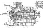
Fig. 30. Scheme of the rocket engine.
The rocket engine diagram is shown in Fig. 30. Noteworthy is the relative simplicity of this scheme compared to conventional piston aircraft engines; especially characteristic of LRE is the almost complete absence in power circuit engine moving parts. The main elements of the engine are a combustion chamber, a jet nozzle, a steam generator and a turbopump unit for fuel supply and a control system.
Fuel combustion occurs in the combustion chamber, i.e., the conversion of the chemical energy of the fuel into thermal energy, and in the nozzle, the thermal energy of the combustion products is converted into the high-speed energy of the gas jet flowing from the engine into the atmosphere. How the state of gases changes during their flow in the engine is shown in Fig. 31.
The pressure in the combustion chamber is 20–21 ata, and the temperature reaches 2,700 °C. Characteristic of the combustion chamber is a huge amount of heat that is released in it during combustion per unit time or, as they say, the heat density of the chamber. In this regard, the LRE combustion chamber is significantly superior to all other combustion devices known in the art (boiler furnaces, engine cylinders). internal combustion and others). In this case, the amount of heat released per second in the combustion chamber of the engine is enough to boil more than 1.5 tons of ice water! In order for the combustion chamber not to fail with such a huge amount of heat released in it, it is necessary to intensively cool its walls, as well as the walls of the nozzle. For this purpose, as seen in FIG. 30, the combustion chamber and nozzle are cooled by fuel - alcohol, which first washes their walls, and only then, heated, enters the combustion chamber. This cooling system, proposed by Tsiolkovsky, is also beneficial because the heat removed from the walls is not lost and returns to the chamber again (this is why such a cooling system is sometimes called regenerative). However, only external cooling of the engine walls is not enough, and cooling of their inner surface is simultaneously applied to lower the temperature of the walls. For this purpose, the walls in a number of places have small holes located in several annular belts, so that through these holes alcohol enters the chamber and nozzle (about 1/10 of its total consumption). The cold film of this alcohol, flowing and evaporating on the walls, protects them from direct contact with the flame of the torch and thus reduces the temperature of the walls. Despite the fact that the temperature of the gases washing from the inside of the walls exceeds 2500 °C, the temperature of the inner surface of the walls, as tests have shown, does not exceed 1000 °C.

Fig. 31. Change in the state of gases in the engine.
Fuel is supplied to the combustion chamber through 18 prechamber burners located on its end wall. Oxygen enters the chamber through central jets, and the alcohol leaving the cooling jacket through a ring of small nozzles around each prechamber. In this way, a sufficiently good mixing of the fuel is ensured, which is necessary for the implementation of complete combustion for that very short time while the fuel is in the combustion chamber (hundredths of a second).
The jet nozzle of the engine is made of steel. Its shape, as can be clearly seen in Fig. 30 and 31, is first a narrowing and then expanding pipe (the so-called Laval nozzle). As mentioned earlier, nozzles and powder rocket engines have the same shape. What explains this shape of the nozzle? As you know, the task of the nozzle is to ensure the complete expansion of the gas in order to obtain the highest exhaust velocity. To increase the speed of gas flow through a pipe, its cross section must first gradually decrease, which also occurs with the flow of liquids (for example, water). The velocity of the gas will increase, however, only until it becomes equal to the velocity of sound in the gas. A further increase in velocity, in contrast to a liquid, will only be possible with the expansion of the pipe; this difference between gas flow and liquid flow is due to the fact that the liquid is incompressible, and the volume of the gas increases greatly during expansion. In the throat of the nozzle, i.e., in its narrowest part, the gas flow velocity is always equal to the speed of sound in the gas, in our case, about 1000 m/s. The outflow velocity, i.e., the velocity in the outlet section of the nozzle, is 2100–2200 m/s(thus the specific thrust is approximately 220 kg sec/kg).
The supply of fuel from the tanks to the combustion chamber of the engine is carried out under pressure by means of pumps driven by a turbine and arranged together with it into a single turbopump unit, as can be seen in Fig. 30. In some engines, the fuel supply is carried out under pressure, which is created in hermetic fuel tanks with the help of some inert gas - for example, nitrogen stored under high pressure in special cylinders. Such a supply system is simpler than a pumping one, but, with enough high power engine, it turns out heavier. However, even when pumping fuel in the engine we are describing, the tanks, both oxygen and alcohol, are under some excess pressure from the inside to facilitate the operation of the pumps and protect the tanks from collapse. This pressure (1.2–1.5 ata) is created in the alcohol tank with air or nitrogen, in the oxygen tank - with vapors of evaporating oxygen.
Both pumps are centrifugal type. The turbine that drives the pumps runs on a steam-gas mixture resulting from the decomposition of hydrogen peroxide in a special steam-gas generator. Sodium permanganate, which is a catalyst that accelerates the decomposition of hydrogen peroxide, is fed into this steam and gas generator from a special tank. When a rocket is launched, hydrogen peroxide under nitrogen pressure enters the steam-gas generator, in which a violent reaction of peroxide decomposition begins with the release of water vapor and gaseous oxygen (this is the so-called "cold reaction", which is sometimes used to create thrust, in particular, in launch rocket engines). Vapor-gas mixture having a temperature of about 400 °C and pressure over 20 ata, enters the turbine wheel and then is released into the atmosphere. The power of the turbine is spent entirely on the drive of both fuel pumps. This power is not so small already - at 4000 rpm of the turbine wheel, it reaches almost 500 l. With.
Since a mixture of oxygen and alcohol is not a self-reactive fuel, some kind of ignition system must be provided to start combustion. In the engine, ignition is carried out using a special fuse, which forms a flame torch. For this purpose, a pyrotechnic fuse (a solid igniter such as gunpowder) was usually used, and a liquid igniter was less commonly used.
Rocket launch is carried out as follows. When the ignition torch is ignited, the main valves are opened, through which alcohol and oxygen enter the combustion chamber by gravity from the tanks. All valves in the engine are controlled by compressed nitrogen stored on the rocket in a battery of high-pressure cylinders. When the combustion of the fuel begins, an observer located at a distance with the help of electrical contact includes the supply of hydrogen peroxide to the steam generator. The turbine begins to work, which drives the pumps that supply alcohol and oxygen to the combustion chamber. The thrust grows and when it becomes more than the weight of the rocket (12-13 tons), the rocket takes off. From the moment the ignition flame is ignited to the moment the engine develops full thrust, only 7-10 seconds pass.
When starting, it is very important to ensure a strict order of entry into the combustion chamber of both fuel components. This is one of the important tasks of the engine control and regulation system. If one of the components accumulates in the combustion chamber (because the intake of the other is delayed), then an explosion usually follows this, in which the engine often fails. This, along with occasional interruptions in combustion, is one of the most common causes catastrophes during LRE tests.
Noteworthy is the negligible weight of the engine compared to the thrust it develops. When the engine weight is less than 1000 kg thrust is 25 tons, so that the specific gravity of the engine, i.e., the weight per unit of thrust, is only
![]()
For comparison, we indicate that a conventional piston aircraft engine running on a propeller has a specific gravity of 1–2 kg/kg, i.e., several tens of times more. It is also important that the specific gravity of a rocket engine does not change with a change in flight speed, while the specific gravity of a piston engine increases rapidly with increasing speed.
LRE for rocket aircraft

Fig. 32. Project LRE with adjustable thrust.
1 - mobile needle; 2 - mechanism for moving the needle; 3 - fuel supply; 4 - oxidant supply.
The main requirement for an aircraft liquid-propellant engine is the ability to change the thrust it develops in accordance with the flight modes of the aircraft, up to stopping and restarting the engine in flight. The simplest and most common way to change the thrust of an engine is to regulate the supply of fuel to the combustion chamber, as a result of which the pressure in the chamber and thrust change. However, this method is unfavorable, since with a decrease in pressure in the combustion chamber, which is lowered in order to reduce thrust, the proportion of thermal energy of the fuel that passes into the high-speed energy of the jet decreases. This results in an increase in fuel consumption by 1 kg thrust, and consequently, by 1 l. With. power, i.e., the engine starts to work less economically. To reduce this shortcoming, aircraft rocket engines often have two to four combustion chambers instead of one, which makes it possible to turn off one or more chambers when operating at reduced power. Thrust control by changing the pressure in the chamber, i.e., by supplying fuel, is retained in this case as well, but is used only in a small range up to half the thrust of the chamber being switched off. The most advantageous way to control the thrust of a liquid-propellant rocket engine would be to change the flow area of its nozzle while reducing the fuel supply, since in this case a decrease in the per second amount of escaping gases would be achieved while maintaining the same pressure in the combustion chamber, and, hence, the exhaust velocity. Such regulation of the nozzle flow area could be carried out, for example, using a movable needle of a special profile, as shown in Fig. 32, depicting the design of a liquid-propellant rocket engine with thrust regulated in this way.
In FIG. 33 shows a single-chamber aircraft rocket engine, and Fig. 34 - the same rocket engine, but with an additional small chamber, which is used in cruise flight when little thrust is required; the main camera is turned off completely. On maximum mode both chambers work, and the large one develops a thrust of 1700 kg, and small - 300 kg, so the total thrust is 2000 kg. The rest of the engines are similar in design.
The engines shown in Fig. 33 and 34 operate on self-igniting fuel. This fuel consists of hydrogen peroxide as the oxidizer and hydrazine hydrate as the fuel, in a weight ratio of 3:1. More precisely, the fuel is a complex composition consisting of hydrazine hydrate, methyl alcohol and copper salts as a catalyst that ensures a fast reaction (other catalysts are also used). The disadvantage of this fuel is that it causes corrosion of engine parts.
The weight of a single chamber engine is 160 kg, the specific gravity is
![]()
per kilogram of thrust. Engine length - 2.2 m. The pressure in the combustion chamber is about 20 ata. When operating at the minimum fuel supply to obtain the least thrust, which is 100 kg, the pressure in the combustion chamber decreases to 3 ata. The temperature in the combustion chamber reaches 2500 °C, the gas flow rate is about 2100 m/s. Fuel consumption is 8 kg/s, and the specific fuel consumption is 15.3 kg fuel per 1 kg thrust per hour.

Fig. 33. Single-chamber liquid-propellant rocket engine for a rocket aircraft

Fig. 34. Two-chamber aircraft rocket engine.

Fig. 35. Scheme of fuel supply in an aviation rocket engine.
The scheme of fuel supply to the engine is shown in Fig. 35. As in a rocket engine, the supply of fuel and oxidizer stored in separate tanks is carried out at a pressure of about 40 ata impeller driven pumps. A general view of the turbopump unit is shown in Fig. 36. The turbine runs on a steam-gas mixture, which, as before, is obtained as a result of the decomposition of hydrogen peroxide in a steam-gas generator, which in this case is filled with a solid catalyst. Before entering the combustion chamber, the fuel cools the walls of the nozzle and the combustion chamber, circulating in a special cooling jacket. The change in the fuel supply necessary to control the engine thrust during the flight is achieved by changing the supply of hydrogen peroxide to the steam-gas generator, which causes a change in the speed of the turbine. Maximum number turbine speed is 17,200 rpm. The engine is started using an electric motor that drives the turbopump unit.

Fig. 36. Turbopump unit of an aviation rocket engine.
1 - gear drive from the starting electric motor; 2 - pump for the oxidizer; 3 - turbine; 4 - fuel pump; 5 - turbine exhaust pipe.
In FIG. 37 shows a diagram of the installation of a single-chamber rocket engine in the rear fuselage of one of the experimental rocket aircraft.
The purpose of aircraft with liquid-propellant engines is determined by the properties of liquid-propellant rocket engines - high thrust and, accordingly, high power at high flight speeds and high altitudes and low efficiency, i.e., high fuel consumption. Therefore, rocket engines are usually installed on military aircraft - interceptor fighters. The task of such an aircraft is, upon receiving a signal about the approach of enemy aircraft, to quickly take off and gain a high altitude at which these aircraft usually fly, and then, using their advantage in flight speed, impose an air battle on the enemy. The total duration of the flight of an aircraft with a liquid-propellant engine is determined by the fuel supply on the aircraft and is 10-15 minutes, so these aircraft can usually perform combat operations only in the area of their airfield.

Fig. 37. Scheme of the installation of rocket engines on the plane.

Fig. 38. Rocket fighter (view in three projections)
In FIG. 38 shows an interceptor fighter with the LRE described above. The dimensions of this aircraft, like other aircraft of this type, are usually small. The total weight of the aircraft with fuel is 5100 kg; the fuel reserve (over 2.5 tons) is only enough for 4.5 minutes of engine operation at full power. Maximum flight speed - over 950 km/h; the ceiling of the aircraft, i.e. the maximum height that it can reach, is 16,000 m. The rate of climb of an aircraft is characterized by the fact that in 1 minute it can rise from 6 to 12 km.

Fig. 39. The device of a rocket aircraft.
In FIG. 39 shows the device of another aircraft with a rocket engine; this is an experimental aircraft built to achieve flight speeds in excess of the speed of sound (i.e. 1200 km/h at the ground). On the plane, in the rear of the fuselage, an LRE is installed, which has four identical chambers with a total thrust of 2720 kg. Engine length 1400 mm, maximum diameter 480 mm, weight 100 kg. The stock of fuel on the plane, which is used as alcohol and liquid oxygen, is 2360 l.

Fig. 40. Four-chamber aircraft rocket engine.
The external view of this engine is shown in Fig. 40.
Other applications of LRE
Along with the main use of liquid-propellant rocket engines as engines for long-range missiles and rocket aircraft, they are currently used in a number of other cases.
Enough wide application received liquid-propellant rocket engines as engines of heavy rocket projectiles, similar to those shown in Fig. 41. The engine of this projectile can serve as an example of the simplest rocket engine. Fuel (gasoline and liquid oxygen) is supplied to the combustion chamber of this engine under the pressure of neutral gas (nitrogen). In FIG. 42 shows a diagram of a heavy rocket used as a powerful anti-aircraft projectile; the diagram shows dimensions rockets.
LRE are also used as starting aircraft engines. In this case, a low-temperature hydrogen peroxide decomposition reaction is sometimes used, which is why such engines are called "cold".
There are cases of using LRE as boosters for aircraft, in particular, aircraft with turbojet engines. In this case, fuel supply pumps are sometimes driven from the turbojet engine shaft.
Liquid-propellant rocket engines are also used, along with powder engines, for launching and accelerating aircraft (or their models) with ramjet engines. As you know, these engines develop very high thrust at high flight speeds, high speeds of sound, but do not develop thrust at all during takeoff.
Finally, one more application of LRE, which has recently taken place, should be mentioned. To study the behavior of an aircraft at high flight speeds approaching the speed of sound and exceeding it, serious and expensive research work is required. In particular, it is required to determine the resistance of aircraft wings (profiles), which is usually carried out in special wind tunnels. To create conditions in such tubes that correspond to the flight of an aircraft at high speed, it is necessary to have power plants very high power to drive fans that create flow in the pipe. As a result, the construction and operation of tubes for testing at supersonic speeds require huge costs.
Recently, along with the construction of supersonic tubes, the task of studying various profiles of the wings of high-speed aircraft, as well as testing ramjet engines, by the way, is also being solved with the help of liquid-propellant

Fig. 41. Rocket projectile with rocket engine.
engines. According to one of these methods, the investigated profile is installed on a long-range rocket with a liquid-propellant rocket engine, similar to the one described above, and all readings of instruments that measure the resistance of the profile in flight are transmitted to the ground using radio telemetry devices.

Fig. 42. Scheme of the device of a powerful anti-aircraft projectile with a rocket engine.
7 - combat head; 2 - cylinder with compressed nitrogen; 3 - tank with oxidizer; 4 - fuel tank; 5 - liquid-propellant engine.
According to another method, a special rocket trolley is being built, moving along rails with the help of a liquid-propellant rocket engine. The results of testing a profile installed on such a trolley in a special weight mechanism are recorded by special automatic devices also located on the trolley. Such a rocket cart is shown in Fig. 43. Length rail track can reach 2-3 km.

Fig. 43. Rocket trolley for testing aircraft wing profiles.
From the book Identifying and Troubleshooting on Your Own in a Car author Zolotnitsky VladimirThe engine is unstable in all modes Malfunctions of the ignition system Deterioration and damage to the contact carbon, its hanging in the cover of the ignition distributor. Current leakage to ground through soot or moisture on the inner surface of the cover. Replace pin
From the book Battleship "PETER THE GREAT" authorEngine runs erratically at low RPM crankshaft or mute on Idling Carburetor malfunctions Low or high level fuel in the float chamber. Low level- pops in the carburetor, high - pops in the muffler. Exhaust
From the book Battleship "Navarin" author Arbuzov Vladimir VasilievichThe engine runs normally at idle, but the car accelerates slowly and with "dips"; poor engine acceleration Malfunctions of the ignition system The gap between the contacts of the breaker is not adjusted. Adjust Angle closed state contacts
From the book Planes of the World 2000 02 author author unknownThe engine "troit" - one or two cylinders do not work Malfunctions of the ignition system Unstable operation of the engine at low and medium speeds. Increased consumption fuel. The smoke exhaust is blue. Somewhat muffled periodically emitted sounds, which are especially good
From the book World of Aviation 1996 02 author author unknownWhen suddenly opened throttle valves the engine runs intermittently Malfunctions of the gas distribution mechanism Valve clearances are not adjusted. Every 10 thousand kilometers (for VAZ-2108, -2109 after 30 thousand km) adjust the valve clearances. With reduced
From the book We service and repair the Volga GAZ-3110 author Zolotnitsky Vladimir AlekseevichThe engine runs unevenly and unstable at medium and high crankshaft speeds Malfunctions of the ignition system Misalignment of the gap of the breaker contacts. To fine-tune the gap between the contacts, measure not the gap itself, and even the old-fashioned
From the book Rocket Engines author Gilzin Karl AlexandrovichApplications HOW "PETER THE GREAT" WAS ORGANIZED 1 . Seaworthiness and maneuverability The whole complex of tests carried out in 1876 revealed the following seaworthiness. The safety of the ocean navigation of "Peter the Great" did not inspire fear, and its inclusion in the class of monitors
From the book Jet Engines author Gilzin Karl AlexandrovichHow the battleship "Navarin" was arranged width 20.42, design draft 7.62 m bow and 8.4 stern and recruited from 93 frames (spacing 1.2 meters). The frames provided longitudinal strength and full
From the book History of Electrical Engineering author Team of authorsSu-10 - the first jet bomber of the OKB P.O. Sukhoi Nikolay GORDIUKOVAfter the Second World War, the era of jet aviation began. The re-equipment of the Soviet and foreign air forces for fighters with turbojet engines took place very quickly. However, the creation
From the author's book From the author's bookThe engine runs erratically at low crankshaft speed or stalls at idle Fig. 9. Carburetor adjusting screws: 1 - operational adjustment screw (quantity screw); 2 - mixture composition screw, (quality screw) with restrictive
From the author's bookThe engine is unstable in all modes
From the author's bookHow a powder rocket engine is arranged and works structural elements gunpowder, like any other rocket engine, are the combustion chamber and nozzle (Fig. 16). Due to the fact that the supply of gunpowder, as well as any solid fuel in general, into the chamber
From the author's bookFuel for a liquid-propellant engine The most important properties and characteristics of a liquid-propellant engine, and indeed its design, primarily depend on the fuel used in the engine. The main requirement for fuel for liquid-propellant rocket engines is
From the author's bookChapter Five Pulsating Jet Engine high speeds flight seems strange, perhaps even unbelievable. The entire history of aviation still speaks of the opposite: the struggle
From the author's book6.6.7. SEMICONDUCTOR DEVICES IN ELECTRIC DRIVE. SYSTEMS THYRISTOR CONVERTER - ENGINE (TP - D) AND CURRENT SOURCE - ENGINE (IT - D)