Timing chain drive Hyundai Accent is part of the gas distribution mechanism and participates in the transmission of torque from the crankshaft to the camshaft. The chain can connect them directly or participate in the work indirectly, for example, combining camshafts with each other, if there are two of them, while functional purpose it remains unchanged.
Monitoring the condition of the timing chain, replacing the "damper" and tensioners, is part of the planned Maintenance car and playing important role in engine operation vehicle. It is necessary to monitor the condition of the gas distribution system regularly, as this directly affects the vehicle's power, gas supply sensitivity and fuel consumption.


In most engines of older car models, chains with roller links were used to transmit torque, often the components went in two or three rows, this made the timing chain a very reliable, almost eternal mechanism that did not need constant maintenance. Often the car passed up to 300,000 km. and the chain of the mechanism received only lateral play, and the worst thing that could happen to the gas distribution mechanism was the jumping of links, breaks were extremely rare. Over time, the trend in building cars has become production price, efficiency, environmental friendliness and the weight of the car engine, which affects its power. Under these conditions, manufacturers began to strive to replace the timing chain with a lighter, cheaper and easier to maintain timing belt. And those motors in the design of which the chains were preserved, the roller components were replaced with light plate links, more reliable than timing belts, but still not as strong as roller chains.
Timing chain Hyundai mechanism Accent has a number of features that radically distinguish it from the timing belt.
1. The chain is a durable mechanism, it wears out much longer than the timing belt, breaks occur, but much less often than for belt-driven engines.
2. An open circuit of the gas distribution mechanism occurs quite rarely, which means an engine breakdown that requires an expensive overhaul, does not occur frequently.
3. Timing chains are quite noisy, but when modern level soundproofing the car, this parameter becomes not very important.
4. When the chain wears out, its backlash and transverse runout occur, this indicates the need to replace the old chain with a new one. Since the part is metal, sagging and transverse runout is accompanied loud noise, not to notice and not to attach importance to which is simply impossible. Noise under the hood will be the first "call" indicating the need for vehicle maintenance.
5. The main disadvantage of replacing the Hyundai Accent timing chain is that it is located inside the cylinder block and it is quite difficult to assess its condition without training and experience. In addition, dismantling and replacement, with such a device, is a long and laborious process, and therefore expensive.
6. Tensioners and dampers are involved in the operation of the timing chain - these are consumable parts that wear out quickly and need more frequent replacements than the timing chain itself.
1. For timing chains, with full serviceability, a natural course is observed, which is compensated by tensioners when oil pressure is applied. A malfunction is considered to be a strong lateral runout of the timing chain, which appears when the links are stretched. It is possible to determine the actual degree of chain stretching only with a qualified inspection of the gas distribution mechanism.
2. Backlash is the direct stretch of the chain, which is observed when long-term operation, can lead to jumping of the chain links and malfunction of the gas distribution mechanism, this leads to a decrease in the sensitivity of the motor when the gas pedal is pressed and an increase in fuel consumption.
3. An open timing chain Hyundai Accent - is the most dangerous damage to the engine, in the event chain drive motor is not common, but it has a place to be. In the event of such a malfunction, the camshaft ceases to be associated with crankshaft and can stop completely arbitrarily in a position in which any of the valves of the gas distribution mechanism is open. In this case, the piston, moving up, may collide with the valve, which will lead to its deformation and the car engine will face serious repairs. It should be noted that an open timing chain does not occur unexpectedly, it is almost always accompanied by changes in the operation of the vehicle, a decrease in its power, a change in gasoline consumption and the occurrence of extraneous noise.
To prevent and prevent the operation of the gas distribution mechanism, it is necessary to periodically troubleshoot the timing chain, this will save the car engine from breakdown, warn premature wear engine and increase its lifespan.


1. Operation Hyundai car Accent in extreme conditions. Frequent driving on dirt roads, towing trailers, heavy loads, driving at high speeds leads to an increase in the load on the crankshaft, spinning it up to maximum speed which stretches the timing chain.
2. Since the timing chain is located inside the cylinder block, it is completely washed by engine oil and, as a result, is very sensitive to its quality. In the case of using high-quality synthetic oil, which has in its composition specialized detergent additives, the service life of the timing chain is greatly increased
3. The timing chain involves parts that regulate the chain tension, they are consumables and need to be replaced periodically. During the maintenance of the car, it is necessary to check the degree of wear of the tensioner and the damper, untimely replacement these parts can cause the chain to stretch and jump links.
1. Increasing the consumption of gasoline by car;
2. Reducing engine power; 3. The appearance of clanging and noise under the hood of the car with the engine running;
4. A complete stop of the car on the go, when you try to start the engine does not start, and the starter rotates easier than usual;
5. Unstable work Hyundai engine Accent on Idling and in motion;
6. The occurrence of shots in the injector receiver and exhaust pipe.
All these problems may indicate a shift in the valve timing and loosening of the chain tension. If you notice one or more signs of this list on your car, immediately contact the service station for an inspection.


The frequency of replacement of any Supplies for Hyundai Accent vehicles depends on the driving style and mode of operation of the vehicle. With extreme driving style and aggressive use of the vehicle, it is necessary to replace the timing chain as it becomes loose and worn.
IN normal conditions operation, it is necessary to replace the timing chain as planned, every 100 - 150,000 km. run. If your car has an analog belt, it must be replaced a little earlier than the time recommended by the vehicle manufacturer.
Trust your car only to professional specialists who are able to competently troubleshoot the timing chain, evaluate lateral runout and play, replace and adjust the work of tensioners, “damper” of the chain drive and replace the Hyundai Accent timing chain.
- Drain the oil and remove the oil pan. If the crankcase is firmly stuck, then carefully wring it out with a screwdriver, being careful not to damage the seal location.
- Remove the V-belt.
- Loosen pulley V-belt transmission crankshaft and remove it. To prevent the crankshaft from rotating, engage 4th gear and have an assistant apply the brake. Remove the gear cover. Do not damage the O-ring while doing this.
- Crank the engine until the crankshaft sprocket mark and camshaft sprocket mark are exactly facing each other.
- In the workshop for fixing chain tensioner used special tool(Mot. 761). In the absence of a special tool, twist the tensioner and spring with wire until the chain is free from the tensioner.
- Loosen both fixing bolts and unscrew them.
- Remove the chain tensioner.
- Bend the lock washer of the central bolt of the chain sprocket camshaft and unscrew the bolt.
- Remove the camshaft sprocket along with the drive chain.
- Never rotate the crankshaft and camshaft after this!
- Remove the crankshaft chain sprocket using a standard puller. To avoid damage to the threads, screw a suitable bolt in the middle into the end of the crankshaft.
- Remove the safety key from the crankshaft.
- Before assembling, clean the surfaces of the unit and the cover, which ensure the tightness of the motor.
- Insert the safety key into the groove of the crankshaft.
- Screw a suitable bolt into the end of the crankshaft and press the sprocket onto the crankshaft using a spacer sleeve (25 mm diameter) and a nut with a large washer.
- Fit the camshaft chain sprocket with drive chain. At the same time, the marks on the sprockets of the distributive and crankshaft must look exactly at each other (sprocket marks must be on the same imaginary straight line drawn between the centers of the axes of the camshaft and crankshaft).
- Screw in the camshaft chain sprocket bolt with a new lock washer and tighten to 30 Nm.
- Bend the end of the lock washer.
- Install the chain tensioner and remove the wire with which it was fixed.
- Install the gear covers with new gasket. To avoid slipping, fix the gasket in the lid with silicone paste.
- Tighten the bolts evenly so as not to damage the gasket.
- Clean the surfaces of the oil pan and engine element; degrease them with a solvent.
- Apply a 3 mm thick coat of sealant to the bearings (flywheel side) on the surface of the oil pan in contact with the engine. In this case, the sealant must not get into the holes for the bolts. Apply a little more sealant to the 4 corners of the oil pan near the main bearings.
- In the main bearing - where the sealant was not applied - install a new rubber gasket.
- If necessary, screw 4 suitable sawn-off bolts as centering pins into the motor housing.
- Install the oil pan and secure with 8-10 Nm bolts.
- Then replace the centering pins with bolts and tighten them to 8-10 Nm.
- Put on the crankshaft pulley with a groove and tighten the bolts (bolts 40 mm long with a force of 80 Nm; screw 45 mm long with a force of 110 Nm).
- Put on the V-belt and tension it, see chapter Cooling system.
- Fill the engine with oil and then test drive check for oil leaks.
PROCEDURE
1. Install hydraulic valve clearance compensators.
2. Install the chain on sprockets camshafts as shown in the figure.

3. Before installing, apply a thin layer of clean engine oil to all sliding surfaces of the camshafts. Install the camshafts.

4. Install the camshaft bearing caps. Check the identification marks that identify the intake or intake camshafts. exhaust valves.
Intake camshaft: I
Exhaust camshaft: E

Tightening torque: 12-14 Nm

6. Lubricate with engine oil the working edges and the outer surface of the sealing ring and with a special tool 09221-21000 install the sealing ring on the front of the camshaft.
By blows of a hammer on the special adaptation establish a sealing ring against the stop in a socket.

Tightening torque: 80–100 Nm
8. Align installation mark camshaft and the alignment mark of the crankshaft pulley with pointers, while the piston of the 1st cylinder will be at TDC on the compression stroke.

9. Establish a cover of a head of cylinders and tighten bolts of fastening of a cover the demanded moment.
Tightening torque: 8-10 Nm
10. Install high voltage wires, ignition coils and center cover.
11. Install toothed belt and tighten the toothed belt tensioner.
12. Establish casings of a gear belt.

Other on site:
Driving in the rain
Rain and wet roads make driving dangerous, especially if you are not prepared for slippery surfaces. Pay attention to a few tips when driving in the rain: Heavy rain make it hard to see...
Removing and installing loudspeakers
REMOVAL Door loudspeakers PERFORMANCE ORDER 1. Carefully prying off, remove the decorative loudspeaker grille. 2. Remove the fixing screws and release the loudspeaker from its seat...
intake manifold and airbox
An inlet collector and the air chamber 1 – an inlet collector; 2 - bolt, 15–20 N m; 3 - throttle assembly; 4 - bolt, 15–20 N m; 5 - gasket; 6 - fuel line; 7 - air compensation ...
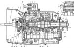
Gas distribution mechanism
| 1 - camshaft sprocket that controls the exhaust valves, 2 - copper installation elements on the side chain surface, 3 - timing chain drive, 4 - side chain damper, 6 - leading sprocket, 5 - crankshaft, 7 - drive chain tensioner oil pump, 8 - oil pump drive chain, |
9 – oil pump rotor, 10 - pressure reducing valve, 11 - oil supply channel to the hydraulic pusher of the chain tensioner, 12 – hydraulic pusher of the chain tensioner, 13 - chain tensioner sprocket, 14 – chain tensioner lever, 15 - camshaft sprocket that controls intake valves, 16 - upper chain guide |
Removing the axle tensioner DOHC engine timing chain
Location of the hydraulic pusher of the tensioner of the drive chain of the DOHC engine timing system
DOHC Engine Timing Installation
| PROCEDURE | ||||||||||||||||||||||||||||||||||||||||||||||||||||||||||||
|
||||||||||||||||||||||||||||||||||||||||||||||||||||||||||||
Examination
Check the timing chain, sprockets and chain tensioner for wear and damage. If the plastic sprocket of the chain tensioner is worn out, the entire tensioner assembly must be replaced, since sprockets are not supplied separately.
Hydraulic Pusher Chain Tensioner
The position of the sprocket installation marks corresponding to the installation of the piston of cylinder 1 in the upper dead center in the compression stroke
Special tool made of 2.5 mm wire to release the plunger of the chain tensioner pusher
Warning
There are copper elements on the timing chain that are used to properly position the timing mechanism when installing the chain.
Installation| PROCEDURE | ||||||||||||||||||||||||||||||||||||||||||||||||||||||
| ||||||||||||||||||||||||||||||||||||||||||||||||||||||
You will need: wrenches "for 14", "for 17", "for 19", socket heads "for 14", "for 17", "for 19", extension cord, wrench, screwdriver with a flat blade.
1. Disconnect a wire from the minus plug of the storage battery.
2. Remove the cylinder head cover (see "Replacing the cylinder head cover gasket", page 69),
3. Remove the engine mudguard (see "Removing and installing the engine mudguard", page 64).
4. Set the piston of the 1st cylinder to the TDC position of the compression stroke (see "Setting the piston of the first cylinder to the TDC position of the compression stroke", p. 68).
5. Drain the engine oil from the crankcase (see "Changing the engine oil and oil filter", With. 84).
6. Remove the upper bracket of the right support power unit(see "Replacing the right suspension support of the power unit", p. 65),
7. Remove the drive belt auxiliary units(See "Replacing the accessory drive belt", page 197).
8. Turn out a bolt of the top fastening of the pump of the hydraulic booster …
9. ... and move the pump aside.
10. Turn out a bolt of fastening of a tensioner of a belt of a drive of auxiliary units (a bolt with a reverse carving) …
11. ... and remove the tensioner.
12. Turn out four bolts of fastening of the bottom arm of the right support to the engine …
13. ... and remove the bracket.
14. Turn out a bolt of fastening of an auxiliary roller of a belt of a drive of auxiliary units and remove a roller.
15. Remove the water pump (see "Replacing the water pump", page 91).
16. Holding the crankshaft pulley from turning with a special tool, unscrew the pulley mounting bolt.
17. Remove the pulley from the crankshaft.
18. Remove the generator (see "Removing and installing the generator", p. 197).
19. Turn out two bolts of fastening of an arm of the generator …
20. ... and remove the bracket.
21. Turn out fourteen bolts of fastening of a cover of the gas-distributing mechanism (fig. 5.11) …
Rice. 5.11. Arrangement of bolts of fastening of a cover of a chain of a drive of the gas-distributing mechanism
22. ... and remove the cover.
23. special fixture or use a screwdriver to depress the tensioner shoe and fix the tensioner with the pin.
24. Turn out two bolts of fastening of a tensioner...
25. ...and take it off.
26. Slightly rotate the exhaust camshaft clockwise ...
27. ... and remove the chain from the camshaft gears and from the crankshaft gear.
28. Install the chain in reverse order on the marks on the camshaft gears and on the chain (colored links), making sure that the locating pin on the crankshaft is at the top.
29. Clean the mating surfaces of the tensioner and cylinder block from the old sealant.
30. Apply sealant to the mating surfaces of the timing chain cover with a roller 3–5 mm thick.
31. Install the chain tensioner and remove the pin from it.
32. Check the alignment of the marks on the gears of the camshafts and on the timing chain, as well as the position of the crankshaft, the locating pin of which must be at the top.
33. Apply sealant to the mating surfaces of the timing chain cover with a roller 3–5 mm thick, install the cover, screw in and tighten evenly, in several steps, 10 mm bolts with a torque of 9.8–11.8 Nm, and 12 mm bolts with a torque of 18.6–23.5 Nm.
34. Install all other parts in the reverse order of removal.
Helpful advice
Every time you remove the timing chain cover, replace the crankshaft oil seal (see "Replacing the crankshaft oil seals", page 72).