) refer to guiding equipment and serve to control the direction of flow compressed air. Control is carried out when switching through changes in the connection scheme of the internal channels of the distributor with inlet and outlet connecting holes. The functionality of the valves is determined by the following parameters: number of operating channels, number of switching positions, normal position, control method and capacity.
Each of possible schemes The distributor's internal connections are indicated by a square showing the compressed air flow paths (fig. 1).
Fig.1. The principle of forming a symbolic graphic designation of distributors
In Fig.1, the movable locking element can occupy two discrete positions corresponding to two states of the pneumatic distributor: 1) “air passage closed”; 2) "air passage is open". In this case, the locking element can switch between two lines: 1) power line (input); 2) consumer line (output). In this regard, such distributors are called two-line and two-position, which is reflected in its conditional graphic designation.
To determine the characteristics of distributors for switching channels, it is used digital designation in the form of a fraction, where the numerator corresponds to the number of switched lines, and the denominator - to the number of possible positions. In accordance with this principle, the device in Fig. 1 will be called a 2/2-air distributor.
On circuit diagrams distributors are depicted in such a way that external pneumatic lines (communication lines) go to the square that indicates the initial position of the distributor.
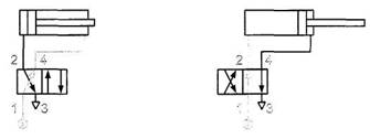
To control single-acting pneumatic cylinders, a pneumatic distributor is used, which has the ability to switch the supply, consumer and exhaust lines. (Fig. 2).
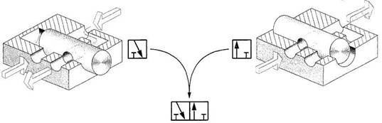
Rice. 2 Model and graphic designation of 3/2-way valve
 The 3/2-pneumatic valve commutates three working lines (Fig. 4): 1 - supply line, 2 - consumer line and 3 - exhaust line. In this case, the distributor itself has two positions: the supply is blocked, the consumer is connected to the exhaust; compressed air enters the consumer, the exhaust is blocked.
Fig.3. Control of a single-acting pneumatic cylinder with a 3/2-way valve
To control double-acting pneumatic cylinders, more complex distributors are required, since in this case it is necessary to ensure the redistribution of compressed air flows between the two working cavities of the actuator and the discharge of exhaust air from them (Fig. 5.).
Rice. 4.. Double-acting pneumatic cylinder control with 4/2-way valve
The four-way two-position pneumatic valve (4/2-air valve) has the ability to alternately supply compressed air from the line high pressure 1 through working channels 2 or 4 into one of the cavities of the pneumatic cylinder while connecting the other to the atmosphere 3.
In practice, 5/2-pneumatic distributors are most often used to control double-acting pneumatic cylinders (Fig. 5).
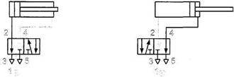
Rice. 5. Double-acting pneumatic cylinder control with 5/2-air valve
Despite the more complex graphic designation of 5/2-pneumatic valves, their design is simpler, and the functionality is somewhat wider than that of 4/2-pneumatic valves, which is associated with the presence of not one, but two exhaust channels 3 and 5, separate for each working cylinder cavity.
To solve more complex problems of pneumatic cylinder control, three-position distributors are used, which have wider functionality. This is due to the fact that such distributors can carry out not two, but three options for switching pneumatic lines.
The numbering of the channels used in the diagrams is not random, but corresponds to the standards according to which a certain alphabetic or numeric indexing is used to designate the working and control channels of pneumatic devices and devices (Table 1).
Given in table. 1 indexing is sometimes affixed to pneumatic circuit diagrams. Marking the connecting holes in the housings of pneumatic devices with these indices allows you to correctly install and mount pneumatic systems.
Switching of pneumatic distributors from one position to another is achieved by moving their ZRE by external control actions.
Distributor control can be manual, foot, mechanical; pneumatic; electric; combined.
Indexing (marking) of lines (connecting holes) of pneumatic devices Tab. 1.
Same base model the pneumatic distributor can have various control elements
When reading the principle pneumatic diagrams, it must be borne in mind that the control signal supplied from the left switches the valve to the position indicated in the conditional graphic designation of this apparatus by the left square, and the signal supplied from the right to the position indicated by the right square.
Unlike working pneumatic lines, pneumatic control lines are designated not by single digits, but by double digits.

Indexing of pneumatic control lines
The first digit in such a two-digit designation coincides with the index of the supply line, and the second - with the index of the consumer line, into which compressed air will flow after the control signal is applied. So, index 12 (Fig. 6, a, b) on the control line means that if there is a pneumatic control signal in this line, compressed air will flow to the consumer through the working line 2. To switch the consumer line 4 with power line 1, the control signal must be applied to line 14 (Fig. 6, c).
Pneumatic distributors 3/2 are special devices, with the help of which such procedures for managing air flows as: starting, stopping and redirecting are performed. Distributors are piston devices that support electromagnetic control. Devices of this type are implemented with a nominal bore Dy=6 or 12 and are designed for operating pressure in the pneumatic system within values from 0.1 MPa to 1 MPa.
Principle of operation and device
The functioning of 3/2 distributors lies in the fact that the valve, the main working element, is actuated by means of a membrane. Executive signal from electromagnetic system it is supplied precisely to the membrane, with the help of which the force is transmitted to displace the piston-type valve. In the process of moving the valve, the opening or closing of the holes through which air currents. The return movement of the valve to its original position is carried out under the action of elastic forces of compression of the return spring. Devices of this type are effectively used in pneumatic systems ah, which have two or three channels. The difference between distributors of this type is that they do not need to be lubricated - they work without friction, so lubrication is not required. Since the valve mechanism of the distributor is very sensitive to the value of the pressure on the membrane and the working section, it is recommended for use in schemes of pneumatic systems with one stable position.
terms of Use
The devices are manufactured in case design, which guarantees the IP65 level of protection against moisture and dust. This provides for the possibility of distributors operation in rather wide temperature ranges: -10ºС…+40ºС or -10ºС…+60ºС (depending on version). As a working medium, technical air is used in its usual form or in an oily medium. The fixed network can be used to power the 3/2 distributors alternating current. The procedure for controlling the operation of switchgears is implemented through pulse signals (given remotely) or in manual mode management.
PURPOSE OF THE PNEUMATIC VALVE
The VESTA E and V series pneumatic distribution valves are designed to control the supply of compressed air to various equipment and systems using pneumatic executive mechanisms(cylinders, valves with pneumatic control, etc.). When choosing a series of pneumatic valve, it is recommended to give preference to the new K-series, which has improved characteristics and more compact dimensions at the same cost.
DESIGN FEATURES OF THE PNEUMATIC VALVE
E series valves with G1/8”, G1/4” and G1/2” connections are available with 3/2, 5/2 or 5/3 functions.
The choice of high quality materials contributes to the achievement of good valve performance even under severe conditions.
The main elements of the valve - pneumatic distributor are: aluminum valve body; nickel-plated piston; solenoid; inductor.
The nickel-plated piston is made of light aluminum alloy to make its surface smooth and improve resistance to aggressive substances. The special shape of the valve makes it possible to achieve high airflow rates (see fig. D), and with self-lubricating edges rubber seals(see fig. B) reduces internal friction (see fig. C) and ensures a long service life of the valve.
Diverter valves with G1/8”, G1/4” and G1/2” connections can be operated without lubrication (see fig. E).
Pneumatic valves of the E series are equipped with manual control.
 |
 |
|
 |
 |
 |
OPERATING PRINCIPLE
OPERATING PRINCIPLE OF AIR DISTRIBUTION VALVES
Consider the principle of operation of the pneumatic distributor using the example of the E52W1S018-02400 valve with 5/2 function. This valve has 5 connections and 2 possible states. Connections (see fig. 1 and fig. 2): 1 - inlet port for supplying a controlled air flow; 2 3 4 - outlet port for air supply to the necessary part of the pneumatic system, or to the atmosphere; 5 - connection to the atmosphere to relieve pressure from the pneumatic system through connection 2;CONTROL VALVE STATES
- State 1(see fig. 1): no voltage applied to the coil. In this state, the input port 1 connected to output port 2 , and the output port 4 5 3 not involved.
- State 2(see fig. 2): voltage is applied to the coil. In this state, the input port 1 connected to output port 4 , and the output port 2 connected to the atmosphere through a port 3 . At the same time, the connection with the atmosphere 5 not involved.
Transition from States 1 V State 2 This is done by applying voltage to an inductor, which pulls in a solenoid, which in turn changes the position of the piston.
Transition from States 2 V State 1 is carried out when the voltage is removed from the inductor, due to spring or pneumatic return.
Function 3/2
Valves - pneumatic distributors with function 3/2 differ from distribution valves of function 5/2 in the absence of ports 5 and 4, i.e. they have 3 connections and 2 possible states.
Function 5/3
5/3 function directional control valves differ from 5/2 function directional control valves by having two inductors, so they have 3 possible states. The two states are similar to 5/2 directional valves, and the third state may be different depending on the design of the directional control valve. In any case, when choosing a valve - a pneumatic distributor, one should proceed from the pneumatic scheme of its operation.
Page 1
Pneumatic distributor supplying air or gas into the cavity power cylinder valve 7 is equipped with an electromagnet, which, in the presence of voltage, maintains the distributor spool in the closed position. In the event of an emergency de-energization of the facility, as well as signals from a decrease in pressure or flow of the locking water, the power supply to the electromagnet is removed, the distributor spool moves to the open position under the action of the spring, and the air from the cylinder 9 opens the valve. Gas from cylinders 3 enters hydraulic cylinders through reducers and pneumatic valves and displaces water through valves into the distributing manifold of locking water. If within one minute after the opening of the pneumatic valves the parameters of the blocking water have not been established, the pumps are automatically switched off and the AGS provides power to their seals for the run-out time.
Pneumatic distributors are distinguished by a wide variety structural design. On fig. 2.118 shows pneumatic spool valves type 5 / 2 with in a different way management. This changes the direction of the compressed air flow. Distributors with manual toggle switch (Fig. 2.118, b) and push-button (Fig. 2.118, c) control operate in the same way.
The pneumatic distributor, which supplies air or gas to the cavity of the power cylinder of the valve 7, is equipped with an electromagnet, which, in the presence of voltage, maintains the distributor spool in the closed position. Gas from cylinders 3 enters hydraulic cylinders through reducers and a pneumatic valve and displaces water through valves into the distributing collector of locking water. If within 1 min after the opening of the pneumatic valve the parameters of the blocking water are not restored, the pumps are automatically switched off and the AGS provides power to their seals for the run-out time.
A three position flat spool pneumatic valve is shown in Fig. The spool 4 with annular grooves, one large a and the other small b, enclosed between the body / to the cover 2, sealed with a gasket 3, is pressed against the cover by a spring. Air is supplied to channel c from the air collector, and air is bled into the atmosphere through hole e.
A manually operated pneumatic valve with a cam-operated valve mechanism, different from those discussed above, is shown in FIG.
In pneumatic valves with combined control, the primary signal is electrical, and the secondary signal is pneumatic. When voltage is applied to the electromagnets, the valves or spools of the pneumatic servomechanism are actuated, which communicates the movement to the main distribution body. In this case, spool and valve distribution is used.
As can be seen, the use of a serial pneumatic distributor makes it possible to abandon the handicraft production of an electromagnetic attachment and the reconstruction of the PKN, reduce the number of electrical sensors (there is no need for a gas pressure drop sensor) and increase the safety of boiler maintenance.
In principle, almost each of the pneumatic distributors discussed above makes it possible to reduce the air pressure, however, this is due to small movements of the handle and is practically difficult to implement.
Let, at t 0, a control signal Rupr be applied to the input of the pneumatic distributor - During the time tp, the distributor is triggered, but the pressure in the control cavity of the MD does not change, since it still takes time tB for the pressure wave to pass from the distributor outlet to the pneumatic IM, and tB I / a , where I is the length of the pipeline; a is the speed of sound propagation in working gas. And only at the time tp ts the pressure in the control cavity begins to increase.
| Pneumatic drive scheme. |
The machines usually use discrete pneumatic valves due to the widespread introduction of cyclic pneumatic control systems. mechanical equipment. According to their design, discrete switchgears of valve type with a cylindrical or flat spool and crane ones are distinguished.
The principle of operation is to turn on the solenoid drive of the pneumatic distributor, while compressed air is supplied to the hydraulic distributor drive cylinder. A small-diameter hose is used to supply liquid to the control cavity of the underwater distributor in order to open it, and a large-diameter hose is used to supply liquid to the hydraulic drives of preventers and valves. This control system allows hose replacement without lifting the BOPs and quick disassembly.
The principle of operation is to turn on the solenoid drive of the pneumatic distributor, while compressed air is supplied to the hydraulic distributor drive cylinder. The small-diameter hose is used to supply liquid to the control cavity of the underwater distributor in order to open it, and the large-diameter hose is used to supply liquid to the hydraulic actuators of preventers and valves. This control system allows hose replacement without lifting the BOPs and quick disassembly.