An inductor (inductor. -eng) is a device, the main component of which is a conductor twisted into rings or wrapped around a core. When current passes around a twisted conductor (coil), a magnetic field is formed (it can concentrate an alternating magnetic field), which is used in radio and electrical engineering.
The choke (Drossel, regulator, limiter) is more close to precision and computer technology, since it is most often used in the power circuits of processors, video cards, motherboards, power supplies & etc. Recently, inductors are used in metal alloy housings to reduce interference, radiation, noise and high-frequency whistle during coil operation.
The inductor serves to reduce voltage ripple, smooth or filter the frequency component of the current and eliminate the variable component of the current. The resistance of the inductor increases with increasing frequency, and for direct current, the resistance is very small. The characteristics of the inductor are obtained from the thickness of the conductor, the number of turns, the resistance of the conductor, the presence or absence of a core, and the material from which the core is made. Chokes with ferrite cores (as well as those made of alsifer, carbonyl iron, magnetite) with high magnetic permeability are considered especially effective.
How a throttle works.
In chains alternating current, to limit the load current, chokes are often used - inductive resistances. Here, chokes have serious advantages over conventional resistors - significant energy savings and the absence of strong heating.
What is the device of the throttle, what is the principle of its operation based on?
The choke is very simple - it is a coil of electrical wire wound on a core of ferromagnetic material. The prefix ferro indicates the presence of iron in its composition (ferrum is the Latin name for iron), in one quantity or another.
The principle of operation of the inductor is based on a property inherent not only in coils, but in general, in any conductors - inductance. This phenomenon is easiest to understand by setting up a simple experiment.
To do this, you need to assemble a simple electrical circuit, consisting of a low-voltage DC source (battery), a small incandescent bulb, for the appropriate voltage and a sufficiently powerful choke (you can take a choke from a DRL-400 watt lamp).
Without a choke, the circuit will work as usual - the circuit closes, the lamp lights up. But if you add a choke by connecting it in series with the load (light bulb), the picture will change somewhat.
Looking closely, you can see that, firstly, the lamp does not light up immediately, but with some delay, and secondly, when the circuit is opened, a clearly visible spark occurs, which was not previously observed. This happens because, at the moment of switching on, the current in the circuit does not increase immediately - this is prevented by the inductor, absorbing electricity for some time and storing it in the form of electricity. magnetic field. This ability is called inductance.
The larger the inductance, the more energy the inductor can store. The unit of inductance is 1 Henry. At the moment of breaking the circuit, the stored energy is released, and the voltage can exceed the E.D.S. used source ten times, and the current is directed in the opposite direction. Hence the noticeable sparking at the point of rupture. This phenomenon is called - E.D.S. self-induction.
If you install an AC source instead of a DC one, using, for example, a step-down transformer, you can find that the same light bulb connected through a choke does not light up at all. The inductor provides much greater resistance to alternating current than to direct current. This is due to the fact that the current in the half-cycle lags behind the voltage.
It turns out that the operating voltage on the load drops many times (and the current, respectively), but the energy is not lost - it returns due to self-induction back into the circuit. The resistance provided by an inductor to an alternating current is called reactive. Its value depends on the magnitude of the inductance and the frequency of the alternating current. The value of the inductance, in turn, depends on the number of turns of the coil and the properties of the core material, called magnetic permeability, as well as its shape.
Magnetic permeability - a number showing how many times the inductance of the coil is greater with a core of a given material than without it (ideally, in a vacuum.)
That is, the magnetic permeability of the vacuum is taken as a unit.
In radio frequency coils of low inductance, rod-shaped cores are used for fine tuning. The materials for them can be ferrites with a relatively small magnetic permeability, sometimes non-magnetic materials with a permeability less than 1.
In electromagnets, relays have horseshoe-shaped and cylindrical cores made of special steels.
For winding chokes and transformers, closed cores are used - magnetic circuits Ш - shaped and toroidal. The material at frequencies up to 1000 Hz is special steel, above 1000 Hz - various ferroalloys. The magnetic cores are assembled from separate plates coated with varnish.
A coil wound on a core, in addition to reactive (Xl), also has active resistance (R). Thus, the impedance of the inductor is equal to the sum of the active and reactive components.
How a transformer works.
Consider the operation of a choke assembled on a closed magnetic circuit and connected as a load to an alternating current source. The number of turns and the magnetic permeability of the core are chosen in such a way that its reactance is large, the current flowing in the circuit, respectively, is not.
The current, periodically changing its direction, will excite an electromagnetic field in the coil winding (let's call it coil number 1), the direction of which will also change periodically - remagnetizing the core. If an additional coil is placed on the same core (let's call it number 2), then under the action of the alternating electromagnetic field of the core, an induced variable E.D.S. will appear in it.
If the number of turns of both coils is the same, then the value of the induced E.D.S. very close to the value of the voltage of the power supply applied to coil number 1. If the number of turns of coil number 2 is halved, then the value of the induced EMF. will be halved, if the number of turns is vice versa, increase - induced E.D.S. also will increase. It turns out that for each turn, there is some certain part of the voltage.
The winding of the coil to which the supply voltage is applied (number 1) is called primary. and the winding from which the transformed voltage is removed is secondary.
The ratio of the number of turns of the secondary (Np) and primary (Ns) windings is equal to the ratio of their respective voltages - Up (primary winding voltage) and Us (secondary winding voltage).
Thus, a device consisting of a closed magnetic circuit and two windings in an alternating current circuit can be used to change the supply voltage - transformation. Accordingly, it is called a transformer.
If you connect any load to the secondary winding, a current (Is) will appear in it. This will cause a proportional increase in current (Ip) in the primary winding as well. The correct ratio would be:
Transformers can be used both for converting the supply voltage, and for decoupling and matching amplifying stages. When working with transformers, it is necessary to pay attention to a number of important parameters, such as:
1. Permissible currents and voltages for the primary and secondary windings.
2. Max Power transformer - power that can be transmitted through it for a long time without causing overheating of the windings.
3. The operating frequency range of the transformer.
Parallel oscillatory circuit.
If you connect an inductor and a capacitor, you get a very interesting element of radio engineering - an oscillatory circuit. If you charge a capacitor or induce an E.D.S. using an electromagnetic field, the following processes will begin to occur in the circuit: The capacitor, being discharged, excites an electromagnetic field in the inductor. When the charge is depleted, the inductor returns the stored energy back to the capacitor, but with the opposite sign, due to the E.D.S. self-induction. This will be repeated over and over again - in the circuit there will be electromagnetic oscillations sinusoidal shape. The frequency of these oscillations is called the resonant frequency of the circuit, and depends on the values of the capacitance of the capacitor (C), and the inductance of the coil (L).
A parallel oscillatory circuit has a very high resistance at its resonant frequency. This allows you to use it for frequency selection (selection) in the input circuits of radio equipment and intermediate frequency amplifiers, as well as in various schemes ah master generators.
Color and code marking of inductances.
Usually, for inductors, the nominal value of the inductance and the tolerance are encoded, i.e. allowable deviation from the specified face value. The nominal value is encoded in numbers, and the tolerance is encoded in letters. Two types of coding are used.
Code marking.
The first two digits indicate the value in microhenries (µH), the last - the number of zeros. The letter following the numbers indicates the tolerance. For example, code 101J means 100 µH ±5%. If the last letter is not specified, the tolerance is 20%. Exceptions: for inductances less than 10 µH, the decimal point is the letter R, and for inductances less than 1 µH, the letter N.
D=±0.3 nH; J=±5%; K=±10%; M=±20%
Designation examples:
Inductances are labeled directly in microhenries (µH). In such cases, the marking 680K will not mean 68 µH ± 10%, as in case A, but 680 µH ± 10%.
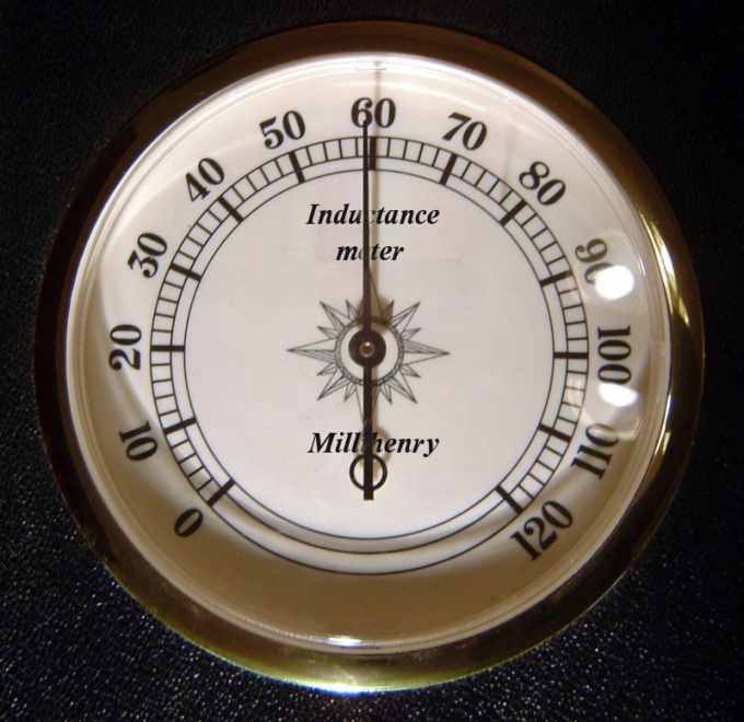
How to measure the inductance of a coil, choke.
Sorry for the quality of some of the pictures (which are rich).
Take care of yourself and your loved ones!
collapse
The phrase "coil of thread" is familiar to everyone, but I think not everyone has heard about the inductor. What do you mean by "coil"? Well ... it's probably some kind of bullshit, on which threads, fishing line, rope, whatever! The inductor is exactly the same, but instead of a thread, fishing line or something else, ordinary copper wire is wound there in insulation. The insulation can be from a colorless varnish, from wire insulation, and even from cloth. Here the chip is such, although the wires in the inductor are very tight to each other, they are still isolated from each other. If you wind the inductors yourself, in no case try to take an ordinary bare copper wire!
Any inductor, oddly enough, has an inductance :-) The inductance of the coil is measured in Henry (H), denoted by the letter L and measured with an LC meter. What is inductance? Let's figure it out. If an electric current is driven through the wires, then it will create a magnetic field around itself:
where B is the magnetic field, I is the current strength.
And let's take and wind this wire into a spiral and apply an electric current to its ends:
And we got this picture with magnetic field lines:
Roughly speaking, the more lines of the magnetic field cross the area of this solenoid, the area of the cylinder is obtained, the greater the magnetic flux (F). Since an electric current flows throughout this structure, it means that at this moment it has some kind of Current Strength (I). And the coefficient between magnetic flux and current strength is called inductance, and is calculated as follows:
From a scientific point of view, inductance is the ability to extract energy from a source electric current and store it in the form of a magnetic field. If the current in the coil increases, the magnetic field around the coil expands, and if the current decreases, the magnetic field contracts. The inductor also has very interesting properties. When an electric current is applied to the coil constant voltage, a voltage appears in the coil opposite to the voltage of the electric current and it then disappears after a few fractions of a second. This opposite voltage is called the Electromotive Force of self-induction, or simply - the EMF of self-induction. This emf depends on the inductance of the coil. Therefore, at the moment the voltage is applied to the coil, the current strength smoothly changes its value from 0 to a certain value within fractions of a second, because the voltage, at the moment the electric current is applied, also changes its value from zero to a steady value, according to Ohm's Law:
where I is the current in the coil, U is the voltage in the coil, R is the resistance of the coil.
As we can see from the formula, the voltage changes from zero to the voltage supplied to the coil, therefore the current will also change from zero to some value. The coil resistance is constant.
And the second joke in the inductor is that if we open the circuit of the inductor - the current source, then our self-induction EMF will be added to the voltage that we applied to the coil. Consequently, the current will be greater at the very beginning, and then quietly drop to zero. The decay time of the current also depends on the inductance of the coil.
Let's draw the first conclusions about the operation of the inductor when a direct current is applied to it. When an electric current is applied to the coil, the current strength will increase smoothly, and when the electric current is removed from the coil, the current strength will increase sharply in the coil and gradually decrease to zero. In short, the current in the coil cannot change instantly. This is known in electronics as the first law of commutation. Uff, well, that's it, the hardest part is over :-).
Inductors are divided mainly into two classes: with a magnetic and non-magnetic core. Below in the photo is a coil with a non-magnetic core.
But where is her heart? Air is a non-magnetic core :-). Such coils can also be wound on some kind of cylindrical paper tube. The non-magnetic core inductance is used when the inductance does not exceed 5 milliHenry.
And here are the core inductors:
Mostly use cores made of ferrite and iron plates. Cores increase the inductance of the coils at times. Ring-shaped cores (toroidal) allow you to get large inductance than just cores from a cylinder.
Ferrite cores are used for coils of medium inductance:
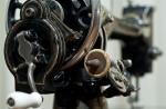
Coils with a large inductance are made like an iron core transformer, but there is one difference: they have only one primary winding:
On what factors does the inductance of a coil depend? Let's do some experiments. I wound a coil with a non-magnetic core. Its inductance is so small that the LC meter shows zero to me.
Has a ferrite core
I begin to insert the coil into the core to the very edge
Once upon a time, myths about the super efficiency of an antenna using mercury, a little later than tin beer cans, circulated among the "homemade" television antennas (though you can make a good antenna for Wi-Fi from a beer can, but not a television one). There are probably similar myths about cores, especially since the very names of modern magnetic materials (isoperm, permendur) inspire confidence in their exceptional efficiency. Consider the question of using a magnetic core in a linear signal circuit, how does it affect the parameters of the coil?
I will not delve into the theory and talk about diamagnets, paramagnets, ferromagnets, domains, about the hysteresis loop. This is a topic for a long serious discussion. I will try to describe it in an accessible way, on the fingers.
So, the magnetic core concentrates the magnetic field and increases the inductance with the same design parameters of the coil or allows you to reduce its dimensions with the same inductance. Let's try to choose a core for a speaker system filter - a crossover "and to save copper. The core must have permanent magnetic properties up to frequencies of at least 40,000 Hz at a fairly high currents magnetization. What choice do we have?
Modern magnetic materials are divided into three groups:
- Metal:
- Commercially pure iron (electrotechnical mild steel).
- Electrical silicon steels (transformer steel).
- Iron-nickel doped crystalline alloys - permalloy, superpermalloy, mumetal, isoperm, permendyur, perminvar, alfer, alphenol, etc.
- Amorphous and nanocrystalline materials - vitrovac, vitroperm
- Powder materials, magnetodielectrics - thin powders of carbonyl iron, permalloy or alsifer, mixed with some kind of dielectric binder.
- Ferrites are ceramic magnetic materials.
Electrical mild steel can only be used in DC circuits, such as relays, due to unacceptably large eddy currents in alternating current and big losses for remagnetization.
transformer steel a little better. To reduce eddy currents, the core is collected from separate plates. However, above 1000 Hz, such a core has unacceptable losses at high magnetizing currents.
Iron-nickel alloys they have a very high initial magnetic permeability, they can operate at frequencies up to 100 kHz, but at the same time they have a low saturation induction, i.e. they cannot work in strong fields. They have proven themselves as an indispensable material in the magnetic heads of tape recorders, sensors, magnetic screens.Amorphous and nanocrystalline materials appeared later than permalloys. They have a wider frequency range and slightly higher saturation induction than permalloy. They are used as current transformers in new electricity meters, pulse transformers in power supplies, compensated chokes and as more quality replacement permalloys.
Magnetodielectrics have a wide frequency range up to tens of megahertz, depending on the material, but low magnetic permeability and saturation induction. They can only work in weak fields. They are used in RF technology for the manufacture of magnetic circuits, cores of inductors, etc.
Ferrites have the lowest eddy current losses and, accordingly, can operate at the most high frequencies from all magnetic materials. However, they have a low saturation induction. Distinctive feature one of them is the strong dependence of parameters on temperature, as well as the aging of the material, the deterioration of its properties over time. The scope of each brand of ferrite is determined by the critical frequency, above which losses increase sharply and magnetic permeability decreases.
A general trend can be traced - with the improvement of the frequency parameters of the material, its saturation induction decreases, i.e. the ability to work in strong fields, as well as magnetic permeability.
The most important thing is that any magnetic material changes its properties depending on the frequency and strength of the magnetizing field. And this means that the core inductor becomes a non-linear element and introduces non-linear distortions into the signal passing through it, especially at high inductance and current strength. Ferrites are also affected by temperature.
Why are we making a crossover? 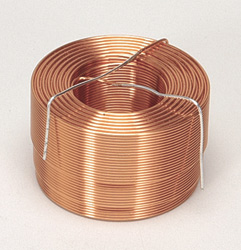 To divide the signal by frequency, each into its own head. This will reduce non-linear distortion, slightly increase power, improve the sound quality of the speaker. The inductance in such a filter is not small, and so is the current. Therefore, by introducing a core (any one!) into the coil, we will not only not achieve our goal, but we will also move away from it, introducing additional distortions into the signal. Therefore, you will have to give up saving on copper and make a coil as in the figure, without a core. True in the case of powerful acoustic systems we get monstrous, heavy and expensive coil. In this case, you have to compromise and use a core of high-quality ferromagnets. But it must be calculated so that it works far from the saturation mode, which means that its dimensions will also be impressive.
Cores in the form of steel tubes, rods made of "super iron" do not make sense at all, well, except in induction heating installations, where eddy currents in the core play a positive role. In circuits where the signal level is weak and the core is far from saturation, the decisive factor is the cutoff frequency of the core. With the same inductance, the core even increases the quality factor of the coil.
In RF chokes, core losses play a positive role by expanding its frequency range.
Conclusion: the selection of the core for the inductance in the signal linear circuit must be approached carefully, taking into account both the frequency range and maximum level signal, as well as the amount of permissible distortion.
This does not apply to pulse signals and circuits, everything is different there ...
Instruction
Wind additional turns to the coil. This will increase the inductance coils with unchanged parameters of its other structural elements, and the variometer ( coils with a moving core) - will shift both limits of inductance change (upper and lower) towards increase. When winding additional turns, it may turn out that they do not fit on the frame. Resist the temptation to use thinner wire than that originally used in the coil, so as not to cause the winding to be heated by the current flowing through it.
To the coil that does not have a core, add one. But remember that it must be made of a material in which the operating frequency coils no eddy current losses occur. For an electromagnet operating on DC, a solid steel core is suitable, for a 50-Hz transformer - a core recruited from oxidized steel sheets, in higher-frequency coils you will have to use cores made of ferrites of various grades.
Remember that even with the same number of turns and other things being equal, a larger diameter coil will have a larger inductance. It is clear, however, that more wires will be required for its manufacture.
Ferrite is available with different magnetic permeability. Replace one ferrite core in the coil with another that has a higher value for this parameter, and its inductance will increase. But at the same time, the cut-off frequency will decrease, at which such a coil can operate without noticeable losses in the core.
Exist coils equipped with special mechanisms for moving the core. To increase the inductance in this case, push the core inside the frame.
A closed magnetic circuit, ceteris paribus, provides more inductance than an open one. But try not to use such a solution in transformers and chokes operating in the presence of a constant component. It is able to bias and saturate a closed core, thereby, on the contrary, causing a decrease in inductance coils.
Ferrite cores are widely used in household and radio engineering. The main purpose of their use is to eliminate interference in control and power electrical conductors.
Ferrites are called chemical compounds iron oxide with oxides of other metals. The composition of the substance may vary depending on the required properties of the finished product.
Core production
Ferrite cores are produced using powder casting technology. A mixture of powders containing the necessary components in carefully adjusted proportions is pressed into a blank of the required shape, which is baked at a temperature of up to one and a half thousand degrees. Baking can be carried out both in an air environment and in a special gaseous atmosphere. At the last stage of manufacturing, the ferrite product slowly cools down over several hours. This technology not only makes it possible to produce alloys with desired characteristics, but also to produce products that do not require further processing.Ferrite Core Applications
Ferrite cores are most widely used in electrical and radio engineering. Since ferrite has a high magnetic transmission capacity and low electrical conductivity, it is indispensable for the assembly of low-power transformers, including pulse ones. Also, ferrite cores are used as a means of passive protection against high-frequency electrical interference. This phenomenon is most typical for switching networks of control devices, where interference can be induced even in a shielded cable, reducing the efficiency of signal transmission.Ferrite Core Types
For winding transformers, U-shaped and W-shaped ferrites are produced. The rod form of ferrite products is used in the manufacture of magnetic circuits: for example, cores for high inductance coils are made from ferrite. The common man most often meets ferrite rings and cylinders that are used as noise filters on communication cables: USB, HDMI, LAN and others. Advanced technology makes it possible to produce very complex products, sometimes less than a tenth of a millimeter in size.The advantage of ferrite over similar magnetic circuits
The low electrical conductivity of the material makes it possible to avoid the formation of eddy currents during magnetization reversal of the magnetic circuit. According to this indicator, ferrite surpasses even finely laminated electrical steel. Also, ferrite can be given certain properties at the production stage, which allows you to adapt the product in advance and with high accuracy to the needs of a specific device in which the ferrite will be used. Ferrite can actively absorb, dissipate or reflect interference induced in the cable, which is especially important in the construction of high-precision devices: low weight and dimensions ferrite cores make it possible to use them without disturbing the layout of equipment inside complex devices or complexes.An inductor is capable of storing magnetic energy when an electric current flows. Its main characteristic is its inductance, which is denoted by the letter L and is measured in Henry (H). Inductance coils depends on its characteristics.

You will need
- coil material and its geometrical parameters
Instruction
From this data, calculate the value of the inductance of the coil. To do this, divide the voltage value in series by 2, the number 3.14, the values of the frequency of the current and the strength of the current. The result will be the value of the inductance for this coil in Henry (H). Important note: connect the coil only to an alternating current source. Active resistance the conductor used in the coil should be negligible.
Then find inductance solenoid. To do this, raise the number of its turns to the second power, multiply the result by 3.14, the diameter to the second power and divide the result by 4. Divide the resulting number by the length of the solenoid and multiply by 0.0000012566 (1.2566 * 10-6). This will be the value of the inductance of the solenoid.
If possible, use a special device to determine the inductance of a given conductor. It is based on a circuit called an AC bridge.
The inductance of a coil can be measured directly or indirectly. In the first case, you will need a direct-reading or bridge device, and in the second you will have to use a generator, a voltmeter and a milliammeter, and then carry out a series of calculations.
You will need
- - direct-reading or bridge inductance meter;
- - sinusoidal voltage generator;
- - AC voltmeter and milliammeter;
- - frequency meter;
- - scientific calculator.
Instruction
To measure the inductance with a direct-reading device, connect a coil to it, and then, successively selecting the measurement limits with the switch, select one of them so that the result is approximately in the middle of the range. Read the result. If the meter has an analog scale, take into account the division value as well as the factor indicated next to the corresponding switch position when reading the result.
On the bridge instrument, after each range change, move the bridge balance control knob to any of the extreme provisions, and then rotate it all the way in the opposite direction. Find a range where you can balance the bridge with this knob. Having achieved the disappearance of sound in the speaker or headphones, or the decrease in the readings of the arrow indicator to zero, read the readings on the regulator scale (but do not pointer device). In this case, as in the previous case, take into account the division price and the coefficient by which the readings should be multiplied in this range.
To measure inductance indirectly, assemble a measuring circuit. An AC voltmeter, switched to the limit at which the upper limit of the range corresponds to a voltage of several volts, connect in parallel with the generator output. Connect the frequency meter there as well. Also, in parallel with them, connect a series circuit consisting of the inductor under test, as well as an AC milliammeter. Both devices must show the actual, not the amplitude values of the measured quantities, and also be designed for a sinusoidal waveform.
On the generator, turn on the sinusoidal voltage generation mode. Get the voltmeter to show about two volts. Increase the frequency until the milliammeter reading begins to decrease. Get them reduced to about half the original value. Select the limit on the frequency meter that corresponds to the measured frequency. Read the readings of all three instruments, and then turn off the generator and disassemble the measuring circuit.
Convert instrument readings to SI units. Divide the voltage by the current. It turns out inductive reactance coils at the frequency at which the measurement was made. It will be expressed in ohms.
Calculate the inductance using the formula: L=X/(2πF), where L is the frequency, G (henry), X is the inductive reactance, Ohm, F is the frequency, Hz. If necessary, convert the result of the calculation to derived units (for example, millihenry, microhenry).
note
Do not touch the elements of the measuring circuit when it is energized.
An inductor can store magnetic energy when an electric current flows. The main parameter of the coil is its inductance
You will need
- Inductor and its parameters
Instruction
The inductance of a short conductor is determined by the formula: L \u003d 2l (ln (4l / d) -1) * (10 ^ -3), where l is the length of the wire in centimeters, and d is the diameter of the wire in centimeters. If the wire is wound on a frame, then this design forms an inductor. The magnetic flux is concentrated, and the value of the inductance increases.
The inductance of the coil is proportional to the linear dimensions of the coil, the magnetic permeability of the core and the square of the number of winding turns. The inductance of a coil wound on a toroidal core is: L = ?0*?r*s*(N^2)/l. In this formula, ?0 is the magnetic constant, ?r is the relative magnetic permeability of the core material, which depends on the frequency, s is the cross-sectional area of the core, l is the length of the center line of the core, N is the number of turns of the coil.
The inductance of the inductor in µH can also be calculated using the formula: L = L0*(N^2)*D*(10^-3). Here N is the number of turns, D is the diameter of the coil in centimeters. The coefficient L0 depends on the ratio of the length of the coil to its diameter. For a single-layer coil, it is: L0 = 1/(0.1*((l/D)+0.45)).
If coils are connected in series in a circuit, then their total inductance is equal to the sum of the inductances of all coils: L = (L1+L2+...+Ln)
If the coils are connected in parallel, then their total inductance is: L = 1/((1/L1)+(1/L2)+...+(1/Ln)).
The formulas for calculating the inductance for various circuits for connecting inductors are similar to the formulas for calculating resistance with the same connection of resistors.
An inductor is capable of storing magnetic energy when an electric current flows. The main parameter of the coil is its inductance. Inductance is measured in Henry (H) and is denoted by the letter L.