The barometer circuit for measuring atmospheric pressure is built using the MPXHG6115 pressure sensor. The sensor itself provides a voltage proportional to the air pressure at its output. The operating range covers atmospheric pressure (90 - 110 kPa) at sea level. The minimum operating air pressure of the sensor is 15 kPa, which allows it to be used even in mountainous areas. To do this, however, you need to recalculate the resistors on its board. For atmospheric pressure in an area near sea level, the output voltage range of the sensor is 3.625 - 4.55 volts. In the analog part of the circuit (shaded in the diagram), the output is a linear voltage in the range of 0 - 5 V, which is in the normal range of the microcontroller ADC. The mapping is performed using two DTs. The left one (in the diagram) provides the optimal load resistance for the sensor (51 kOhm) and inverts the reference voltage of about 2.5 V. The reference voltage is obtained using a voltage divider consisting of two 11.5 kΩ resistors (1% accuracy). The right op amp provides the necessary voltage scaling and initial setting to 0. We recommend using a dual OPA2374.


Specifications
- Measuring range: 700 - 800 mmHg
- Supply voltage: 5 volts
- Current consumption: 40 mA
The zoom sensor and analog amplifier are assembled on a small printed circuit board. It connects to the main board with 3 wires. The test circuit consists of a microcontroller and an LCD module with an interface mounted on its rear side. The interface card establishes all communications with the PIC using only two wires and its software implements a simplified version of the standard I2C interface. The PIC16F84 controller program assigns its pin-RC3 input to the ADC input. It simply calculates the pressure depending on the input voltage according to the formula, converts it to BCD and displays it on the screen.
Description of the clock.
There was a need to update the alarm clock in the bedroom. For the alteration, a Chinese watch VST-716 was used. Of the shortcomings inherent in them: flickering of the indicator; the color of the indicator in my model was an annoying red; for the night, the brightness of the indicator is too bright, for the day it is insufficient; and most importantly, although battery operation is provided, but this is only the work of the clock so that it does not go astray, the indicator and the alarm clock do not work. Oh, and also boring.
At the opening, I found out that the dynamic indication goes with the network frequency (hence the flicker). The indicator is "truncated", that is, there are no LEDs in unused segments. Switching for dynamics is, to put it mildly, strange and is incorporated by the design of the indicator. I came to the conclusion that in addition to the body and buttons (after rework), nothing will work. Therefore, I decided to radically redo everything.
1. Functions.
1.1. Hours, 24-hour time display format, hours:minutes.
1.2. Digital Accuracy Correction. Daily correction ±25 sec. is possible. The set value of 1 hour 0 minutes 30 seconds will be added/subtracted from the current time.
1.3. Alarm. At the set time (setting point 2.2.1), short double signals are heard for one minute. You can turn off the sound ahead of time by pressing the button ALARM. When the alarm is enabled (the switch on the back of the clock is in the On), when the time is displayed, a dot is displayed in the least significant digit. If the indicator has been turned off, then when the alarm goes off, automatic brightness control is turned on.
1.4. Thermometer. The range of the measured temperature is -55.0 ÷ 125.0 ° C. If the temperature is above +99.9 or below -9.9 ° C, tenths of a degree are not displayed. In case of an error in the operation of the sensor, dashes are displayed on the indicator.
1.5. Barometer. Measurement of atmospheric pressure in mm Hg. Art.
1.6. Indication. Alternately, the change of indication is animated. The indication time is set in the settings section 2.2.3. Push button MINUS manual selection of output information. Clicking on a button SET puts the watch in the automatic change of information mode.
1.7. Using the non-volatile memory of the microcontroller to save settings when the power is turned off.
1.8. Manual or automatic adjustment of the brightness of the indicator depending on the illumination.
The choice of the brightness mode is made in the main mode with the button PLUS in a circle: the indicator is off - automatic brightness control - manual brightness control mode.
The limits of brightness adjustment in automatic mode and the brightness level in manual mode are set in the settings of section 2.2.4.
1.9. Work from the independent power supply (two batteries "AAA").
2. Setting.
2.1. When the power is turned on, the clock is in the main mode.
2.2. Push button MENU you enter the settings mode and select a group of parameters to set. Within the group, the selection of the parameter to be set is made by the button SET. In turn, available for installation:
2.2.1. Group ALAr:
Minutes of the alarm;
Alarm hours.
2.2.2. Group CLOC:
Seconds (reset to zero when pressing the buttons PLUS or MINUS);
Correction amount. In the most significant digit, the symbol " With".
2.2.3. Group diSP:
Time of indication of the current time. In high-order digits, the symbols " tc". Setting range 0÷99 sec. If set to 0, the time will not be displayed;
Temperature indication time. In high-order digits, the symbols " tt". Setting range 0÷99 sec. If set to 0, the temperature will not be displayed;
Pressure indication time. In high-order digits, the symbols " tP". Setting range 0÷99 sec. If set to 0, pressure will not be displayed;
Animation speed selection. In the most significant digit, the symbol " P". The setting range is 0÷99. One unit corresponds to about 2 ms, the higher the value, the slower the animation.
2.2.4. Group LiGH:
Minimum brightness threshold for automatic mode. In high-order digits, the symbols " L_".
The maximum brightness threshold for automatic mode. In high-order digits, the symbols " L¯".
Brightness level in manual mode. In high-order digits, the symbols " L-".
2.3. The parameter to be set flashes.
2.4. Holding buttons PLUS/MINUS the parameter is quickly set.
2.5. After ~10 seconds from the last pressing of the buttons, the watch will switch to the main mode of operation, and the new parameters will be written to the non-volatile memory.
3. Work from an independent power source.
3.1 In the absence of the main power, the clock continues to work if batteries are installed.
3.2 When powered by batteries, the indication turns off, the alarm clock remains in operation.
3.3 When the alarm goes off within a minute, double beeps are heard, the indicator with the time display flashes. Mute the sound by pressing the button ALARM or switch on the back of the clock to position Off.
3.4 Briefly (~4 sec) you can turn on the indication by pressing the button ALARM. In this mode, viewing and setting parameters are available.
3.5 When operating on batteries, temperature and pressure measurements are not performed.
3.6 The brightness of the indicator is set to manual mode.
4. Notes.
1. For the minimum and maximum brightness thresholds, the setting range is 0 ÷ 99, but the program introduces restrictions: the minimum cannot be greater than or equal to the maximum and vice versa.
2. When setting the brightness parameters, the information on the indicator is displayed with the selected brightness value, except when the clock is running on batteries.
3. It is necessary to measure the speed of animation and the time of displaying information. If a slow animation and a short display time are selected, then it may turn out that the information does not have time to fully update before the next shift.
5. Features of the scheme.
1. If you intend to use the automatic brightness control function of the indicator, then a photoresistor is installed instead of RV1. And the value of the resistor R17 should be selected to obtain the desired system sensitivity.
2. The temperature sensor can also work on a 2-wire connection scheme. If you plan to measure the temperature in the room where the clock is installed, then the sensor should still be taken out of the clock case.
3. The BUZ1 tweeter must have a built-in generator. Depending on the current consumption, it may be necessary to install an amplifier (transistor switch).
4. Indicator - 4 single-digit 0.8" SM610806B/8, common anode, blue. Brightness is more than enough.
5. When flashing the MK, you should install FUSE to work from the internal clock generator with a frequency of 8 MHz. An example of installing FUSE for the CVAVR program is in the screenshot.

6. Pressure sensor GY-65.

7. The project (this is essentially a circuit already) does not show the power supply pins of the microcircuits.
8. The clock is powered by an external source of stabilized voltage + 5V, the current consumption is about 30 mA. In my case, a mobile phone charger is used. Backup power - two elements "AAA".

The archive contains a set of files: firmware, a project in Proteus for simulation, two Proteus files, which were used to build seals, a description, a photo of the appearance. I don’t post printed circuit boards in the article, because during the development I made a number of mistakes and I had to make some changes already on the board. In addition, the board is made specifically for this case. If anyone needs it - write, I'll post it in the form. On occasion, I will take a picture of the internal structure of the clock.
For discussion created in the forum.
Temperature
and ambient air pressure have a big impact on well-being
person. It is important to know them both on a hike, and in the country, and at home. Proposed compact
The device is perfect for this. It can also be used for
a rough estimate of the height, for example, when climbing mountains. Decrease
pressure per 1 mmHg corresponds to an increase in height above the level
sea for about 10 m.
limits
measurement and instrument error
are determined mainly by the sensors used in it temperature -55 ... +125
°C, atmospheric pressure 225. 825 mmHg The instrument is powered by
voltage 9 V from a galvanic battery of the “Krona” type or a network
adapter Current consumption - 30 mA (with the LCD backlight off). Dimensions
cases - 118 × 72 28 mm. The operation of the device was tested at temperatures from -5 to
+25 С Pressure measurement error did not exceed 4 mm Hg Diagram
device is shown in Fig. 1 and the module assembled on a separate board
pressure measurement is highlighted by a dash-dotted line.
Required
for the operation of the sensor, clock pulses with a frequency of 32768 Hz are generated by a quartz
generator on the elements of the chip DD1 In principle, these pulses could
form the DD2 microcontroller using one of the timers available in it
But this would require the complexity of the program.
Voltage
3.6 V to power the B1 sensor and the DD1 microcircuit was obtained using the VD1 zener diode
Resistors R1 -R3 - load for the lines connecting the sensor with the microcontroller
1C interface and XCLR signal The printed circuit board of the pressure measurement module is shown
in fig. 2
Although
the HP03SB sensor also contains a built-in temperature meter, its readings
used by the DD2 microcontroller program only to refine the results
pressure measurements. The HG1 LCD displays along with the pressure value
readings of another temperature sensor - DS1624 (B2) The reason for this is simple - it
more precisely If necessary, sensor B2 can be made remote and placed where
temperature is of most interest. When installed in the instrument housing
this sensor should be placed on the side wall, making a window in it along its
dimensions Otherwise, an error of 1.5 ..1.8 'C is inevitable, as I have seen in practice
The supply voltage +5 V is stabilized by the DA1 microcircuit
resistor R8 set the best image contrast on the LCD.
SB1 turn on the backlight of his scoreboard. The remaining elements are necessary for work
microcontroller Elements R7 R9 SU VD2 - circuit for installing the microcontroller in
initial state Quartz resonator ZQ2 with capacitors C11.C12 - frequency setting
microcontroller clock generator circuit.
On
rice. 3 shows a drawing of the main printed circuit board of the device and in fig. 4 -
location of parts on it In the via shown filled (board
in fig. 2), it is necessary to insert and solder on both sides of the wire
jumper. A panel must be provided for the DD1 microcontroller, since
in the process of setting up the device, this microcircuit will have to be removed and again
install.
Let's stop
on some features of the HP03SB sensor. general view and overall dimensions
shown in fig. 5 To determine the pressure, you must first read
from the memory of the instance of this sensor installed in the device two-byte
values of coefficients С,-С- and one-byte values of parameters A-D. All of them are individual
for this instance.
results
measurements are two double-byte numbers - D1 - pressure D2 -
temperature. Reading them from memory
sensor, the program must calculate the auxiliary values
More
For details on the HP03SB sensor, see . However, it should be noted
that there are incorrect addresses of the sensor's internal memory, which store
its individual constants. Please use the addresses provided.
c Other sensors of the NRZ series can be used in the device. Some of them
have less accuracy, others differ in design.
Job
the program starts with the initialization of the ports of the microcontroller and the LCD. Successful
initialization is confirmed by the display on the display of the inscription “TER-MOBAR” (letter
N omitted). Then the pressure sensor is initialized, read the state of the register
the status of the TW1 module of the microcontroller is not checked.
For
reading the coefficients and parameters of the sensor is a special program
ReadCC, which must be loaded into the program memory of the fully assembled microcontroller
device (with connected pressure measurement module), turn it on and through
turn off for a few seconds. After that, you need to remove the microcontroller and with
using the programmer to read the contents of its EEPROM. In it, at the addresses
indicated in the table. 1, the values of individual coefficients and parameters are found
sensor. Next, you need to open the file of the working program of the barometer-thermometer
BARO-2 asm, find in it the fragment given in Table. 2, and fix the values
constants declared there according to those read from EEPROM Parameter D
not used in the program
Now
the program is ready to work with the sensor instance installed in the device
It remains to broadcast it using AVR Studio and load the resulting HEX file
into the microcontroller. Please note that a similar file attached to the article is calculated
to work with the sensor that the author had. If you load it into the microcontroller
a device with a different copy of the pressure sensor will work but give inaccurate
testimony
IN
development used fragments of programs from and . Conversion Routines
numbers from hexadecimal to binary decimal have been redesigned with
taking into account the digit capacity of numbers. Subroutines for multiplying and dividing double-byte
numbers intended for microcontrollers of the MCS-51 family are translated into
assembly language AVRASM Least modified subroutine
LCD control, only the features of the MT-10S1 indicator are taken into account, and for input and output
signals used other ports of the microcontroller.
Today I would like to consider a device that is a barometer - a measure of atmospheric pressure. The use of such a device is necessary to monitor the current atmospheric pressure expressed on the indicator of the device in two units of measurement - in the international system of Pascal units (Pa or Pa) and in non-systemic units - millimeters of mercury. The latter is most likely more familiar to our countries, as it is used in weather forecasts. However, the functionality of this device is not limited to measuring only atmospheric pressure; temperature measurement and determination of altitude above sea level (altitude) are also implemented.
The device diagram on the ATmega8 AVR microcontroller is shown below:
The BMP180 manufactured by Bosch was used as an atmospheric pressure sensor in the circuit. In truth, this company does good and high-quality things, but the datasheet for this sensor is not very detailed in comparison with the datasheets of other companies, it will be difficult to figure it out without the experience of reading such documentation. Bosch engineers considered it necessary to provide information only on the most basic parameters, but everything we need is there, albeit briefly in places. The BMP180 atmospheric pressure sensor can operate both via the I2C interface and via the SPI interface (selected by connecting the necessary sensor outputs). This circuit uses an I2C interface. Since the sensor requires a power supply of up to 3.3 volts, and the microcontroller is powered by 5 volts DC, I2C level matching must be applied for correct operation. For this purpose, a microcircuit manufactured by NXP PCA9517 was chosen. The sensor itself takes power from a voltage regulator of 3.3 volts, the same power is supplied to the pull-up resistors R6 and R7. The signal levels are converted by the PCA9517 microcircuit and the signals from the atmospheric pressure sensor are transmitted to the microcontroller with levels up to 5 volts. 5 volts is connected to the pull-up resistors R4 and R5. These pull-up resistors (pull-up) are necessary for the operation of the I2C protocol - with their help, high signal levels are formed, and when the microcircuit fails this voltage from the pull-up resistors to zero potential, a logic low signal is formed. In this configuration, the voltages of logical levels of 3.3 and 5 volts can be dispensed with as a last resort and without matching the levels, since according to the standards for such supply voltages, the potentials of the low levels are the same, and the high level is the same for both 5 volts and 3 .3 volts, the difference is only in the maximum values. However, it was decided not to take risks and still apply the harmonization of levels - to do everything according to the rules. Pull-up resistors can be taken from 4.7 kΩ to 10 kΩ. Capacitors C3 and C4 are necessary for stable operation of the atmospheric pressure sensor.
An important function in this atmospheric pressure sensor is the calibration of the obtained measurements. There are 11 coefficients in the sensor's memory to improve the measurement accuracy of the parameters. However, not everything is so simple - it is not so easy to multiply by these coefficients. to get the final results in the datasheet there is a whole calculation example on page 15, the documentation for the sensor is below. In accordance with this information, we compose a program for the microcontroller in the C language.
// get temperature and atmospheric pressure values taking into account calibration coefficients void BMP180_calculation (int32_t* temperature, int32_t* pressure) ( //int8_t i; int32_t ut=0; int32_t up=0; int32_t x1, x2, b5, b6, x3, b3, p; uint32_t b4, b7; BMP180_get_temper(); ut+=temperature_1; BMP180_get_pressure(); up=pressure_1; x1 = ((int32_t)ut - (int32_t)ac6) * (int32_t)ac5 >> 15; x2 = ( (int32_t)mc<< 11) / (x1 + md); b5 = x1 + x2; *temperature = (b5 + 8) >> 4; b6 = b5 - 4000; x1 = (b2 * ((b6 * b6) >> 12)) >> 11; x2 = (ac2 * b6) >> 11; x3 = x1 + x2; b3 = (((((int32_t) ac1) * 4 + x3)<>2; x1 = (ac3 * b6) >> 13; x2 = (b1 * ((b6 * b6) >> 12)) >> 16; x3 = ((x1 + x2) + 2) >> 2; b4 = (ac4 * (uint32_t) (x3 + 32768)) >> 15; b7 = ((uint32_t) (up - b3) * (50000 >> OSS)); //p = b7< 0x80000000 ? (b7 * 2) / b4: (b7 / b4) * 2; if (b7 < 0x80000000) { p = (b7 << 1) / b4; } else { p = (b7 / b4) << 1; } x1 = (p >> 8) * (p >> 8); x1 = (x1 * 3038) >> 16; x2 = (-7357 * p) >> 16; *pressure = p + ((x1 + x2 + 3791) >> 4); )
Each sensor has its own calibration coefficients (apparently they are completely set at the factory in accordance with some kind of control tests). These coefficients must be read from the sensor's storage register before use.
// get calibration data void BMP180_Calibration (void) ( ac1 = Read(0xAA); ac2 = Read(0xAC); ac3 = Read(0xAE); ac4 = Read(0xB0); ac5 = Read(0xB2); ac6 = Read (0xB4); b1 = Read(0xB6); b2 = Read(0xB8); mb = Read(0xBA); mc = Read(0xBC); md = Read(0xBE); ) // read 16 bit register uint16_t Read(uint8_t address) ( uint16_t msb=0; uint16_t lsb=0; uint16_t data; i2c_start_cond(); // start i2c i2c_send_byte(BMP180_W); // send device address, write mode i2c_send_byte(address); // send memory address i2c_stop_cond() ; // stop i2c i2c_start_cond(); // start i2c i2c_send_byte(BMP180_R); // send device address, read mode msb = i2c_get_byte(0); lsb = i2c_get_byte(1); i2c_stop_cond(); // stop i2c data = (msb<< 8) + lsb; return data; }
To get the value of the altitude or height above sea level, we also use the formula given in the datasheet and get the following function:
// function for calculating the height above sea level (altitude) (the function takes a lot of memory due to mathematical functions!!!) void bmp180CalcAltitude(int32_t pressure)( float temp; temp = (float) pressure/101325; temp = 1-pow (temp, 0.19029); //altitude = round(44330*temp*10); altitude = 44330*temp*100; //get altitude in dm )
Depending on the need, this function can be thrown out of the source code, since you need to use the library for the calculation - the methods for calculating the necessary actions implemented in it take a lot of memory, both flash and operational, but I haven’t come up with anything better yet.
Also, this sensor can measure atmospheric pressure with different accuracy. To set the accuracy, it is necessary to transfer this value to the sensor via I2C and correctly set the delay before reading the registers with the received data (depending on the accuracy, the sensor needs more or less time to measure). the program code looks like this:
// read atmospheric pressure void BMP180_get_pressure(void)( i2c_start_cond(); // start i2c i2c_send_byte(BMP180_W); // send device address, write mode i2c_send_byte(0xF4); // send memory address i2c_send_byte(0x34+(OSS<<6)); // передача разрешения (oss) адреса памяти температуры i2c_stop_cond(); // остановка i2c _delay_ms(26); // время на замер (от 5 до 26 мс в зависимости от разрешения (oss)) i2c_start_cond(); // запуск i2c i2c_send_byte(BMP180_W); // передача адреса устройства, режим записи i2c_send_byte(0xF6); // передача адреса памяти i2c_stop_cond(); // остановка i2c i2c_start_cond(); // запуск i2c i2c_send_byte(BMP180_R); // передача адреса устройства, режим чтения D1=i2c_get_byte(0); // MSB D2=i2c_get_byte(0); // LSB D3=i2c_get_byte(1); // XLSB i2c_stop_cond(); // остановка i2c pressure_1 = ((D1 << 16) + (D2 << 8) + D3) >> (8-OSS); // calculate pressure (in Pa) )
When assembling the circuit, the BMP180 atmospheric pressure sensor was used on a Chinese-made factory printed circuit board (the module includes a 3.3 volt power regulator with capacitors, pull-up resistors for the I2C interface and capacitors in the power supply piping of the sensor itself, a microcircuit or simply a level matching circuit not on this board, so it must be used in another version):


The entire circuit is powered by a simple power supply module on a power transformer. The alternating voltage is rectified by four diodes VD1 - VD4 brand 1N4007, ripples are smoothed out by capacitors C1 and C2. The value of the capacitor C2 can be increased to 1000 - 4700 uF. Four rectifier diodes can be replaced by one diode bridge. Transformer applied brand BV EI 382 1189 - converts 220 volts AC to 9 volts AC. The power of the transformer is 4.5 W, which is quite enough and more with a margin. Such a transformer can be replaced by any other power transformer suitable for you. Either this power supply module of the circuit can be replaced with a switching voltage source, you can assemble a flyback converter circuit, or use a ready-made power supply from a telephone, for example - it's all a matter of tastes and needs. The rectified voltage from the transformer is stabilized on the linear stabilizer chip L7805,it can be replaced with a domestic analogue of the five-volt linear stabilizer KR142EN5A, or you can use a different voltage regulator chip in accordance with its connection in the circuit (for example, LM317 or switching regulators LM2576, LM2596, MC34063 and so on). Further, 5 volts are stabilized by another microcircuit - AMS1117 in performance, which gives 3.3 volts at the output. This voltage is used to power the BMP180 atmospheric pressure sensor in accordance with the documentation. The ratings of capacitors in the strapping of microcircuits of voltage stabilizers can vary over a wide range in the region of the taken order.
Well, the heart of the circuit is the Atmega8 microcontroller. This microcontroller can be used both in the DIP-28 package and in the SMD version in the TQFP-32 package. Resistor R3 necessary to prevent spontaneous restart of the microcontroller in the event of random noise on the PC6 pin. Resistor R3 pulls the positive supply to this pin, reliably creating a potential on it. To indicate the measured parameters, a liquid crystal (LCD or LCD) display SC1602 is used. It has 2 character strings with sixteen characters each. The LCD display is connected to the microcontroller using a four-bit system. Variable resistor R2 is needed to adjust the contrast of the characters on the display. By rotating the engine of this resistor, we achieve the clearest readings for us on the screen. The backlight of the LCD display is organized through the output "A" and "K" on the display board. The backlight is turned on through a current limiting resistor - R1. The higher the value, the more dimly the display will be illuminated. However, this resistor should not be neglected in order to avoid damage to the backlight. The power of all constant resistance resistors is 0.25 watts.
The circuit was assembled and debugged on a breadboard for Atmega8 microcontrollers:


As a result, this scheme has the following functionality:
- measurement and display of atmospheric pressure in two units of measurement (Pascals and millimeters of mercury column)
- measurement and display of ambient temperature
- calculation and display of the position of the sensor relative to sea level (altitude calculation)
- display data is updated every two seconds
In this device, the indication of the position relative to sea level is calculated, not measured. The calculation is carried out according to the recommended formula from the datasheet for the simplified calculation of the position relative to sea level depending on atmospheric pressure. As you know, the higher we are, the lower the pressure of the atmosphere. It is this dependence that is used in the calculation. However, due to the fact that for any particular territory the weather can change, and with it the atmospheric pressure will fluctuate. Based on these reflections, as well as experimental observations, the position above sea level will constantly float depending on fluctuations in atmospheric pressure (in theory, the height should not change at such a speed). This function is considered as additional and not entirely reliable (the level above the sea during the day can float plus or minus 5 percent - and this is a lot, I think). But it is the atmospheric pressure that is measured by this sensor quite accurately - the coincidence with the current weather forecast is from complete to a discrepancy of no more than one percent. The temperature in this sensor is also measured very accurately.
As a conclusion, I can say that this atmospheric pressure sensor performs its main functions very well and can be suitable for a home weather station, which we will deal with in the near future.
To program the Atmega8 microcontroller, you need to know the configuration of the fuse bits (the screenshot was taken in the AVR Studio program):

Attached to the article firmware for the microcontroller, the full source code for this device for working with the BMP180 sensor in the documentation for the sensor, as well as a short video demonstrating the operation of the circuit (we watch how the parameters change if you hold the atmospheric pressure sensor with your finger).
List of radio elements
| Designation | Type | Denomination | Quantity | Note | Shop | My notepad |
|---|---|---|---|---|---|---|
| IC1 | MK AVR 8-bit | ATmega8 | 1 | To notepad | ||
| IC2 | I2C interface IC | PCA9517 | 1 | To notepad | ||
| IC3 | Atmospheric pressure sensor | BMP180 | 1 | To notepad | ||
| VR1 | Linear Regulator | L7805AB | 1 | To notepad | ||
| VR2 | Linear Regulator | AMS1117-3.3 | 1 | To notepad | ||
| VD1-VD4 | rectifier diode | 1N4007 | 4 | To notepad | ||
| HG1 | LCD display | SC1602 | 1 | Based on HD44780 |
David W Bray
A description is given of the design of version 2.0 of an electronic barometer with a 1-Wire interface, which differs from the popular version 1.1a in twice the measurement accuracy.
As in version 1.1a, this design uses the MPX4115 integral pressure sensor from Motorola. Analog-to-digital conversion is performed by a DS2438 chip with a 1-Wire interface. In addition to these circuits, one operational amplifier, two voltage regulators, two diodes, an LED and several resistors and capacitors are used. Note that the original purpose of the DS2438 chip is a battery charge monitor.
The development history of version 2.0 can be found at http://davidbray.org/onewire/barometer.html .
Printed circuit board
As with the previous version 1.1a, the single-sided PCB for the version 2.0 barometer was designed by Jim Jennings. The printed circuit board for version 2.0 is more versatile; it can also be used to assemble a barometer circuit of version 1.1a.

Some subtleties
This circuit requires another additional power supply, which was not available in version 1.1a, since the MPX4115 pressure sensor requires about 7 mA of current, which is more than what can be taken from the 1-Wire interface line.
The scheme provides a resolution (pressure measurement accuracy) of about 0.00417 inHg (0.1059 mmHg or 0.0139 kPa) in the atmospheric pressure measurement range from 31.0 to 28.0 inHg (787.4 to 711.2 mmHg or 105.0 to 95.0 kPa). Even greater measurement accuracy can be achieved by reducing the range of measured atmospheric pressure values.
circuit diagram

This diagram does not show a connector. The complete scheme is given.
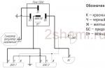
Circuit diagram description
The MPX4115 Pressure Transmitter provides a voltage range of 4.25 to 3.79 V when measuring pressure at sea level and approximately 2.77 V to 2.45 V at 10,000 feet (3048 m). This exceeds the input voltage range of the LM358N operational amplifier when powered from a 5 V source. The fact is that the output signal of the pressure sensor is measured, in fact, relative to its power rail, and not relative to ground, as it would be much more convenient.
Fortunately, the DS2438's ADC can handle signals up to 10V, so when powered by a 10V op amp, the MPX4115's signals will match well with the DS2438's input range.
The signal from the output of the pressure sensor MPX4115 through the RC filter is fed to the input of the operational amplifier U1B with a gain of about 4. An adjustable voltage is applied to the second input of the amplifier, which, summed with the output voltage of the pressure sensor, provides a level shift to match the ADC input.
Gain and offset are controlled by 10-turn trimmers. R3 sets the gain of U1A and R4 controls the offset.
Please note that the output of the pressure sensor is connected to the resistor R1 through a removable jumper. This is done so that the MPX4115 signal can be calibrated against an external voltage source.
Continue reading