| Name | Meaning |
| Working environment | non-aggressive gases (natural gas, compressed air) |
| Temperature environment, °С | -40 to +60 |
| Working environment temperature, °С | -30 to +60 |
| Inlet pressure range, MPa | 0,03–1,2 |
| Outlet pressure regulation limits, MPa | |
| RDG-P50N | 0,0015–0,04 |
| RDG-P50V | 0,04–0,6 |
| Throughput, m3/h | |
| at Pvx = 0.1 MPa | 1150 |
| at Рin = 1.2 MPa | 7700 |
| Excess outlet pressure at zero consumption (dead end), %, no more |
10 |
| Proportional band, % of Р out | 5 |
| Valve seat diameter, mm | 38 |
| Accession | flange according to GOST 12817-80 |
| Conditional passage Du | 50 |
| Service life, years | 20 |
Throughput of regulators
| R in, MPa | RDG-P50N | RDG-P50V | |||||||
| P out, MPa | |||||||||
| 0,0015 | 0,005 | 0,01 | 0,04 | 0,04 | 0,06 | 0,10 | 0,30 | 0,60 | |
| 0,03 | 650 | 650 | |||||||
| 0,05 | 850 | 850 | |||||||
| 0,1 | 1150 | 1150 | 1150 | 1150 | 1150 | 950 | |||
| 0,2 | 1750 | 1750 | 1750 | 1750 | 1750 | 1750 | 1700 | ||
| 0,3 | 2350 | 2350 | 2350 | 2350 | 2350 | 2350 | 2350 | ||
| 0,4 | 2950 | 2950 | 2950 | 2950 | 2950 | 2950 | 2950 | 2400 | |
| 0,5 | 3500 | 3500 | 3500 | 3500 | 3500 | 3500 | 3500 | 00 | |
| 0,6 | 4100 | 4100 | 4100 | 4100 | 4100 | 4100 | 4100 | 4100 | |
| 0,9 | 5900 | 5900 | 5900 | 5900 | 5900 | 5900 | 5900 | 5900 | 5500 |
| 1,2 | 7700 | 7700 | 7700 | 7700 | 7700 | 7700 | 7700 | 7700 | 7700 |
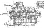
Device and principle of operation
The regulator consists of two functional blocks, an actuator and a control regulator (hereinafter referred to as the pilot).
The pilot consists of four functional blocks: a filter, a stabilizer, a booster and the pilot itself, mounted on one body.
The filter is mounted on the pilot body and provides fine cleaning working environment through a filter pad 14. Designed to ensure long-term uninterrupted operation of the pilot. The stabilizer is mounted on the body and provides a reduction in the inlet pressure coming through the inlet pipeline to the value necessary for the stable operation of the pilot and servo.
The stabilizer consists of a valve 15 with a seat, a membrane assembly 16 and a spring 17.
The forcing device is mounted on the housing and serves to increase the speed of the regulator's actuator. It consists of a spacer 19, a membrane assembly 20, a spring 21, a valve 22 and a throttle 23.
The pilot is directly mounted on the body and serves to control the main actuator of the regulator. The control is carried out by creating a control pressure by the pilot, which enters through the connecting pipeline into the control cavity of the actuator P2. The pilot consists of a valve 10, a membrane assembly 11, an adjusting spring 12, a plate 13 and an adjusting screw 18.
The design of the regulator includes fittings Ш1 and Ш2, through which the output pressure signal enters the actuator and the pilot.
Products RDG-P50N, RDG-P50V differ in the design of the membrane unit of the pilot 11 and a set of tuning springs.
The principle of operation of the regulator
The inlet pressure, having passed through the inlet flange 1, gate 6, is throttled between the sealing edge of the gate and valve 9, enters the outlet flange 8 and further through the pipeline. The gap between the plug and the valve is adjusted automatically by the pilot.
The principle of the pilot.
Gas with inlet pressure passes through the impulse pipeline through filter 14, is throttled to the required value, passing through the gap between valve 15 and the stabilizer seat. The gap between the valve and the stabilizer seat is provided automatically. After passing through the valve 15, the pressure enters the sub-membrane cavity of the stabilizer and acts on the membrane assembly 16, on the other hand, the output pressure of the main servo drive and the spring 17 act on the membrane assembly. As a result of this interaction, a force arises that is transmitted through the stem to the stabilizer valve, and it, in turn, moves either towards increasing the gap, or towards decreasing it. This ensures that the inlet pressure is reduced in the first stage.
1 - inlet flange; 2 - bushings; 3 - bellows assembly; 4 - return spring; 5 - membrane regulator assembly; 6 - shutter; 7 - limiting ring; 8 - outlet flange; 9 - valve; 10 - pilot valve; 11 - membrane pilot assembly; 12 - adjusting spring; 13 - adjusting plate; 14 - filter pad; 15 - stabilizer valve; 17 - stabilizer spring; 18 - adjusting screw; 19 - spacer; 20 - membrane forcing device assembly; 21 - spring forcing device; 21 - spring forcing device; 22 - valve; 23 - throttle.
Gas pressure regulator RDUK designed to reduce gas pressure and automatically maintain the outlet pressure within the specified limits, regardless of changes in the inlet pressure and gas flow. The regulator is applied in systems of gas supply of industrial, agricultural and household objects.
DN 50 are manufactured with a 35 mm seat, DN 100 with a 50, 70 mm seat, DN 200 with a 105, 140 mm seat. The diameter of the seat affects the capacity of the regulator, the larger the seat, the greater the capacity of the regulator.
On the basis of RDUK gas pressure regulators, we manufacture gas control points and gas control units of cabinet, block type or on a frame.
Produced RDUK models
RDUK is manufactured in the following modifications:
RDUK-50N(V) Du-50 with low or high outlet pressure and seat diameter 35 mm - RDUK-50N(V)/35;
RDUK-100N(V) Du-100 with low or high outlet pressure and seat diameter 50, 70 mm - RDUK-100N(V)/50(70);
RDUK-200N(V) Du-200 with low or high outlet pressure and seat diameter 105, 140 mm - RDUK-200N(V)/105(140).
RDUK-200 gas pressure regulators are available in four versions:
With low outlet pressure and seat diameter 105 mm - RDUK 200 MN/105;
- with low outlet pressure and seat diameter 140 mm - RDUK 200 MN/140;
- with high outlet pressure and seat diameter 105 mm - RDUK 200 MV/105;
- with high outlet pressure and seat diameter 140 mm - RDUK 200 MV/140.
Throughput of RDUK:
- RDUK 50 6500 m3/h
- RDUK 100 12000/24500 m3/h
- RDUK 200 47000/70000 m3/h
Climatic version corresponds to UZ GOST 15150 (from -45o C to +40o C).
The gas pressure regulator RDUK 200 complies with the requirements of GOST 11881, GOST 12820 and a set of documentation according to specification RDUK 200M.00.00.00.
Technical and performance characteristics regulators RDUK-50/100/200
|
Parameter or dimension name |
Values for type or variant |
|||||
|
RDUK-2N-50 |
RDUK-2N-100 |
RDUK-2N-200 |
||||
|
RDUK-2V-50 |
RDUK-2V-100 |
RDUK-2V-200 |
||||
|
Nominal diameter of the inlet flange, DN | ||||||
|
Seat diameter, mm | ||||||
|
Maximum inlet pressure, MPa (kgf/cm2) |
1,2 (12) |
1,2 (12) |
1,2 (12) |
0,6 (6) |
||
|
Outlet pressure setting range, MPa (kgf/cm2) |
for regulator low pressure |
0,005-0,06 (0,05-0,6) |
||||
|
for high pressure regulator |
0,06-0,6 (0,6-6,0) |
|||||
|
Maximum throughput, m3/h, not less than |
6000 |
12000 |
24500 |
37500 |
47000 |
|
|
dimensions, mm |
construction length | |||||
|
width | ||||||
|
height | ||||||
|
Flanges (design and dimensions) in accordance with GOST 12820-80 for conditional pressure MPa | ||||||
|
Weight, kg, no more | ||||||
Gas regulator RDUK. Dimensions and specifications:
| Regulator type | Operating pressure | Overall dimensions, mm | Weight, kg | |
|---|---|---|---|---|
| Entrance R 1 , MPa | Exit R 2 , kPa | |||
| RDUK2N-50/35 | 0,6 | 0,6–60 | 230×320×300 | 45 |
| RDUK2V-50/35, | 1,2 | 60–600 | 230×320×300 | 45 |
| RDUK2N-100/50 | 1,2 | 0,5–60 | 350×560×450 | 80 |
| RDUK2V-100/50, | 1,2 | 60–600 | 350×560×450 | 80 |
| RDUK2N-100/70 | 1,2 | 0,5–60 | 350×560×450 | 80 |
| RDUK2V-100/70 | 1,2 | 60–600 | 350×560×450 | 80 |
| RDUK-200MN/105 | 1,2 | 0,5–60 | 610×710×680 | 300 |
| RDUK-200MV/105 | 1,2 | 60–600 | 610×710×680 | 300 |
| RDUK-200MN/140 | 1,2 | 0,5–60 | 610×710×680 | 300 |
| RDUK-200MV/140 | 1,2 | 60–600 | 610×710×680 | 300 |
| RDUK2N-200/105 | 1,2 | 0,5–60 | 600×650×690 | 300 |
| RDUK2V-200/105 | 1,2 | 60–600 | 600×650×690 | 300 |
| RDUK2N-200/140 | 0,6 | 0,5–60 | 600×650×690 | 300 |
| RDUK2V-200/140 | 1,2 | 60–600 | 600×650×690 | 300 |
The RDUK pressure regulator stands for Kazantsev's universal pressure regulator.
This type of pressure regulator is installed in order to reduce the pressure of natural gas. And also to carry out automatic level keeping the output pressure within strictly specified limits. With all this, the level of this maintenance should not be affected by fluctuations in either the level of inlet pressure or the amount of gas flow.
RDUK gas pressure regulators are used in a wide variety of applications where gas supply may be required. Such objects can be industrial, such as factories, and other large industrial enterprises, or agricultural, as well as directly public utilities and facilities.
All three models combined general principle work, however, they also have specific differences that should be taken into account when choosing a regulator, based on the tasks that need to be solved with the help of its installation.
Basic distinctive feature each of the RDUK pressure regulator models has a seat size. RDUK 2 50 is available with a seat size of 35 mm. In turn, RDUK 2 100 is available with a saddle size in two variations - 50 and 70 mm. And RDUK 2 200 has a saddle of 105 or 140 mm.
Saddle size is extremely important characteristic to select the correct type and type of gas pressure regulator. Because exactly how the size of the saddle, its diameter has a huge impact on the transmission capacity of the regulator. The smaller the saddle, the lower this throughput. Respectively, larger size will provide such a regulator with greater throughput.
The utility model relates to automatic gas control technology, namely, gas control equipment and can be used in gas supply systems for industrial, agricultural facilities, as well as at public utilities that require automatic maintenance of the outlet gas pressure at a given level. The task to be solved by the claimed technical solution, is the creation of a simple and reliable direct-flow gas pressure regulator. The technical result is to increase the stability and safety of the gas pressure regulator. Gas pressure regulator contains an actuator configured to be connected between the input and output lines, and connected from the side of the input line to a pressure stabilizer, in turn connected to the pilot. The actuating device includes a housing with a cover, a membrane actuator dividing the cavity of the actuating device into an actuating and control chamber, while the pilot output is connected through the first throttle to the control chamber, and the output line is connected to the actuating chamber and the pilot. The regulator is equipped with a pulse rack with a second throttle located in it, designed to ensure the exclusion of fluctuations in the output pressure during operation, while the pulse rack is fixed on the body of the actuating device from the side of the inlet to the actuating chamber, providing the connection of the output line with the actuating chamber and the pilot, and the first throttle is located in the cover of the actuating device, the stabilizer is configured to regulate the outlet gas pressure, and the pilot outlet, connected through the first throttle to the control chamber, is simultaneously connected through the second throttle to the actuating chamber. In addition, the pilot is provided with an adjusting cup built into the pilot housing and movable to adjust the downstream pressure. The membrane element of the membrane drive of the actuator, as well as the membrane element of the pilot, can be made of cast, for example, from raw rubber NO-68, and the body with the cover of the actuator is made of aluminum grade from AK 5 M2 to AK 12 OCH. The working surface of the actuator valve is covered with a layer of vulcanized rubber. The adjusting cup and the pilot's body are connected by means of threaded connection, while the cavity of the adjusting cup is made communicating with the cavity of the pilot body, which is made of aluminum.
The utility model relates to automatic gas control technology, namely, gas control equipment and can be used in gas supply systems for industrial, agricultural facilities, as well as at public utilities that require automatic maintenance of the outlet gas pressure at a given level. The design of the proposed utility model provides high reliability during operation and can be recommended for installation in supply systems natural gas hazardous production facilities.
With the help of gas pressure regulators, the operation mode of the gas distribution system is controlled, which automatically maintains a constant pressure at the extraction point, regardless of the intensity of gas consumption. When regulating the pressure, the initial - higher - pressure is reduced to the final - lower. This is achieved by automatically changing the degree of opening of the membrane unit of the regulator's actuator, as a result of which the resistance to the passing gas flow automatically changes.
The automatic pressure regulator consists of a master and an actuator. The main part of the actuator is a sensitive element that compares the signals of the setpoint and the current value adjustable pressure. Actuating mechanism converts the command signal into a control action and into the corresponding movement of the movable part of the regulatory body due to the energy of the working medium - gas. Regulation is provided by the mobile state of the regulating body of the actuator.
In gas distribution systems, the following types of automatic gas pressure regulators are most common (by type of load):
Direct-acting gas pressure regulators with spring and lever-spring loads, for example, gas pressure regulators RDGD-20 and RDSK-50, in which the force of the working membrane is transferred directly to the valve located on the stem and fixed in the center of the membrane. In order to unload the valve from the influence of inlet pressure, an additional unloading diaphragm is used.
Gas pressure regulators of indirect action with a command device - a control regulator (pilot), for example, devices of the RDUK2, RDBC1, RDG types. The regulation process is determined by the interaction of the output pressure on the working membrane, the force of the so-called control pressure supplied from the pilot to the sub-membrane space, the load of moving parts, and the friction forces in the joints (http://www.exform.ru/catalog/regulator/RDP/).
Piloted gas pressure regulators have fairly wide inlet and outlet pressure ranges and bandwidth. These factors are provided by the action on the working diaphragm of the gas pressure regulator of the sub-membrane control pressure created by the pilot, instead of the direct action of the setting spring on the diaphragm.
Known direct-flow gas pressure regulator containing a housing with a closable hole and coaxial outlet and inlet pipes. In the housing, on the same axis with the branch pipes, there is a sensitive piston actuator with a radial bracket having channels for supplying the input and output pressures, and a shut-off and control body containing a gate and a seat. The device is equipped with a collector concentrically located to the gate, made in the form of a cylinder with windows for the passage of gas, having a flow area that varies depending on the stroke of the gate, determined by the required consumption characteristic. One part of the manifold is rigidly connected to the drive, and the other part with axial and radial clearances has a movable hard alloy seat with a seal along the support end. The surface of the seat in contact with the gas flow and the valve is made cone-shaped, and its profile is part of the overall smooth profile of the gas channel (Patent for the invention of the Russian Federation 2125737, IPC: G05D 16/06).
This invention is characterized by increased reliability of the locking and regulating body of a direct-flow gas pressure regulator, however, it does not provide high stability in case of sharp jumps in gas pressure supplied to the inlet to the regulator.
Known direct-acting gas pressure regulator RDUV manufactured by Staroruspribor LLC, which includes an actuator with mating flanges and a master device connected to the actuator with copper or brass tubes. As a master device, either a gearbox-setter is installed on RDU 100/50 and RDU 100/80, or a differential gearbox with an amplifier on RDU 100/100 and RDU 63/100. Actuators of regulators of all standard sizes are structurally similar and differ from each other in standard sizes and are the final link in the automatic control system. When the shutter moves, the flow area of the actuator changes, and, consequently, the amount of passing gas. This ensures that the outlet pressure is maintained at the set value in the event of fluctuations in gas consumption or inlet pressure. The movement of the shutter occurs due to a change in the control pressure supplied to the drive of the actuator from the driver. The input pressure gas is used to power the driver. The actuator consists of a body with a cover, a diaphragm actuator, a shutter, a return spring, a seat and a casing. The saddle is placed in the inner cavity of the cover on the ribs. To ensure the tightness of the actuator, the latter is equipped with a gasket attached to the seat by means of a screw. The shutter is made in the form of a thin-walled pipe and is connected to the membrane drive by means of a disk and two washers. In the initial position, the valve is pressed against the seat by a return spring (see http://www.staroruspribor.ru/files/catalog/gallery/0/66/9.pdf Operating manual RDU 00.00.00RE).
Also known is a gas pressure regulator containing an actuator, a pressure stabilizer with a bypass line and a pilot having a multi-chamber design, an adjustable throttle and a valve. The stabilizer is made with a bypass line hidden inside the housing, which is a channel in the partition of the stabilizer housing. The pilot is made with a channel in which the pilot valve is centered, and an adjustable throttle is installed in the pilot wall, so that its axis is parallel to the pilot axis and it is connected to the pilot chambers using channels (Patent for invention 2319193, IPC: G05D 16/00).
However, known gas pressure regulators are characterized by unstable job with sharp jumps in gas pressure supplied to the inlet to the regulator.
Closest to the claimed technical solution is a gas pressure regulator containing an actuator, a pressure stabilizer and a pilot. The pilot turns on the adjustable throttle. The output line of the pilot is connected to the control chamber of the actuator and through an adjustable throttle to the gas consumer pipeline, and the output of the actuator is connected to the feedback line of the pressure stabilizer and the pulse chamber of the actuator (Utility Model Patent RF 25105, IPC: G05D 16/06).
However, this gas pressure regulator is also characterized by unstable operation with sharp jumps in gas pressure supplied to the inlet to the regulator.
The task to be solved by the claimed technical solution is the creation of a simple and reliable direct-flow gas pressure regulator.
The technical result is to increase the stability and safety of the gas pressure regulator.
The problem is solved by the fact that the gas pressure regulator, containing an actuator configured to be connected between the inlet and outlet lines, and connected from the side of the inlet line to a pressure stabilizer, in turn connected to the pilot, the actuator includes a housing with a cover, a membrane actuator dividing the cavity of the actuator into an actuating and control chamber, while the pilot outlet is connected through the first throttle to the control chamber, and the outlet line is connected to the actuating chamber and the pilot, according to the technical solution, is equipped with a pulse stand which has a second throttle located in it, configured to ensure the exclusion of fluctuations in the output pressure during operation, while the impulse rack is fixed on the body of the actuator from the side of the inlet to the executive chamber, providing the connection of the output line with the executive chamber and the pilot, and the first throttle is located in the cover of the actuator, the stabilizer is configured to regulate the outlet gas pressure, and the pilot's outlet, connected through the first throttle to the control chamber, is simultaneously connected through the second throttle to the executive chamber.
In addition, the pilot is provided with an adjusting cup built into the pilot housing and movable to adjust the downstream pressure. The membrane element of the membrane drive of the actuator, as well as the membrane element of the pilot, can be made of cast, for example, from raw rubber NO-68, and the body with the cover of the actuator is made of aluminum grade from AK 5 M2 to AK 12 OCH. The working surface of the actuator valve is covered with a layer of vulcanized rubber. The adjusting cup and the pilot body are connected by means of a threaded connection, while the cavity of the adjusting cup is made in communication with the cavity of the pilot body, which is made of aluminum.
In the claimed utility model, the pilot is used as a pressure transmitter. The pilot is supplied with pressure through an adjustable stabilizer, providing constant differential pilot pressure. The presence of an adjustable stabilizer allows you to stabilize the pressure at the outlet of it, depending on the inlet pressure. Accordingly, a predetermined pressure is supplied to the pilot inlet, adjusted for “normal” (uninterrupted) operation of the pilot. Existence of an impulse rack facilitates installation of the regulator on object. The presence of a second throttle located in the impulse rack ensures that the pressure regulator is adjusted to work without self-oscillations.
The utility model is illustrated by drawings, where figure 1 is a schematic representation of the claimed design, figure 2 is a block including an actuator with a pulse rack, figure 3 is a device assembly, top view. The positions in the drawing indicate: 1 - actuator, 2 - stabilizer, 3 - pilot, 4 - impulse rack, 5, 6 - throttles, 7 - actuator housing, 8 - actuator housing cover, 9 - membrane drive, 10 - executive (impulse) chamber, 11 - control chamber, 12 - sleeve (sleeve-gate), 13 - spring, 14 - valve, 15 - nut, 16 - membrane element, 17 - disk, 18 - fasteners, 19 - 21 actuator channels, 22 - sealing elements, 23 - pilot body, 24 - pilot cover, 25 - pilot membrane element, 26 - raft valve, 27 - pilot stem, 28 - spring, 29 - glass.
The direct-flow gas pressure regulator contains an actuator 1 connected by pipelines, a stabilizer 2 and a pilot 3. The regulator is equipped with an impulse rack 4 fixed on the actuator 1 and two throttles 5, 6. The actuator 1 is a body 7 with an inlet flange, equipped with a cover 8 with outlet flanges. Between the body 7 and the cover 8, a membrane drive 9 is fixed, dividing the cavity of the actuator 1 into an actuating (impulse) 10 and a control chamber 11, which is connected to the locking body in the form of a movable sleeve (shutter sleeve) 12. The sleeve is made with the possibility of reciprocating movement in the guide sleeves of the body and cover. In the initial state, the sleeve 12 is pressed by the spring 13 and interacts with the valve 14, which is fixedly fixed in the cover 8 by means of the nut 15. In this case, the impulse chamber 9 is formed by the walls of the housing 7 and the membrane drive, the control chamber 10 is formed by the membrane drive and the cover 8. The membrane drive 9 is a membrane element 16 with a plate, fixed on the disk 17 by means of fasteners 18. The membrane element 16 is made by casting from NO-68 raw rubber. The actuating device 1 is provided with channels 19, 20 for supplying the reference and output pressures, made in the housing 7 and cover 8, respectively, as well as a channel 21, made in the inlet flange for communication with the stabilizer. While the channel 19 is designed to connect the cavity of the pulse chamber 10 with the pilot 3, the channel 20 - to connect the control chamber 11 with the output line (output gas pipeline). The actuator is equipped with sealing elements 22, made in the form of rubber rings, designed to seal the sleeve 12 during its reciprocating movement. The working surface of the valve 14 is covered with a layer of vulcanized rubber. The first choke 5 is built into the channel 20, located in the cover on the side of the control chamber. The connection of the cavity of the chamber 10 with the pilot 3 and the output line is carried out through the impulse rack 4, which is fixed on the body 7 and is equipped with a second choke 6 on the side of the inlet of the gas coming from the stabilizer. The body of the actuator can be made of aluminum grade AK 5 M2.
The stabilizer 2 is configured to regulate the gas pressure at the outlet to ensure a stable gas supply to the inlet of the pilot 3, which eliminates the effect of fluctuations in the inlet pressure on the operation of the regulator as a whole. The pilot output 3 is connected through the first throttle 5 to the control chamber 11 and through the second throttle 6 to the actuating chamber 10. The purpose of the pilot is to set the pressure value on the output line (downstream of the actuator) and maintain its constant value. The pilot is similar in design to the stabilizer and consists of a body 23 with a cover 24, between which there is a spring-loaded membrane element 25 made of molded rubber, coupled to the valve 26 by means of a stem 27, while the valve 26 is pressed by a spring 28. The pilot is equipped with an adjusting cup 29, located coaxially with the cylindrical cavity of the body 23. threaded connection that provides the movement of the glass 29, necessary to adjust the outlet pressure. The body 23 of the pilot is made of aluminum. The outlet gas pipeline (outlet line) through the channel of the impulse rack 4 is connected to the supra-membrane cavity of the pilot 3 and the actuating chamber 10.
The gas pressure regulator works as follows. In the absence of pressure at the regulator inlet, under the influence of spring 13, the sleeve 12 is pressed against the working valve 14. The regulator is closed, there is no gas in the outlet line (gas consumer pipeline). The stabilizer and the pilot are pre-adjusted to the required gas pressure. When gas is supplied to the inlet line, the inlet pressure enters the actuator 1 and the inlet of the stabilizer 2. From the outlet pipe of the stabilizer 2, the reduced (adjusted) pressure enters the inlet of the pilot 3. From the pilot 3, the reduced pressure enters through the throttle 5 into the control chamber 11, and also through the throttle 6, fixed on the impulse rack 4, into the executive chamber 10. The executive chamber 10 is connected to the gas pipeline (outlet line) behind regulator. A controlled gas pressure is also supplied to the supra-membrane cavity of the pilot 3. Due to the continuous flow of gas through the throttle 5, the pressure in front of it, and therefore in the control chamber 11 of the actuator 1, is always higher than the output (controlled) pressure. The difference on the membrane element 16 of the actuator 1 creates an axial force, which, in any steady mode of operation of the regulator, is balanced by the pressure drop across the valve 14. Any change in the input pressure or gas flow instantly causes a deviation of the output pressure from the set one and, consequently, the movement of the membrane element 25 of the pilot 3. This changes the gas flow at the pilot outlet and, as a result, the gas pressure in the control chamber 11 of the actuator 1, which causes the membrane actuator 9 to move with the sleeve zoy 12 to a new equilibrium state, at which the outlet pressure returns to the predetermined value. Adjustable chokes are used to adjust the operation of the regulator without self-oscillations.
The proposed technical solution is characterized high level safe operation and long service life without maintenance (up to 20 years or more). The presence of adjustable pilots and stabilizers in the circuit, as well as the presence of seals and high manufacturing accuracy, make it possible to increase the stability of the regulator during sharp jumps in gas pressure supplied to the device inlet. In the claimed device, all the advantages of direct-flow regulators are fully preserved: unloading the valve seat with an increase in its diameter, and consequently, an increase in throughput, tightness of the shutter, the practical absence of noise, vibration. The stability of maintaining the output pressure is 1-2%. The regulator works equally stable both when the inlet pressure is reduced to 0.05 MPa and when it is increased to the maximum. Fully stable parameters are obtained with sudden changes in the values of the outlet pressure and flow. The effect of "hanging" is completely absent. At zero gas flow, the pressure increase after the regulator is within the limits of maintaining the stability of the outlet pressure.
1. A gas pressure regulator containing an actuator configured to be connected between the inlet and outlet lines and connected from the side of the inlet line to a pressure stabilizer, in turn connected to the pilot, the actuator includes a housing with a cover, a membrane actuator dividing the cavity of the actuator into an actuating and control chamber, while the pilot outlet is connected through the first throttle to the control chamber, and the output line is connected to the actuating chamber and the pilot, characterized in that it is equipped with an impulse rack with a located it has a second throttle configured to ensure the exclusion of output pressure fluctuations during operation, while the impulse rack is fixed on the body of the actuator from the side of the input to the executive chamber, providing the connection of the output line with the executive chamber and the pilot, and the first throttle is located in the cover of the actuator, the stabilizer is configured to control the output gas pressure, and the pilot outlet connected through the first throttle to the control chamber is simultaneously connected through the second throttle to the executive chamber.
2. The gas pressure regulator according to claim 1, characterized in that the pilot is provided with an adjusting cup built into the pilot housing and movable to allow adjustment of the outlet pressure.
3. The gas pressure regulator according to claim 1, characterized in that the membrane element of the membrane drive of the actuator is made of raw rubber NO-68, and the body with the cover of the actuator is made of aluminum grade from AK 5 M2 to AK 12 OCH.
4. The gas pressure regulator according to claim 1, characterized in that working surface valve actuator is covered with a layer of vulcanized rubber.
5. The gas pressure regulator according to claim 1, characterized in that the membrane element of the pilot is made of molded rubber.
6. The gas pressure regulator according to claim 2, characterized in that the adjusting cup and the pilot body are connected by means of a threaded connection, while the cavity of the adjusting cup is made communicating with the cavity of the pilot body, which is made of aluminum.
General control management the mode of operation of the entire gas distribution system is carried out using gas pressure regulator, which automatically maintains a constant pressure regardless of the intensity of the total gas consumption. This is achieved by means of the fact that initially high pressure is reduced to the final one to maintain constant pressure in the pipeline as a whole.
Gas pressure regulator mainly consists of:
- an actuator that, using a certain element that compares the values of the inlet pressure and the current one and gives a signal about the discrepancy between the indicators, converts this signal into an impact on the mobile components of the regulatory body
- regulator
If the impulse from the sensing element is sufficient to influence the regulator, then such regulators are called direct-acting gas pressure regulators.
To amplify the pulse and the measurement accuracy, an amplifier (pilot) is installed between the main components of the regulator.
Gas pressure regulators divided into:
- astatic, in which the sensitive element of the pressure regulator is affected by constant force from the load and the force from the outlet pressure, when the pressure changes, the balance of forces is disturbed, which will give an impulse to the sensitive element, which will go down, the pressure will decrease due to the opening of the regulatory body. Regulators of this type bring the pressure back to normal regardless of the load and in any position of the regulatory body. They are widely used in networks with low gas pressure, but with a significant capacity.
- static: under the influence of friction, the regulation process will become unstable, in order to avoid which a solid feedback, these controllers are called static. In regulators of this type, the load is replaced by a spring, which is a stabilizing device, the force it develops is directly proportional to its deformation. When the sensing element is in top position while the regulator is in the closed position.
- isodromic regulators, when the gas pressure value deviates, move the regulating body by the amount of deviation, and if after that the pressure does not return to normal, they will move the regulating body until the pressure is finally normalized.
The most common today are astatic and static.
Generally gas pressure regulator necessary to maintain stable pressure in the gas network, then the system as a whole should be considered: the pressure regulator and the gas network. Right choice regulator will provide stable work gas system generally.
Initially, the system was equipped with only one regulator. And if he failed, then they used a manual valve. When searching for a more bladeless option, the decision was made to use twin regulators, the disadvantage of which was the possibility of losing sight of the transition to a spare regulator, while in general the work was based on the old principle of using a single regulator. The next step was the use of the regulator in tandem with a safety shut-off valve (PZK) - this option and cheaper and easier. At the same time, development continues to this day and time imposes new requirements on the design and functionality of pressure regulators, the range of which is so wide that it has become difficult to choose suitable option. Gas pressure regulators Today, these are complex units that are fully compatible with the system, which, in turn, is built on IT technology.
Gas pressure regulator- a device that controls the hydraulic mode of operation of the gas distribution.
Regulators work in automatic mode, supporting constant level pressure, regardless of the intensity of gas consumption. In the process of adjusting the initial pressure, it decreases, and this effect is achieved by changing the opening of the throttle regulator. As a result, a change in the hydraulic resistance exerted on the passing gas flow can be observed.
Before buying a gas pressure regulator, it is worth considering that the devices are divided into two types - those that include before themselves and those that include after themselves.
Gas pressure regulator device
As part of the automatic gas pressure regulator There is a regulatory body and an executive mechanism. The main part of such a mechanism is represented by a sensitive element. And its task is to compare the signals that the master receives. The actuator converts the command signal into action, which means that the moving part of the working body begins to move from the energy that is obtained from the working environment.
If the effort is developed by an element of the regulator, and it is recognized as large, then independent implementation is possible. control function. Such regulators are called direct acting devices. To increase the permutation effort and obtain more accurate regulation, it is important to install an amplifier, namely a device that is called a "pilot". The meter controls the amplifier, which achieves the effect of amplification due to the infinite interaction transmitted to the regulator. Since it conducts gas throttling, it is often called a throttling.
The main purpose of the liquefied gas pressure regulator is to maintain the set point of the gas network. This means that the automatic control system is often considered as an object and a regulator.
The principle of operation of automatic gas regulators is based on pressure deviation. The difference between the values is the mismatch. It can occur as a result of excitation, or as a result of a change in the inlet gas pressure regulator.
With the correct selection of the regulator, it is possible to achieve the stability of the system, which means that it can easily return to its original state.
Types of gas pressure regulators
Taking into account the regulation law, it should be borne in mind that house gas pressure regulators are:
- Astatic.
In astatic gas regulators the force from the load acts on the membrane. The reaction force is the gain that is perceived by the membrane from the outlet pressure. If gas extraction from the network is increased, then the pressure will decrease and this will cause an imbalance. - Static.
Friction and backlash often lead to unstable control. But in order to make this process more stable, feedback must be introduced into the regulator. rigid type. Such regulators are called static, since when they are adjusted, the nominal and actual values differ little. Such regulators are often uneven. - Isodromic.
An isodromic household gas pressure regulator, when the pressure deviates, will move the pressure by an amount that is proportional to the deviation. But, if the pressure is not normalized, then the regulating body will move until the set value is fully reached.
On the PromGaz Postavka website, you can buy gas pressure regulator with delivery.