In those years when the car was just being born, the engine internal combustion lay on only one of the directions of design thought. Steam and electric engines successfully competed with the automobile, which used engines of this kind. The steam car of the Frenchman Louis Sorpollet even set a speed record in 1902. And in subsequent years - the undivided dominance of gasoline engines, there were some steam enthusiasts who could not come to terms with the fact that this type of energy was being forced out of highways. The Americans the Stanley brothers built steam cars from 1897 to 1927. Their machines were quite advanced, but somewhat cumbersome. Another related couple, also American - the Doble brothers - lasted a little longer. They ended the unequal struggle in 1932, having created several dozen steam cars. One of these machines is still in use today, without undergoing almost any changes. Only a new boiler and nozzle running on diesel fuel were installed. The steam pressure reaches 91.4 atm. at a temperature of 400° C. Maximum speed the car is very high - about 200 km/h. But the most remarkable thing is the ability to develop enormous torque when starting off. Internal combustion engines do not possess this property of a steam engine, and that is why at one time it was so difficult to introduce diesel into locomotives. The Doble brothers' car drove straight from the spot over a block measuring 30 by 30 cm placed under the wheels. One more thing interesting property: It climbs hills faster in reverse than conventional cars in front. The exhaust steam is used only to rotate the fan and generator, which charges the battery. But this car would have remained a curiosity, a contender for a place in the museum of the history of technology, if the eyes of designers today had not turned again to old ideas - the electric car and steam - under the influence of the danger posed by atmospheric pollution.
From this point of view, what is attractive about a steam car? Exclusively important property- very low release of harmful substances with combustion products. This happens because the fuel does not burn in flashes, as in gasoline engine, but continuously, the combustion process is stable, the combustion time is much longer.
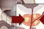
There seems to be no discovery in this at all - the difference between a steam engine and an internal combustion engine lies in the very principle of their operation. Why did steam cars fail to compete with gasoline cars? Because their engines have a number of serious shortcomings.
The first is a well-known fact: there are as many amateur drivers as you like, but there are not a single amateur drivers yet. This area of human activity is occupied exclusively by professionals. The most important thing is that an amateur driver, when getting behind the wheel, risks only his own life and those who voluntarily trusted him; the driver - thousands of others. But something else is also important: servicing a steam engine requires higher qualifications than servicing a gasoline engine. The error results in serious damage and even a boiler explosion.
Second. Who has not seen a steam locomotive rushing along the rails in a white cloud? A cloud is steam released into the atmosphere. A steam locomotive is a powerful machine; there is enough space on it for a large boiler of water. But the car is not enough. And this is one of the reasons for the abandonment of steam engines.
The third and most important thing is the low efficiency of the steam engine. It is not for nothing that in industrially developed countries they are now trying to replace all steam locomotives on highways with heat and electric locomotives; it is not for nothing that the uneconomical nature of a steam locomotive has even become a proverb. 8% - what kind of efficiency is this?
To increase it, you need to increase the temperature and steam pressure. In order for the efficiency of a steam engine with a power of 150 hp or more. With. and above equal to 30% should be maintained operating pressure at 210 kg/cm2, which requires a temperature of 370°. Technically this is feasible, but in general it is extremely dangerous, because even a small leak of steam in the engine or boiler can lead to disaster. And from high pressure The distance to the explosion is very short.
These are the main difficulties. There are also smaller ones (although it must be noted that in technology there are no small things). It is difficult to lubricate the cylinders, because the oil forms an emulsion with hot water and enters the boiler pipes, where it is deposited on the walls. This impairs thermal conductivity and causes severe local overheating. Another “little thing” is that starting a steam engine is more difficult than usual.
And yet, the designers took on something very old and completely new to them. Two amazing machines took to the streets of American cities. Outwardly they were no different from ordinary cars, one even with its streamlined shape resembled a sports one. These were steam cars. Both of them took off in less than 30 seconds. after turning on the engine and reached speeds of up to 160 km/h, ran on any fuel, including kerosene, and consumed 10 gallons of water for 800 kilometers.
In 1966, Ford tested a four-stroke high-speed steam engine for a car with a displacement of 600 cm3. Tests have shown that in exhaust gases contains only 20 hydrocarbon particles per 1 million (27 particles are allowed by the Senate Air Pollution Commission), carbon monoxide contained 0.05% total mass exhaust gases, which is 30 times less than the permissible amount.

An experimental steam car made by General Motors, under the symbol E-101, was demonstrated at an exhibition of cars with unusual engines. Outwardly, it did not differ from the car on the basis of which it was created - the Pontiac - but the engine, together with the boiler, condenser and other components of the steam system, weighed 204 kg more. The driver sat down in his seat, turned the key and waited 30-45 seconds until the light came on. This meant that the steam pressure had reached the required value and we could go. Such a short period of time can be divided into the following stages.
The boiler is full - the fuel pump turns on, fuel enters the combustion chamber and mixes with air.
Ignition.
The temperature and steam pressure have reached the required level, steam goes into the cylinders. The engine is idling.
The driver presses the pedal; the amount of steam going into the engine increases, the car starts moving. Any fuel - diesel, kerosene, gasoline.
All these experiments enabled Robert Ayres of the Washington Advanced Development Center to declare that the shortcomings of the steam car had been overcome. The high cost of mass production will certainly decrease. A boiler consisting of pipes eliminates the risk of explosion, since only a small amount of water is involved in operation at any time. If the pipes are placed closer together, the engine size will decrease. Antifreeze will eliminate the danger of freezing. A steam engine does not need a gearbox, transmission, starter, carburetor, muffler, cooling, gas distribution or ignition systems. This is its huge advantage. The operating mode of the machine can be adjusted by supplying more or less steam to the cylinders. If you use freon instead of water, which freezes at very low temperatures and it also has lubricating properties, then the benefits will increase even more. Steam engines compete with conventional engines in terms of acceleration, fuel consumption, and power per unit of weight.
So far there is no talk of widespread use of steam cars. Not a single car has been brought to the level of industrial design, and no one is going to rebuild the automotive industry. But amateur designers have nothing to do with industrial technology. And one after another they create original examples of cars with steam engines.
Two inventors, Peterson and Smith, redesigned the outboard motor. They supplied steam to the cylinders through spark plug holes. The engine weighing 12 kg developed a power of 220 hp. With. at 5600 rpm. Their example was followed by mechanical engineer Peter Barrett and his son Philip. Using an old chassis, they built a steam car. Smith shared his experience with them. Father and son used a four-cylinder outboard motor, combining it with a steam turbine designed by Smith.
The steam was produced in a specially designed boiler which contains approximately 400 feet of copper and steel tubes, connected into spiral ligaments passing over each other. This increases circulation. Water is pumped into the boiler from the tank. Fuel mixes with air in the combustion chamber, and hot flames come into contact with the pipes. After 10-15 seconds. water turns into compressed steam at a temperature of approximately 350°C and a pressure of 44 kg/cm. It is ejected from the opposite end of the steam generator and directed into the engine intake duct.
Steam enters the cylinder through rotating blades, along which there are channels of constant cross-section.
Outer coupling crankshaft rigidly connected to the chain drive to the drive wheels.
Finally the superheated steam did its job useful work, and it must now turn into water to be ready to start the cycle again. This is done by a capacitor that looks like a regular radiator automobile type. It is placed in front - for better cooling counter currents of air.
The greatest difficulties for engineers lie in the fact that often, in order to achieve at least relative simplicity of design, it is necessary to reduce the already low efficiency of the car. The two amateur designers were greatly helped by the advice of Smith and Peterson. It is as a result collaboration managed to introduce many valuable new products into the design. Let's start with combustion air. Before directly entering the burner, it is heated by passing it between the hot walls of the boiler. This ensures more complete combustion of fuel, reduces exhaust time, and also makes the combustion temperature of the mixture higher and, therefore, efficiency.
To ignite the combustible mixture in a conventional steam boiler, a simple candle is used. Peter Barrett has designed more than effective system - electronic ignition. Rectified alcohol was used as a combustible mixture, since it is cheap and has a high octane number. Of course, kerosene diesel fuel and other liquid varieties will work too.

But the most interesting thing here is the capacitor. Condensation large quantities steam is considered the main difficulty of modern steam power plants. Smith designed the radiator to use water mist. The design works perfectly, the system condenses moisture by 99%. Almost no water is wasted - except for the small amount that does seep through the seals.
Other interesting new product- Lubrication system. The cylinders of a steam engine are usually lubricated by a complex and cumbersome device that sprays heavy oil dust into the steam. The oil settles on the cylinder walls and is then released with the exhaust steam. Later, the oil must be separated from the water condensate and returned to the lubrication system.
The Barretts used a chemical emulsifier that absorbs both water and oil and then separates them, thus eliminating the need for a bulky injector or mechanical separator. Tests show that when the chemical emulsifier operates, no sediment is formed either in the steam boiler or in the condenser.
Also interesting is the clutch type mechanism, which directly connects the engine to the drive shaft and driveline. The machine does not have a gearbox; the speed is controlled by changing the steam intake into the cylinders. Using the intake-exhaust system allows you to easily put the engine in neutral. Steam can be directed to the engine, heat it and at the same time bring the steam boiler into a position ready for active operation, maintaining a constant pressure close to operating pressure. The steam engine develops a power of 30-50 hp. s, and a gallon of fuel is enough to move a car a distance of 15-20 miles, which is quite comparable to the fuel consumption of cars with an internal combustion engine. Control system quite complex, but fully automated; You only have to monitor the steering mechanism and select the required speed. When tested, the car reached speeds of about 50 mph, but this was the limit because the car's chassis was not matched to the engine's power.
This is the result. All this is still experiments. But who knows, we might not witness a new dominance of steam on roads - now not railways, but highways.
R. YAROV, engineer
Modeler-constructor 1971.
Steam locomotives or Stanley Steamer automobiles often come to mind when one thinks of “steam engines,” but the use of these mechanisms is not limited to transportation. Steam engines, which were first created in primitive form about two thousand years ago, have become the largest sources of electrical power over the past three centuries, and today steam turbines produce about 80 percent of the world's electricity. To further understand the nature of the physical forces on which such a mechanism operates, we recommend that you make your own steam engine from ordinary materials using one of the methods suggested here! To get started, go to Step 1.
Steps
Steam engine made from a tin can (for children)
Cut the bottom of the aluminum can to 6.35 cm. Using tin snips, cut the bottom of the aluminum can straight to about a third of the height.
Bend and press the rim using pliers. To avoid sharp edges, bend the rim of the jar inward. When performing this action, be careful not to injure yourself.
Press down on the bottom of the jar from the inside to make it flat. Most aluminum beverage cans will have a round base that curves inward. Level the bottom by pressing down with your finger or using a small, flat-bottomed glass.
Make two holes in opposite sides of the jar, 1/2 inch from the top. Both a paper hole punch and a nail and hammer are suitable for making holes. You will need holes that are just over three millimeters in diameter.
Place a small tea light in the center of the jar. Crumple up the foil and place it under and around the candle to keep it in place. Such candles usually come in special stands, so the wax should not melt and leak into the aluminum jar.
Wrap the central part of a copper tube 15-20 cm long around a pencil 2 or 3 turns to form a coil. The 3mm diameter tube should bend easily around the pencil. You will need enough curved tubing to extend across the top of the jar, plus an extra 5cm of straight pipe on each side.
Insert the ends of the tubes into the holes in the jar. The center of the coil should be located above the candle wick. It is desirable that the straight sections of the tube on both sides of the can be the same length.
Bend the ends of the pipes using pliers to create a right angle. Bend the straight sections of the tube so that they point in opposite directions from different sides of the can. Then again bend them so that they fall below the base of the jar. When everything is ready, you should get the following: the serpentine part of the tube is located in the center of the jar above the candle and turns into two inclined “nozzles” looking in opposite directions on both sides of the jar.
Place the jar in a bowl of water, allowing the ends of the tube to submerge. Your “boat” must stay securely on the surface. If the ends of the tube are not submerged enough, try to weigh the jar down a little, but be careful not to drown it.
Fill the tube with water. The most in a simple way will dip one end into the water and pull from the other end like through a straw. You can also use your finger to block one outlet from the tube and place the other under running water from the tap.
Light a candle. After a while, the water in the tube will heat up and boil. As it turns to steam, it will come out through the "nozzles", causing the entire can to spin around in the bowl.
Paint Can Steam Engine (Adults)
- You need to make sure that this can (and the other one you are using) only contained latex paint, and wash it thoroughly with soapy water before use.
-
Cut a strip of wire mesh 12 x 24 cm. Bend 6 cm along each edge at an angle of 90 o. You will end up with a 12 x 12 cm square “platform” with two 6 cm “legs”. Place it in the jar with the “legs” down, aligning it with the edges of the cut hole.
Make a semicircle of holes around the perimeter of the lid. You will subsequently burn coal in the can to provide heat to the steam engine. If there is a lack of oxygen, coal will burn poorly. To ensure proper ventilation in the jar, drill or punch several holes in the lid that form a semicircle along the edges.
- Ideally, the diameter of the ventilation holes should be about 1 cm.
-
Make a coil from copper tubing. Take about 6 m of soft copper tube with a diameter of 6 mm and measure 30 cm from one end. Starting from this point, make five turns with a diameter of 12 cm. Bend the remaining length of the pipe into 15 turns with a diameter of 8 cm. You should have about 20 cm left .
Pass both ends of the coil through the vent holes in the lid. Bend both ends of the coil so that they point up and pass both through one of the holes in the lid. If the pipe is not long enough, you will need to slightly bend one of the turns.
Place the coil and charcoal in the jar. Place the coil on the mesh platform. Fill the space around and inside the coil with charcoal. Close the lid tightly.
Drill holes for the tube in a smaller jar. Drill a hole with a diameter of 1 cm in the center of the lid of a liter jar. On the side of the jar, drill two holes with a diameter of 1 cm - one near the base of the jar, and the second above it near the lid.
Insert the sealed plastic tube into the side holes of the smaller jar. Using the ends of a copper tube, make holes in the center of the two plugs. Insert a hard plastic tube 25 cm long into one plug, and the same tube 10 cm long into the other plug. They should sit tightly in the plugs and look out a little. Insert the stopper with the longer tube into the bottom hole of the smaller jar and the stopper with the shorter tube into the top hole. Secure the tubes in each plug using clamps.
Connect the tube from the larger jar to the tube from the smaller jar. Place the smaller can over the larger one, with the tube and stopper pointing away from the vent holes of the larger can. Using metal tape, secure the tube from the bottom plug to the tube coming out of the bottom of the copper coil. Then similarly secure the tube from the top plug with the tube coming out of the top of the coil.
Insert the copper tube into the junction box. Using a hammer and screwdriver, remove the center portion of the round metal electrical box. Secure the electrical cable clamp with the locking ring. Insert 15 cm of 1.3 cm diameter copper tubing into the cable clamp so that the tube extends a few centimeters below the hole in the box. Bend the edges of this end inward using a hammer. Insert this end of the tube into the hole in the lid of the smaller jar.
Insert the skewer into the dowel. Take a regular wooden barbecue skewer and insert it into one end of a hollow wooden dowel that is 1.5 cm long and 0.95 cm in diameter. Insert the dowel and skewer into the copper tube inside the metal junction box with the skewer facing up.
- While our motor is running, the skewer and dowel will act as a "piston". To make the movements of the piston better visible, you can attach a small paper “flag” to it.
-
Prepare the engine for operation. Remove the junction box from the smaller top jar and fill the top jar with water, allowing it to pour into the copper coil until the jar is 2/3 full of water. Check for leaks at all connections. Secure the lids of the jars tightly by tapping them with a hammer. Reinstall the junction box in place above the smaller top can.
-
Start the engine! Crumple up pieces of newspaper and place them in the space under the screen at the bottom of the engine. Once the charcoal is lit, let it burn for about 20-30 minutes. As the water in the coil heats up, steam will begin to accumulate in the top jar. When the steam reaches enough pressure, it will push the dowel and skewer to the top. After the pressure is released, the piston will move downwards under the influence of gravity. If necessary, cut off part of the skewer to reduce the weight of the piston - the lighter it is, the more often it will “float”. Try to make a skewer of such weight that the piston “moves” at a constant pace.
- You can speed up the combustion process by increasing the air flow into the vents with a hairdryer.
-
Stay safe. We believe it goes without saying that care must be taken when working and handling a homemade steam engine. Never run it indoors. Never run it near flammable materials such as dry leaves or overhanging tree branches. Only use the engine on a solid, non-flammable surface such as concrete. If you work with children or teenagers, they should not be left unattended. Children and teenagers are prohibited from approaching the engine when charcoal is burning in it. If you don't know the temperature of the engine, assume it is too hot to touch.
- Make sure that steam can escape from the top "boiler". If for any reason the plunger gets stuck, pressure can build up inside the smaller can. In the worst case scenario, the bank could explode, which Very dangerous.
Cut a rectangular hole near the base of a 4-quart paint can. Make a horizontal 15cm x 5cm rectangular hole in the side of the jar near the base.
- Place the steam engine in a plastic boat, dipping both ends into the water to create a steam toy. You can cut a simple boat shape from plastic bottle soda or bleach to make your toy more environmentally friendly.
But in fact, this applies not so much to the car brand, but to the people who founded it. The Doble brothers, Abner and John, already in 1910 managed to combine ancient technology with advanced stylistic solutions. However, they also had to significantly improve this technology. John did this while studying at the Massachusetts Institute of Technology - even then the talented engineer could afford to maintain a personal workshop in which he tested a unique capacitor own development. The device was intended to condense exhaust steam and was made in the form of a honeycomb radiator. With this innovation, the prototype traveled up to 2,000 kilometers on 90 liters of water, exceeding the standard mileage of a “ferry car” by almost 20 times!
For its time it was a sensation. After the hype in the press, the brothers immediately acquired investors, whose funds were sufficient to establish General company Engineering with an authorized capital of $200 thousand. All further developments and improvements to steam cars were carried out there.
1 / 5
2 / 5
3 / 5
4 / 5
5 / 5
For the 1917 New York Auto Show concept, John Doble, the venture's biggest head, came up with an electric ignition system in which pressurized kerosene was forced through the carburetor and ignited by a spark plug.
Then the burning mixture entered the combustion chamber, where it heated the water in the boiler. The process was started with one press of a button, and the engine only needed 90 seconds to reach the desired level of steam pressure and start the car! All these mythical characteristics made the Doblov steam car perhaps the most striking premiere - by the end of the year, General Engineering received more than 5 thousand orders from customers. If it weren’t for the First World War, which deprived the company of iron, who knows what we would be driving now...
In 1921, John dies after a serious illness. However, two other brothers immediately take his place - the Doblov family turned out to be unusually large. Soon Abner, Bill and Warren create new brand. then he spends another hour outside, where the frost gets stronger. Then, in front of the specialists, the ignition is activated, the engine starts, and after 23 seconds the car can drive.
The top speed of the Model E was then 160 km/h, and it accelerated to hundreds in just 8 seconds! This happened thanks to a new four-cylinder engine, in which steam was first delivered to two high-pressure cylinders, and the residual energy was received by two low-pressure cylinders, which sent “empty” steam to the condenser. Eureka, no less!
1 / 7
2 / 7
3 / 7
4 / 7
5 / 7
6 / 7
7 / 7
Of course, subtle technical solutions required the best materials, which had a corresponding impact on the final price tag. Thus, a steam car produced by Doble Steam Motors with reliable Bosch electrics on board and a luxurious interior lined with wood and even ivory cost $18,000. Considering Ford’s $800 Iron Lizzie, which was then in good condition, this was obscenely expensive. This means that either large industrialists or bank robbers could afford to ride on the perfect steam car. It's a pity that the latter also preferred Ford. If he knew even a little about cars, perhaps Doble Steam Motors would not have ceased to exist in 1931, having released only 50 production copies to the market.
Peculiarities:
The Doble brothers were not credited with inventing the steam engine. They succeeded in another way, making a steam car a modern, fast and comfortable means of transportation. Howard Hughes himself drove the Model E, which already says a lot. In addition, the power plant produced by Doble Steam Motors did not disappear without a trace: in 1933 it was successfully tested by the aviation company Bessler. A little later, Johnston's steam airplane also distinguished itself by its silent flight and low landing speed. This means that advanced ideas can reach heaven during our lifetime...
The best of the "worst"
Another striking example of family cohesion was shown to the world by the Stanley brothers, who built the steam-powered Rocket in 1906. This device was born with the sole purpose of setting a speed record. The machine was powered by a two-cylinder steam unit horizontal arrangement, whose maximum power reached 150 hp! This ferry car borrowed its exotic appearance from Indian canoes - the sharp, streamlined silhouette allowed the engineers to achieve incredible aerodynamic performance. Over time, it was adopted by all racers who were at least somehow related to common sense.
1 / 2
2 / 2
Only one person dared to pilot such extreme technology, Fred Marriott. Bonneville Salt Lake was not yet popular among racers, so Ormond Beach, located near Daytona Beach in Florida, was used for record-breaking races. On the first try, the Stanley Brothers' Rocket exceeded the speed limit of 205 km/h for a 1-mile ride and 195 km/h for a 1-km ride (measured within that mile). At that time no one could achieve such an indicator. This was the hour of true triumph for the Stanley brothers and all steam technology!
A year later, a team of crazy experimenters Stanley Rocket set out to speed up their car. After all, the potential of this steam force was not fully revealed - so they believed. Having aimed at a speed limit of 322 km/h (200 mph), they increased the engine power, solving this issue by increasing the steam pressure. As a result, the cylinders received a pressure of 90 bar, and the car itself acquired a more powerful braking system.
1 / 5
2 / 5
3 / 5
4 / 5
5 / 5
Structurally, Stanley’s “Rocket” could withstand all the loads and would have withstood it if there had been a perfectly flat surface under its wheels. The disastrous result almost cost Fred Marriott his life - the car bounced on a bump and fell apart in pieces. After this, the Stanley brothers suspended their experiments. Not for long...
Peculiarities:
The scandal fanned by newspapermen around the defeat of Stanley Rocket almost overshadowed its own triumph. Many tried to take the height, which the steam “Rocket” easily conquered. Until recently, many spears, axes and other weapons were broken on her record, which other loser racers threw at the winner out of anger. And steam power still rules!
Truck on wood
And also on coal and even peat! Yes, such phrases did not arise out of nowhere - and of course. But oddly enough, the comic metaphor in 1948 - in an era of total shortages and austerity - was brought to life and worked! The country devastated by World War II had to be raised, industrialized, and provided for. Therefore, following the Resolution of the Council of Ministers of the USSR of 08/07/1947 “On the mechanization of logging and the development of new forest areas,” NAMI was instructed to develop power unit and the design of a timber truck that would run on wood. Well, everything seems to be logical - in the vast forest belt there is a lot of fuel...
1 / 5
2 / 5
3 / 5
4 / 5
5 / 5
Already in May 1949, the group of engineers leading the project, headed by Yuri Shebalin and Nikolai Korotonoshko, received an author's certificate for a steam engine that ran on low-calorie fuel. The high-pressure steam power plant was equipped with a water-tube boiler with natural circulation and a 3-cylinder single-expansion engine. The refueling material, the so-called “firewood” (medium-sized pellets), was loaded into two fuel bunkers located on top of each other and entered the burner “self-propelled” as it burned. This process could be regulated manually or automatically - three gear positions provided for 20%, 40% and 75% filling of the engine cylinder. Thus, the cruising range of the experimental NAMI-012 truck was 80-120 km.
By the time the testing of the wood-burning tractor prototypes was completed, that is, in the summer of 1951, the production of steam-powered vehicles had ceased all over the world. The opinion of the supervisory commission, which included representatives of almost all automotive organizations, was also not in favor of NAMI-012. Loaded vehicles showed excellent cross-country ability, but when running empty, problems emerged - all due to overload of the front axle.
1 / 5
2 / 5
3 / 5
4 / 5
5 / 5
Then it was decided to continue research and make an all-wheel drive prototype. The index NAMI-018 was assigned to it. Externally, it differed from its predecessor only in its vertical grille engine compartment. The engineers managed to stabilize the empty tractor, but there were still more disadvantages to its operation than advantages. In order to travel the “ill-fated” 100 km, the truck had to carry almost half a ton of firewood, prepared for future use and already dried. At the same time, in winter it was necessary to drain the water at night (as much as 200 liters) so that it would not freeze and burst the boiler from the inside, and then fill it again in the morning. In 1954, when the Soviets gained access to oil, and therefore cheap liquid fuel, such sacrifices were no longer justified.
Peculiarities:
The commission’s verdict, which stated “The NAMI-018 steam vehicle meets all the parameters of the forestry industry, but can only be used in areas where delivery of liquid fuel is difficult or high in cost,” actually sentenced the wood-burning tractor to death. The few prototypes were mercilessly destroyed, even the secret NAMI-012B, which could run on fuel oil alone. All that remains of them today are a few photographs, blurred due to the ever-smoking steam engine...
Kit cars don't give a damn
Australia is a desperate country after all. Either there is a lot of sun there, or there are funny animals. Or are it just crazy ideas floating around in the salty air and getting to enthusiasts for free... The latter, for example, will take it and organize races simply out of boredom. Oh well, they’ll arrange it, and they’ll also find money for their project somewhere! Moreover, not only indigenous Australians are subject to such processes, but also visitors, like the Englishman Peter Pellandine, who carved a couple of super-light kit cars out of fiberglass, and then for some reason decided to attach a steam engine to them...
Steam engines were used as drive engines in pumping stations, locomotives, steam ships, tractors, steam cars and other vehicles. Steam engines contributed to the widespread commercial use of machines in enterprises and were the energy basis of the industrial revolution of the 18th century. Later, steam engines were replaced by internal combustion engines, steam turbines, electric motors and nuclear reactors, which are more efficient.
Steam engine in action
Invention and development
The first known device driven by steam was described by Heron of Alexandria in the first century - this is the so-called “Heron's bath”, or “aeolipil”. Steam escaping tangentially from the nozzles attached to the ball caused the latter to rotate. It is assumed that the conversion of steam to mechanical movement was known in Egypt during the period of Roman rule and was used in simple devices.
First industrial engines
None of the devices described have actually been used as a means of solving useful problems. The first steam engine used in production was the “fire engine”, designed by the English military engineer Thomas Savery in 1698. Savery received a patent for his device in 1698. It was a piston steam pump, and obviously not very efficient, since the heat of the steam was lost each time during cooling of the container, and quite dangerous to operate, since due to the high steam pressure, the containers and engine pipelines sometimes exploded. Since this device could be used both to rotate the wheels of a water mill and to pump water out of mines, the inventor called it “the miner’s friend.”
Then the English blacksmith Thomas Newcomen demonstrated his “ naturally aspirated engine", which was the first steam engine for which there could be a commercial demand. This was Savery's improved steam engine, in which Newcomen significantly reduced the operating steam pressure. Newcomen may have been based on descriptions of Papin's experiments held at the Royal Society of London, to which he may have had access through society member Robert Hooke, who had worked with Papen.

Diagram of the operation of Newcomen's steam engine.
– Steam is shown in purple, water in blue.
– Open valves shown green, closed - red
The first use of the Newcomen engine was to pump water from a deep mine. In a mine pump, the rocker arm was connected to a rod that went down into the shaft to the pump chamber. The reciprocating movements of the thrust were transmitted to the pump piston, which supplied water upward. The valves of early Newcomen engines were opened and closed manually. The first improvement was the automation of the valves, which were driven by the machine itself. Legend tells that this improvement was made in 1713 by the boy Humphrey Potter, who was supposed to open and close the valves; when he got tired of it, he tied the valve handles with ropes and went to play with the children. By 1715, a lever control system had already been created, driven by the mechanism of the engine itself.
Russia's first two-cylinder vacuum steam engine was designed by mechanic I. I. Polzunov in 1763 and built in 1764 to drive blowers at the Barnaul Kolyvano-Voskresensk factories.
Humphrey Gainsborough built a model of a steam engine with a condenser in the 1760s. In 1769, Scottish mechanic James Watt (possibly using Gainsborough's ideas) patented the first significant improvements to the Newcomen vacuum engine, which made it significantly more fuel efficient. Watt's contribution was to separate the condensation phase of the vacuum engine in a separate chamber while the piston and cylinder were at steam temperature. Watt added a few more important details to Newcomen's engine: he placed a piston inside the cylinder to push out steam and converted the reciprocating motion of the piston into the rotational motion of a drive wheel.
Based on these patents, Watt built a steam engine in Birmingham. By 1782, Watt's steam engine was more than 3 times more productive than Newcomen's engine. The improvement in the efficiency of Watt's engine led to the use of steam power in industry. In addition, unlike Newcomen's engine, Watt's engine allowed rotational motion to be transmitted, while in early models of steam engines the piston was connected to a rocker arm rather than directly to a connecting rod. This engine already had the basic features of modern steam engines.
A further increase in efficiency was the use of high-pressure steam (American Oliver Evans and Englishman Richard Trevithick). R. Trevithick successfully built industrial high-pressure single-stroke engines known as "Cornish engines". They operated at a pressure of 50 psi, or 345 kPa (3.405 atmospheres). However, with increasing pressure, there was also a greater danger of explosions in machines and boilers, which initially led to numerous accidents. From this point of view, the most important element high pressure machine was safety valve, which released excess pressure. Reliable and safe operation began only with the accumulation of experience and standardization of procedures for the construction, operation and maintenance of equipment.
French inventor Nicolas-Joseph Cugnot demonstrated the first working self-propelled steam vehicle in 1769: the "fardier à vapeur" (steam cart). Perhaps his invention can be considered the first automobile. The self-propelled steam tractor turned out to be very useful as a mobile source of mechanical energy that drove other agricultural machines: threshers, presses, etc. In 1788, a steamboat built by John Fitch was already providing regular service along the Delaware River between Philadelphia (Pennsylvania) and Burlington (New York State). It carried 30 passengers and traveled at a speed of 7-8 miles per hour. J. Fitch's steamship was not commercially successful because its route was competing with a good overland road. In 1802, Scottish engineer William Symington built a competitive steamboat, and in 1807, American engineer Robert Fulton used Watt's steam engine to power the first commercially successful steamship. On 21 February 1804, the first self-propelled railway steam locomotive, built by Richard Trevithick, was demonstrated at the Penydarren Ironworks at Merthyr Tydfil in South Wales.
Reciprocating steam engines
Reciprocating engines use steam power to move a piston in a sealed chamber or cylinder. The reciprocating action of the piston can be mechanically converted into linear motion piston pumps or in rotational motion to drive rotating parts of machine tools or wheels of vehicles.
Vacuum machines
Early steam engines were initially called "fire engines" and also Watt's "atmospheric" or "condensing" engines. They worked on the vacuum principle and are therefore also known as " vacuum motors" Such machines worked to drive piston pumps, in any case, there is no evidence that they were used for other purposes. When a vacuum-type steam engine operates, at the beginning of the stroke, low-pressure steam is admitted into the working chamber or cylinder. The inlet valve then closes and the steam cools by condensing. In a Newcomen engine, cooling water is sprayed directly into the cylinder and the condensate drains into a condensate collector. This creates a vacuum in the cylinder. Atmospheric pressure at the top of the cylinder presses on the piston and causes it to move downward, that is, the working stroke.
Constantly cooling and reheating the working cylinder of the machine was very wasteful and inefficient, however, these steam engines made it possible to pump water from greater depths than was possible before their introduction. In the year a version of the steam engine appeared, created by Watt in collaboration with Matthew Boulton, the main innovation of which was the removal of the condensation process into a special separate chamber (condenser). This chamber was placed in a bath of cold water, and was connected to the cylinder by a tube closed by a valve. A special small vacuum pump (a prototype of a condensate pump) was attached to the condensation chamber, driven by a rocker arm and used to remove condensate from the condenser. The resulting hot water was supplied by a special pump (a prototype of the feed pump) back to the boiler. Another radical innovation was the closure top end working cylinder, in the upper part of which there was now low pressure steam. The same steam was present in the double jacket of the cylinder, maintaining its constant temperature. As the piston moved upward, this steam was transferred through special tubes to the lower part of the cylinder in order to undergo condensation during the next stroke. The machine, in fact, ceased to be “atmospheric”, and its power now depended on the pressure difference between the low-pressure steam and the vacuum that could be obtained. In Newcomen's steam engine, the piston was lubricated with a small amount of water poured on top of it; in Watt's machine, this became impossible, since there was now steam in the upper part of the cylinder; it was necessary to switch to lubrication with a mixture of grease and oil. The same lubricant was used in the cylinder rod seal.
Vacuum steam engines, despite the obvious limitations of their efficiency, were relatively safe and used low-pressure steam, which was quite consistent with the general low level of boiler technology in the 18th century. The power of the machine was limited by low steam pressure, the size of the cylinder, the rate of fuel combustion and evaporation of water in the boiler, as well as the size of the condenser. The maximum theoretical efficiency was limited by the relatively small temperature difference on both sides of the piston; it did vacuum machines, intended for industrial use, are too large and expensive.
Compression
The outlet window of the steam engine cylinder closes slightly before the piston reaches its extreme position, which leaves some waste steam in the cylinder. This means that in the work cycle there is a compression phase, which forms a so-called “steam cushion”, slowing down the movement of the piston in its extreme positions. In addition, this eliminates sharp drop pressure at the very beginning of the intake phase, when fresh steam enters the cylinder.
Advance
The described “steam cushion” effect is also enhanced by the fact that the intake of fresh steam into the cylinder begins somewhat earlier than the piston reaches its extreme position, that is, there is some advance of the intake. This advance is necessary so that before the piston begins its working stroke under the influence of fresh steam, the steam would have time to fill the dead space that arose as a result of the previous phase, that is, the intake-exhaust channels and the cylinder volume unused for the movement of the piston.
Simple extension
Simple expansion assumes that the steam only works when it is expanded in the cylinder, and the exhaust steam is released directly into the atmosphere or enters a special condenser. The residual heat of the steam can be used, for example, to heat a room or vehicle, as well as to preheat the water entering the boiler.
Compound
During the process of expansion in the cylinder of a high-pressure machine, the temperature of the steam drops in proportion to its expansion. Since there is no heat exchange (adiabatic process), it turns out that the steam enters the cylinder at a higher temperature than it leaves it. Such temperature changes in the cylinder lead to a decrease in the efficiency of the process.
One of the methods of dealing with this temperature difference was proposed in 1804 by the English engineer Arthur Woolf, who patented Wulf high pressure compound steam engine. In this machine, high-temperature steam from a steam boiler entered a high-pressure cylinder, and then the steam exhausted from it at a lower temperature and pressure entered the low-pressure cylinder (or cylinders). This reduced the temperature difference in each cylinder, which overall reduced temperature losses and improved the overall coefficient useful action steam engine. Low pressure steam had a larger volume and therefore required a larger cylinder volume. Therefore, in compound machines, low-pressure cylinders had a larger diameter (and sometimes longer) than high-pressure cylinders.
This arrangement is also known as “double expansion” because the expansion of the steam occurs in two stages. Sometimes one high-pressure cylinder was connected to two low-pressure cylinders, resulting in three cylinders of approximately equal size. This scheme was easier to balance.
Double cylinder compounding machines can be classified as:
- Cross compound- The cylinders are located nearby, their steam-conducting channels are crossed.
- Tandem compound- The cylinders are arranged in series and use one rod.
- Angular compound- The cylinders are located at an angle to each other, usually 90 degrees, and work on one crank.
After the 1880s, compound steam engines became widespread in manufacturing and transportation and became virtually the only type used on steamships. Their use on steam locomotives did not become so widespread because they turned out to be too complex, partly due to the difficult operating conditions of steam engines in railway transport. Although compound steam locomotives never became a widespread phenomenon (especially in the UK, where they were very little common and were not used at all after the 1930s), they gained some popularity in several countries.
Multiple expansion

Simplified diagram of a triple expansion steam engine.
High pressure steam (red) from the boiler passes through the machine, exiting to the condenser at low pressure (blue).
A logical development of the compound scheme was the addition of additional expansion stages to it, which increased the efficiency of work. The result was a multiple expansion scheme known as triple or even quadruple expansion machines. Such steam engines used a series of double-acting cylinders, the volume of which increased with each stage. Sometimes, instead of increasing the volume of low-pressure cylinders, increasing their number was used, just as on some compound machines.
The image on the right shows the operation of a triple expansion steam engine. Steam passes through the machine from left to right. The valve block of each cylinder is located to the left of the corresponding cylinder.
The emergence of this type of steam engine became especially relevant for the fleet, since the size and weight requirements for ship engines were not very strict, and most importantly, this design made it easy to use a condenser that returns waste steam in the form of fresh water back to the boiler (use salted sea water it was impossible to power the boilers). Land-based steam engines usually did not have problems with water supply and therefore could release waste steam into the atmosphere. Therefore, such a scheme was less relevant for them, especially taking into account its complexity, size and weight. The dominance of multiple expansion steam engines only ended with the advent and widespread use of steam turbines. However, in modern steam turbines The same principle of dividing the flow into high, medium and low pressure cylinders is used.
Direct flow steam engines
Once-through steam engines arose as a result of an attempt to overcome one of the disadvantages inherent in steam engines with traditional steam distribution. The fact is that steam in a conventional steam engine constantly changes the direction of its movement, since the same window on each side of the cylinder is used for both the intake and exhaust of steam. When the exhaust steam leaves the cylinder, it cools its walls and steam distribution channels. Fresh steam, accordingly, spends a certain amount of energy on heating them, which leads to a drop in efficiency. Once-through steam engines have an additional window, which is opened by the piston at the end of each phase, and through which the steam leaves the cylinder. This increases the efficiency of the machine because the steam moves in one direction and the temperature gradient of the cylinder walls remains more or less constant. Direct-flow single expansion machines show approximately the same efficiency as compound machines with conventional steam distribution. In addition, they can operate at higher speeds, and therefore, before the advent of steam turbines, they were often used to drive electric generators that required high rotation speeds.
Direct-flow steam engines are available in both single- and double-acting types.
Steam turbines
A steam turbine consists of a series of rotating disks mounted on a single axis, called a turbine rotor, and a series of alternating stationary disks mounted on a base, called a stator. The rotor disks have blades on the outside; steam is supplied to these blades and spins the disks. The stator disks have similar blades mounted at opposite angles, which serve to redirect the flow of steam to the following rotor disks. Each rotor disk and its corresponding stator disk are called a turbine stage. The number and size of stages of each turbine are selected in such a way as to maximize the useful energy of the steam of the speed and pressure that is supplied to it. The exhaust steam leaving the turbine enters the condenser. Turbines rotate with very high speed, and therefore, when transferring rotation to other equipment, special reduction transmissions are usually used. In addition, turbines cannot change the direction of their rotation, and often require additional reverse mechanisms (sometimes additional reverse rotation stages are used).
Turbines convert steam energy directly into rotation and do not require additional mechanisms to convert reciprocating motion into rotation. In addition, turbines are more compact than reciprocating machines and have a constant force on the output shaft. Since turbines have more simple design, they tend to require less maintenance.
Other types of steam engines
Application
Steam engines can be classified according to their application as follows:
Stationary machines

Steam hammer

Steam engine in an old sugar factory, Cuba
Stationary steam engines can be divided into two types according to their mode of use:
- Variable-mode machines, which include rolling mill machines, steam winches and similar devices, which must frequently stop and change direction of rotation.
- Power machines that rarely stop and should not change direction of rotation. These include energy motors in power plants, as well as industrial motors used in factories, factories, and cable railroads before the widespread adoption of electric traction. Engines low power used on ship models and in special devices.
A steam winch is essentially a stationary engine, but is mounted on a support frame so that it can be moved. It can be secured with a cable to an anchor and moved by its own traction to a new location.
Transport vehicles

Steam engines were used to drive various types vehicles, among them:
- Land vehicles:
- Steam car
- Steam tractor
- Steam shovel, and even
- Steam plane.
In Russia, the first operating steam locomotive was built by E. A. and M. E. Cherepanov at the Nizhny Tagil plant in 1834 to transport ore. It reached a speed of 13 versts per hour and carried more than 200 poods (3.2 tons) of cargo. The length of the first railway was 850 m.
Advantages of steam engines
The main advantage of steam engines is that they can use almost any heat source to convert it into mechanical work. This distinguishes them from internal combustion engines, each type of which requires the use of a specific type of fuel. This advantage is most noticeable in the use of nuclear energy, since a nuclear reactor is unable to generate mechanical energy, but only produces heat, which is used to generate steam to drive steam engines (usually steam turbines). In addition, there are other heat sources that cannot be used in internal combustion engines, such as solar energy. An interesting direction is the use of energy from temperature differences in the World Ocean at different depths.
Similar properties are also possessed by other types of external combustion engines, such as the Stirling engine, which can provide very high efficiency, but have significantly greater weight and size than modern types of steam engines.
Steam locomotives perform well at high altitudes, since their operating efficiency does not decrease due to low atmospheric pressure. Steam locomotives are still used in the mountainous regions of Latin America, despite the fact that in the lowlands they have long been replaced by more modern types of locomotives.
In Switzerland (Brienz Rothorn) and Austria (Schafberg Bahn), new steam locomotives using dry steam have proven their efficiency. This type of locomotive was developed based on the Swiss Locomotive and Machine Works (SLM) models, with many modern improvements such as the use of roller bearings, modern thermal insulation, burning of light petroleum fractions as fuel, improved steam lines, etc. . As a result, such locomotives have 60% lower fuel consumption and significantly lower maintenance requirements. Economic qualities These locomotives are comparable to modern diesel and electric locomotives.
In addition, steam locomotives are much lighter than diesel and electric ones, which is especially important for mining railways. A special feature of steam engines is that they do not require a transmission, transmitting power directly to the wheels.
Efficiency
A steam engine releasing steam to the atmosphere will have a practical efficiency (including the boiler) of 1 to 8%, but an engine with a condenser and expansion of the flow path can improve the efficiency to 25% or even more.
The reason for the construction of this unit was a stupid idea: “is it possible to build a steam engine without machines and tools, using only parts that can be bought in a store” and do everything with your own hands. The result is a design like this. The entire assembly and setup took less than an hour. Although it took six months to design and select parts.
Most of the structure consists of plumbing fixtures. At the end of the epic, the questions from sellers of hardware and other stores: “can I help you” and “why do you need them” really infuriated me.
And so we assemble the foundation. First the main cross member. Tees, bochata, and half-inch angles are used here. I secured all the elements with sealant. This is to make it easier to connect and separate them with your hands. But for final assembly it is better to use plumber's tape. 
Then the longitudinal elements. The steam boiler, spool, steam cylinder and flywheel will be attached to them. Here all the elements are also 1/2". 
Then we make the stands. In the photo, from left to right: a stand for the steam boiler, then a stand for the steam distribution mechanism, then a stand for the flywheel, and finally a holder for steam cylinder. The flywheel holder is made from a 3/4" tee (external thread). Bearings from a repair kit for roller skates are ideally suited to it. The bearings are held in place by a coupling nut. Such nuts can be found separately or taken from a tee for metal-plastic pipes. This tee is pictured in the bottom right corner (not used in the design). A 3/4" tee is also used as a holder for the steam cylinder, only the threads are all internal. Adapters are used to attach 3/4" to 1/2" elements. 
We assemble the boiler. A 1" pipe is used for the boiler. I found a used one on the market. Looking ahead, I want to say that the boiler turned out to be small and does not sufficient quantity pair. With such a boiler, the engine runs too sluggishly. But it works. The three parts on the right are: a plug, a 1"-1/2" adapter and a squeegee. The squeegee is inserted into the adapter and closed with a plug. This way the boiler becomes airtight. 
This is how the boiler turned out initially. 
But the steam tank turned out to be not high enough. Water got into the steam line. I had to install an additional 1/2" barrel through an adapter. 
This is a burner. Four posts earlier there was the material “Homemade oil lamp from pipes”. This is how the burner was originally designed. But no suitable fuel was found. Lamp oil and kerosene smoke heavily. Need alcohol. So for now I just made a holder for dry fuel. 
This is very important detail. Steam distributor or spool. This thing directs steam into the slave cylinder during the power stroke. When the piston moves in reverse, the steam supply is shut off and a discharge occurs. The spool is made from a cross for metal-plastic pipes. One of the ends must be sealed with epoxy putty. This end will be attached to the rack through an adapter. 
And now the most important detail. It will determine whether the engine will start or not. This is the working piston and spool valve. Here we use an M4 pin (sold in furniture fittings departments; it’s easier to find one long one and saw off the required length), metal washers and felt washers. Felt washers are used for fastening glass and mirrors with other fittings. 
Felt is not the best material. It does not provide sufficient tightness, but the resistance to movement is significant. Later we managed to get rid of the felt. Non-standard washers were ideal for this: M4x15 for the piston and M4x8 for the valve. These washers need to be placed as tightly as possible, through plumbing tape, onto a pin and with the same tape wound 2-3 layers from the top. Then thoroughly rub in the cylinder and spool with water. I didn't take a photo of the upgraded piston. Too lazy to take it apart. 
This is the actual cylinder. Made from a 1/2" barrel, it is secured inside a 3/4" tee with two coupling nuts. On one side, with maximum sealing, the fitting is tightly attached. 
Now the flywheel. The flywheel is made from a dumbbell plate. IN central hole a stack of washers is inserted, and a small cylinder from a repair kit for roller skates. Everything is secured with sealant. A furniture and picture hanger was ideal for the carrier holder. Looks like a keyhole. Everything is assembled in the order shown in the photo. Screw and nut - M8. 
We have two flywheels in our design. There must be a strong connection between them. This connection is ensured by a coupling nut. All threaded connections are secured with nail polish. 
These two flywheels appear the same, however one will be connected to the piston and the other to the spool valve. Accordingly, the carrier, in the form of an M3 screw, is attached at different distances from the center. For the piston, the carrier is located further from the center, for the valve - closer to the center. 
Now we make the valve and piston drive. The furniture connection plate was ideal for the valve. 
The piston uses the window lock escutcheon as a lever. She came up like family. Eternal glory to whoever invented the metric system. 
Drives assembled. 
Everything is installed on the engine. Threaded connections are secured with varnish. This is the piston drive. 
Valve drive. Please note that the positions of the piston carrier and valve differ by 90 degrees. Depending on which direction the valve carrier leads the piston carrier, it will depend on which direction the flywheel will rotate. 
Now all that remains is to connect the tubes. These are silicone hoses for aquariums. All hoses must be secured with wire or clamps.
It should be noted that there is no safety valve provided here. Therefore, extreme caution should be taken. 
Voila. Fill with water. Let's set it on fire. We are waiting for the water to boil. During heating, the valve must be in the closed position. 
The entire assembly process and the result are on video.