The first microcar "Mouse" I built for my children. How successful he was, readers of the "Model Designer" can judge by reading his description and drawings published in "".
As a result, I gained some design experience and conceived not a children's, but an "adult" car - for myself. He called her "Mouse-2". He built for a long time, or rather, not so much built as he was looking for the necessary parts, assemblies. This, in particular, explains the use of mechanical brakes in Mouse-2 (now I am changing them to hydraulic ones). The development of drawings and construction were carried out simultaneously, although the main parameters of the "Mouse-2" were thought out by me in advance.
Let me give you a brief technical description. This is a two-seater four-wheeled car with a 14 hp engine. With. (working volume 346 cm 3), located at the back. Equipped with two independent brake systems: main (working) with pedal drive to all wheels and spare (parking) with lever drive to rear wheels only.
The car is dynamic and stable. The braking distance at a speed of 30 km/h is not more than 6.5 m. The smallest turning radius along the outer wheel track axis is 4.5 m. The maximum speed is 65 km/h.
Electrical equipment - from the S3D motorized stroller, 12-volt, slightly modified. It includes devices for external lighting and light signaling, a sound signal, a windshield wiper, instrumentation.
The salon is finished with modern materials, isolated from the engine compartment with a noise-absorbing panel with foam filler. The driver and passenger seats are anatomical, glued from fiberglass, lined with foam rubber and trimmed with leatherette; the machine is equipped with seat belts.

The car has been in operation since May 1985. There are already many thousands of kilometers of Sakhalin roads on the speedometer. There were no major breakdowns along the way. True, I must note that when fully loaded, the engine power is not enough to overcome the steep and protracted climbs that are often encountered on our roads. And this forces you to turn on the first gear. I am also critical of the doors that open upwards - they are not convenient in everything. Otherwise, I'm happy with the car.
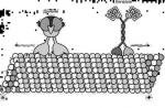
Now I would like to talk about the design features of the "Mouse-2".

1 - front buffers,
2 - sidelights - direction indicators,
3 - retractable headlights with covers,
4 - battery,
5 - front axle,
6 - steering shaft,
7 - luggage compartment,
8 - brake and clutch pedals,
9 - gas pedal,
10 - hand brake handle,
11 - shift and reverse lever,
12 - driver's seat,
13 - headlight lift,
14 - "coins" of the decompressor and corrector,
15 - fuel cock valve,
16 - differential with reverse gear,
17 - drive chain,
18 - engine,
19 - fuel tank,
20 - mufflers,
21 - rear buffer,
22 - rear lights.
It is assembled mainly from spare parts of "Zaporozhets" and sidecars SZA and SZD. The body is framed, with fiberglass panels on a tubular base. The rear hood is hinged or removable, which provides free access to the engine. The body is the most time-consuming part, three-quarters of the time was spent on its assembly and equipment.
First, I made a life-size model of the body. I used pure plaster. To save money, I first laid concrete on the grid, and when it set, I applied a layer of gypsum 15-20 cm thick on top. I sanded and painted the completely dried surface of the model with nitro enamel. The processing was carried out very carefully, so that the flaws did not pass to the matrices.
Then I marked out the panel split lines. In order for them to be clearly printed on the matrices, I drew them with an awl to a depth of about 1 mm. The finished panels were adjusted to them.
Typically, matrices are made of fiberglass. But I needed to save resin and fiberglass, and I had to cast them, like the model, from plaster and concrete.

Rice.3. Typical panel docking scheme:
1 - core pipe,
2 - wooden rail-liner with a groove,
3 - fiberglass pads,
4 - sealing the joint of panels with fiberglass,
5 - panel,
I removed the horseflies of each panel separately: I rubbed the surface of the model with a thin layer of petroleum jelly or grease and washed it down with gypsum, overlapping the parting lines by 10-11 mm, and then with concrete, reinforcing it with steel bars 0 5 mm. To obtain casts from vertical surfaces, he made formwork from boards and plywood.
After the concrete had dried (after about three days), I removed the matrices, dried the gypsum layer, carefully processed and painted.
The main load-bearing panels were glued from six layers of fiberglass with a lining of two layers of glass mat, which gave a thickness of about 4 mm. Before that, the fiberglass was burned with a solder pump flame so that it better absorbed the resin. He burned with great care, as the fabric crumbles in places of burns.

Due to the fact that the glue thickens quickly, it was necessary to prepare it in small portions. Ingredients: epoxy resin (100 cm3), plasticizer (10 cm3) and hardener (10 cm3). You can do without a plasticizer. If the resin is too thick, acetone or solvents No. 646 or No. 648 can be added to it (no more than 10% of the total volume). However, given that such additives somewhat reduce the strength of the product, they should be used as a last resort.
To obtain the desired color, a dye is introduced into the resin - an ordinary art oil paint from a tube (before adding a hardener).

Fig.5. The main power elements of the body:
1 - front buffers,
2 - front axle (steering gear and suspension arms are not shown),
3 - car frame,
4 - edging of the luggage compartment,
5 - front supports of the body frame,
6 - core pipes,
7 - lower supports of the skeleton,
8 - door bar,
9 - door frame,
10 - door hinges,
11 - rear supports of the frame,
12 - hood frame,
13 - hood hinges,
14 - rear buffer.
Before gluing the panels, I cut the fiberglass in layers with a knife on a sheet of plywood (linoleum) and stacked the pieces. Glued in one go with short breaks for rest or breeding a new portion.
After laying the last layer of fiberglass in the matrix, I covered everything with plastic wrap and, having made the formwork, covered the surface with sand. A day later, he removed the sand press and left the panel to “ripen” in the matrix for another three days. The resin completely polymerizes in a week.
I adjusted the opening for the windshield in the front panel to a frame made of a two-millimeter aluminum sheet. Then this frame is glued into the panel and a frontal triplex from a ZAZ-968 car is inserted into it. The rear glass panel was made in the same way.

1 - engine,
2 - adjusting screw,
3 - adapter,
4 - front engine mounting bracket,
5 - subframe,
6 - differential suspension rods,
7 - differential with reverse gear,
8 - protective tray,
9 - rear engine mounting bracket,
10 - silencer mounting plate,
11 - left muffler.
I cut the finished panels along the parting lines on the body layout and fitted them to the tubular frame. I attached the panels to it with screws, choosing the gaps with wooden slats with grooves and gluing them from the inside with 4-6 layers of fiberglass. The joints between the panels were cut with steps and filled with strips of fiberglass on glue.
The assembled body was finally puttied and sanded, preparing for painting. Irregularities were sealed with putty based on the same epoxy glue, adding fillers to it: talc, aluminum powder and the like.

1 - front supports,
2 - lower supports,
3 - rear supports,
4 - bearing pipes.
The body frame is assembled from thin-walled steel pipes, the attachment points to the vehicle frame are welded to them: front, lower and rear supports.
The frame of the folding hood also has a tubular structure. If necessary, the latter can be removed altogether, for example, when repairing the engine.
The main power element of the body is a rigid frame made of steel pipes and corners. It carries the frame, hood, front axle, engine with subframe and differential, rear wheel suspension, trunk and so on. Brackets, knots and supports are provided for mounting these units.

1 - front axle mounting brackets,
2 - brackets for fastening the gear lever and reverse,
3 - passenger seat supports,
4 - side nodes for docking the body frame,
5 - passenger seat fastening loops,
6 - supports of pillows of the sub-frame,
7 - towing fork,
8 - hood trunnions,
9 - corners 40 X 40 mm,
10 - attachment points for the rear wheel suspension.
In front of the frame there is a bridge from the SZA motorized carriage, modified for shoe brakes from a cargo scooter.
On the back of the frame, on home-made rubber cushions, a sub-engine frame with a power plant from a FDD motorized stroller turned 180 ° is mounted. The front fork of its mount is an adapter offset vertically relative to the engine mount bracket. The rear point is hinged: the bracket, covering the pipe of the sub-frame with a clamp, allows a slight rotation of the power plant in a vertical plane. This is done to tension the drive chain with an adjusting screw, which, wrung out from the support pad of the front bracket, raises the engine. Fixing the degree of chain tension is carried out by a clamp and tie rods (see Fig. 9 and Fig. 10).

2 - longitudinal spars,
3 - transverse spars,
4 - protective tray,
5, 6 - differential suspension rods,
7 - cheeks of the rear engine mount bracket,
8 - tie rods,
9 - holes for differential suspension studs,
10 - stiffeners,
11 - pipe for the rear bracket clamp,
12 - collar.
Torque is transmitted by a roller single-row target with a pitch of 15.875 mm to a differential with a reverse gear from a cargo scooter. The differential is suspended on four studs under the engine on the rods of the sub-frame. In principle, it is not much different from a motorized stroller - it is just as compact and reliable. However, to obtain the required number of revolutions of the wheels, a new sprocket with 16 teeth had to be made for it.
The gearbox, as you know, is built directly into the engine, and the reverse is built into the differential. To control them, you must have two levers with a separate drive. I used a single drive for shifting both gears and reverse, which greatly simplified driving.

Rice. 10. Adapter installation:
1 - front engine mount bracket,
2 - adapter,
3 - adjusting screw,
4 - adjusting hole,
5 - tie rod.
The shift lever in the cab is pivotally mounted between the two gear and reverse sectors and is constantly pressed against the first by a spring. In the neutral position, the sectors are fixed by balls, which, under the action of their springs, enter the grooves of the disks.
To reverse the gear sector, move the lever forward - turn on the first gear. Then the lever is returned to the neutral position (the gear does not turn off at the same time) and again, but with the reverse sector, it is fed forward, including reverse.

3 - gearshift sector with a disk,
4 - reverse sector,
5 - pressure plate,
7 - corner of the car frame,
8 - reverse thrust fork,
9 - a plug of draft of a gear change,
10 - lever mounting bracket,
11 - plug,
12 - retainer spring,
13 - retainer ball,
14 - gearshift rod.
The rest of the engine controls - gas pedals, clutch and ignition switch - are regular, standard.
The layout of the power plant in the engine compartment also dictated the replacement of one factory muffler with two self-made ones - the first did not fit into the engine compartment.

1 - power transmission,
2 - car frame,
3 - suspension arm,
4 - suspension mounts,
5 - overlay,
6 - wheel hub,
7 - lugs for mounting the suspension arm,
8 - bushings,
9 - rubber liners,
10 - finger,
11 - body of the lower shock absorber mount,
12 - rib,
13 - eyelets of the upper shock absorber mount,
14 - scarf.
Silencers welded from sheet steel. I connected them to the exhaust pipes of the cylinders (with union nuts) and to the engine mount bracket
(with suspension plates]. It should be noted that the exhaust sound of homemade mufflers is louder than that of the factory ones. Probably, their small internal volume affects. However, this does not affect engine power.

1 - coupling bolt,
3 - muffler casing,
4 - inlet pipe,
5 - union nut,
6 - mounting plate on the rear engine mount bracket,
7 - ejector,
8 - perforated pipe,
9 - bottom,
10 - exhaust pipe.
The rear axle is assembled from two self-made independent suspensions with longitudinal swing of the levers. I installed levers made of thick-walled steel pipes 0 32 mm with supports in the ears - attachment points to the car frame.
To the opposite ends of the levers, I welded the rear wheel hubs and the lower shock absorber attachment points, which are cylindrical housings with bushings for axle bolts and rubber liners.

1 - motorcycle shock absorber "Ural",
2 - plates for an additional spring,
3 - rubber buffer,
4 - shock absorber spring,
5 - additional spring,
6 - cracker.
The upper attachment points of the shock absorbers are eyelets on the scarves welded to the tubular elements of the vehicle frame.
The hubs and axles of the rear wheels are from a cargo scooter; rims and parts of the brakes - from the SZD motorized carriage. They are connected in a single whole by flanges and disks.

1 - axle shaft with cardan joint,
2 - hub axle,
3 - hub body,
4 - roller bearing,
5 - brake shield flange,
6 - wheel disk and brake drum,
7 - segment key,
8 - disc fastening nut,
9 - inner rim,
10 - brake drum,
11 - outer rim,
12 - brake shoe,
13 - brake shield.
The rear axle of the Mouse-2 is heavily loaded, and the elasticity of the shock absorbers from the Ural motorcycle, as it turned out, is not enough. Therefore, they had to be finalized - to install additional springs, which I made from one spring of the rear suspension of a ZAZ-968 car, cutting it with a gas burner. The edges of the cuts, while they were hot, bent, and then turned on emery for an exact fit into the plates.

1 - roller bearing,
2 - stuffing box,
3 - steering knuckle,
4- additional flange,
5 - brake shield mounting bolt,
6 - hub,
7 - brake shield,
8 - brake shoe,
9 - brake drum,
10 - coupling bolt,
11, 12 - wheel rims,
13 - spacer ring.
The shock absorbers were not subjected to a more complex alteration. I removed only the outer casings. And to prevent dirt from getting on the rods, I used protective covers made of thin canvas.

Rice. 17. The layout of the drive retractable headlights:
1 - bearing,
2 - body axis,
3 - headlight housing,
4 - shelf fastening screw,
5 - speedometer cable,
6 - drive handle,
9 - shaft bearing housing,
10 - spacer sleeve with shaft,
11 - gearbox housing,
12 - headlight mounting panel,
Fig. 18. Headlight drive mechanism:
1 - handle,
2 - flywheel,
3 - turntable body,
4 - speedometer cable,
5 - cable sheath,
6 - worm shaft,
7 - worm wheel,
8 - gearbox housing,
9 - lever lock,
10 - lever,
11 - shaft bearing housing,
13 - spacer sleeve.
Power semi-axes with cardan joints - also from a cargo scooter. But since the track of the "Mouse" is wider, they had to be lengthened. I cut the axle shafts in half and pressed them into a steel bushing. Adjusting their length in place, welded to each other.
The front wheel suspensions are assembled from the parts of the running gear of the SZA and SZD sidecars. To connect them together, I machined additional flanges and attachment rings. Details of the chassis (except for the hubs) did not modify. And the hubs were only turned in three places, as shown in the figure.


The headlights I still have with a manual drive (over time it will be replaced with an electric one) installed in the cab. From the turntable to the worm gear with a gear ratio of 1: 80, a speedometer cable stretches in a sheath. Further, from the worm wheel of the gearbox, the rotation of the shaft hidden in the spacer sleeve is transmitted through the levers and rods to the headlight housings, and they are extended. They are adjusted by shifting the shelves, which are then fixed with side fastening screws.
Agricultural walk-behind tractors have one serious drawback - the operator has to walk along the cultivated area with them. As a result, fatigue sets in rather quickly, and the time to complete the work increases, which leads to a sharp decrease in labor efficiency. Another thing is a mini-tractor, which has a full wheelbase and steering. But not everyone can afford to buy such equipment. Therefore, in the agrarian environment, it is increasingly possible to find home-made mini tractors, which are designed on the basis of professional or semi-professional walk-behind tractors.
Converting a walk-behind tractor into a mini tractor: highlights
Unlike amateur equipment, professional and semi-professional has more power. For example, from a walk-behind tractor with a 9 hp diesel engine. you can make a pretty decent mini-tractor for plowing and cultivating. Ultimately, it all depends on the goals that the owner of the modified equipment is going to achieve.
Designing and assembling a homemade mini tractor is not an easy task, but doable. And for its successful solution, it is necessary to focus on two points:
- Development of the body and frame, as well as the scheme of their connection with the basis of a mini-tractor - a walk-behind tractor.
- Development of a kinematic scheme.
The frame and body of the homemade are made of metal corners or profiled pipes. When calculating the structure, it is necessary to take into account the ratio of its weight to the power of the motor, as well as the resistance that the machine will overcome when performing various types of work.
If you choose a powerful walk-behind tractor as the basis for a homemade mini tractor, this allows you to use ready-made car or motorcycle trailers. Moreover, the leading manufacturers of walk-behind tractors have long envisaged the constructive possibility of connecting such trailers to the manufactured equipment.
The kinematic diagram of a home-made mini-tractor is a set of design solutions that ensure the transmission of torque from the motor-block engine to the driving (mainly rear) wheels. When calculating, it is necessary to distribute the load on the drive axle evenly - both reliability and durability, as well as functionality, that is, the possibility of using equipment, directly depend on this.
Do-it-yourself mini tractor: where to start?
In fact, there are many options for self-designing a mini tractor. However, the principles used everywhere are approximately the same:
- turns towards the operator and is fixed on the frame.
- Management is realized with the help of steering rods.
- A hydraulic drum brake is used.
- Pedal control is used for brake and clutch.
- For the accelerator and attachments, manual control is used.
- The operator's seat is located above the rear drive axle.
One of the easiest ways to create a mini tractor with your own hands is to buy an adapter - a two-wheeled cart with a seat for the operator and an aggregate system (for installing attachments).

Obviously, various spare parts will be needed to assemble a mini tractor. They can be easily found among the automobile. For example, a drum brake for the drive wheels, a steering rack and pedal control units can be taken from a VAZ car. In the same way - by searching the auto parts market - both the seat and other structural parts for a home-made mini-tractor are selected.
But in addition to spare parts, you need to have a whole arsenal of tools at hand - a welding machine, a drill, a circular saw, wrenches, etc. And it is very desirable that in the process of assembling a mini tractor you have access to a specially equipped workshop or, if necessary, you can use the services of specialists in welding, milling, plumbing and auto repair.
Minitractor frame
Chassis - the basis of a minitractor. Its main quality should be reliability, but you need to carefully monitor the total weight of the structure in order to ensure normal adhesion of the wheelbase to the soil during work and at the same time not to overload the engine.
For the manufacture of the frame of a home-made mini tractor of medium power, a lightweight channel, a profiled pipe or a metal corner is suitable. The dimensions of the structure, the assembly of which is carried out by welding, must correspond to the dimensions of the machine. Along the contour of the frame, it is necessary to make holes for hanging and fixing the structural elements of the minitractor.
The ratio of the weight of the frame and its strength should be optimal. You should not overload the structure with additional stiffeners, as well as save on metal, sacrificing overall reliability indicators.

Before you start assembling the frame, you need to decide which trailers and you are going to use when working with it. And in order not to lose the idea in the design process, before starting work, you should complete the drawings of the future machine and its main components with the main dimensions. To do this, you can use ready-made documentation that needs to be adapted to the specific parameters of your mini tractor. 
Front and rear axles
These units are created from individual spare parts and units taken from cars or even trucks or other agricultural machinery. However, some details, as well as the assembly itself, you will have to do on your own.
To make the front axle, you will need:
- cross beam;
- bushings of basic rotary axes;
- axle bushings;
- poosi wheels;
- (ball and roller);
- bolted connections.
A piece of profiled pipe or a metal corner will perfectly cope with the function of a cross beam. For the manufacture of semi-axle bushings, structural steel 45 is suitable. Rotary bearing bushings are made of a profiled pipe, modified for the installation of bearings, and are closed with steel covers made of steel grade st3. The front axle assembly, consisting of a cylindrical cage and roller bearings, is welded in the center of the cross beam. Using large bolts, the bridge must be fixed to the bushings in the cross beam of the frame. 
The tightening force of the bolted connections is responsible for the amount of backlash of the front axle relative to the design of the minitractor. Too rigid, as well as too loose fastening negatively affects the comfort in control, so the play must be optimal.
The rear axle is assembled in the same way. The finished design can be borrowed, say, from a UAZ car. The long stocking of such a bridge will need to be shortened - so it will be possible to use standard short axle shafts. It does not hurt to protect the rear axle, or rather its welded joints, from possible shocks during operation. For this, a caliper is used - a metal corner applied along the welds of the bridge's prefabricated structure.
Wheelbase and kinematic diagram
The choice of wheels for a homemade mini tractor deserves special attention. It is quite possible to use wheels from a passenger car, but the dimension must be observed here. The optimal dimensions of the rims for are 12-14 inches. When choosing a smaller diameter, there is a risk that the machine will dig its nose into the ground during operation. On the other hand, if the front wheels are too large, the operator will have to make remarkable efforts to perform maneuvers. However, to facilitate the process of driving a machine, you can always use the power steering from a car or other agricultural machinery. 
Minitractor wheel tires must have developed lugs. This will increase the maneuverability of the machine, reduce the load on the undercarriage and facilitate the control process.
As for the kinematic scheme, it is better to use ready-made options, the search for which currently does not take much effort. The scheme must be adapted to the parameters of the nodes that you are going to use to create a mini tractor. It would be useful to consider the possibility of connecting attachments, which will greatly increase the functionality of a home-made machine.
Control system and operator's seat
After the manufacture and installation of the chassis, you can begin to implement the kinematic diagram and install the control system. The most important thing in this matter is to place it correctly. The front seat from a passenger car will perfectly cope with this role, which is easy to find at car services and in workshops involved in dismantling vehicles.
The steering wheel must be set at the optimum height for the operator. The steering wheel should not interfere with the free placement of the knees - it must be mounted so that in a sitting position, working with it does not cause discomfort. 
All the necessary parts for pedal, manual and lever control of the machine and its functional units can be found in the same place as the seat and all other spare parts - in workshops or on the market.
Engine installation and bodywork
After assembling the chassis, implementing the kinematic diagram and installing the operator's seat with the control system, you can proceed with the installation of the main unit of the minitractor - the engine. To securely fix it on the frame, you should use a special plate with grooves - it will also give the chassis additional rigidity. Next, you need to lay the electrical and mechanical circuits of the control system, connect and configure the operation of the control system.
Body cladding is performed at the request of the user, however, it is still better to close some components and structural elements. This will prevent their contamination and failure in case of contact with foreign objects and soil.
The frame of the car was welded from a metal profile of a square section. The dimensions were selected empirically so that in width it did not protrude beyond the dimensions of the front (7) and rear axles (5), which were taken from the grain loader. Attachments for a tipping removable body were welded onto the frame. Instead, if necessary, we put a 200-liter barrel for the supply of water.
A steering gear from GAZ-51 was installed on the front axle (6)
The engine (1) was borrowed from the IZH Jupiter-5 motorcycle, since it has a semi-automatic gearbox. The control system of levers was brought to the front panel to the steering column. To prevent the engine from overheating during operation, a 12 V electric fan (2) was used, directing air current to the cylinder fins.
The air filter was taken from the T-16 self-propelled chassis (3). A reverse gear was installed on the frame (4)
Our mini-car in 1st gear develops a speed of 3 km/h, in 4th - 20 km/h. The speed mode can be changed by changing the sprockets - leading and on the reverse gear. Transmission from the engine to the rear axle chain (9)
An exhaust pipe (8) was screwed to the engine. Also, for greater safety, a hand brake (10) was attached to the rear axle. Plugged in the lights.
So a very economical car was assembled from improvised parts, because a motorcycle engine does not need a lot of gasoline.
Mini car - device in the photo
By the way
When changing the sprocket to increase speed, tractive effort will decrease.
Interesting idea
DIY mini motorcycle
MIKHAIL KOROLENKO FROM THE VILLAGE OF YAMNOE, MOGILEV REGION, MADE A MOTORCYCLE THAT HIS SONS RIDE FROM SUITABLE SPARE PARTS LOOKING WITHOUT WORK IN THE GARAGE.
To assemble the mini-bike, Mikhail borrowed the engine from the Minsk motorcycle (photo 1), gas tank, seat, headlight, steering wheel, rear shock absorbers, exhaust pipe, chain and frame. The wheels and front fork are from a Delta moped.
The frame on which all the parts are installed was slightly redone: the back part was shortened by cutting it with a hacksaw (photo 2, p. 1)
Using a welding machine and metal tubes of suitable diameter, I welded stiffeners to prevent deformation of the frame (2).
In the same way, I welded the frame for the seat of a passenger stroller, taken from a car. I made a footboard (photo 3)
The mini-bike runs on gasoline and travels at a speed of 40 km/h.
Children are very happy!
 Universal 17 inch 150db loud air fairing for car...
1002.51 rub.
Free shipping★★ ★★ ★★ ★★ ★★ (4.80) | Orders (2654)
 FORAUTO Night Vision Driver Glasses Unisex HD Vision Sunglasses…
Nowadays it’s hard to surprise with some new car model, but a do-it-yourself vehicle has always attracted attention and excitement. A person who makes a car with his own hands expects two scenarios. The first is admiration for the creation, and the second is the smile of others at the sight of the invention. If you figure it out, then there is nothing complicated in assembling a car with your own hand. From a self-taught engineer, you only need to know the design of the car and the basic properties of its parts.
Historical facts
The beginning of the construction of cars was preceded by some historical conditions. During the existence of the union, mass production of cars was carried out. They could not meet the individual needs of the consumer. That is why self-taught inventors began to look for ways out of this situation and did this by designing homemade cars.
In order to make one car with your own hands, three non-working ones were required, from which all the necessary spare parts were removed. If we take into account people living in remote villages, they most often improved various bodies, thereby increasing their capacity. Cars began to appear that had high cross-country ability and could even overcome water. In a word, all forces were thrown to simplify life.

A separate category of people attached great importance to the appearance of the car, and not just its technical properties. In addition to beautiful cars, sports cars were made that were not much inferior to factory copies. All these inventions not only surprised others, but also became full-fledged road users.
During the Soviet Union, there were no specific restrictions on homemade vehicles. Prohibitions appeared in the 80s. They concerned only certain parameters and technical characteristics of the car. But most people could get around them by registering one vehicle with the appropriate authorities under the guise of a completely different one.

What you need to assemble a car
To proceed directly to the assembly process itself, you need to think through everything in detail. You need to clearly understand how to make a future car, and what technical characteristics it should have. First you need to determine for what purposes the car will be used, and then implement the idea. If you need a frank workhorse, then in order to make it yourself, you will need special materials and parts. It is also important to make the body and frame of the car as resistant to stress as possible. When a car is made only for driving, the question is only in its appearance.
How to make a car with your own hands for a child, you can learn from the following video:

How to make drawings
You should not trust your head and imagination, it would be better and more correct to think about what exactly the car should be. Then transfer all available considerations to paper. Then it is possible to correct something and as a result, a drawn copy of the future car will appear. Sometimes, for complete certainty, two drawings are made. The first shows the appearance of the car, and the second is a more detailed image of the main parts in detail. Before you draw, you need to prepare all the necessary tools, that is, a pencil, eraser, drawing paper and a ruler.

Nowadays, there is no need to draw a picture for a long time with a regular pencil. To facilitate this task, there are special programs that have wide capabilities and with their help you can make any drawing.
Advice! If there are no engineering programs, then the usual Word test editor will help in this situation.
With a strong desire, you can make any car with your own hands. If there are no own considerations, then ready-made ideas and drawings can be borrowed. This is possible because most people involved in the creation of homemade cars do not hide their ideas, but, on the contrary, present them to the public.

kit-cars
In the vast countries of Europe and America, the so-called "kit-cars" have become widespread. So what is it? This is a certain number of different parts with which you can make a car with your own hands. Kit cars have become so popular that there are many variants of kit cars that allow you to fold any car model you want. The main difficulty is not in the assembly, but in the registration of the car obtained as a result of the assembly.
To fully work with a kit car, you must have a spacious garage. In addition, you need tool kits and knowledge. If you do not have certain skills, then the work will not give the desired result. If the work is done with the help of assistants, the assembly process will be faster and more fruitful.

This kit includes everything from small screws and instructions to large parts. For full-fledged work, there should not be serious difficulties. It should be noted that the instruction does not have a printed form, but is presented by a video master class, where everything is considered to the smallest detail.

It is very important to assemble the car correctly. This is necessary in order for the creation to meet all the standards and norms prescribed in the regulations of the traffic police. Since non-compliance with the points leads to problems with registering the vehicle with the relevant authorities.
Advice! If there is such an opportunity, then you can consult with experts in this field.
You can learn more about what kit cars are and how to make them in the following video:
Building a car with scrap materials
To make it as easy as possible for yourself to assemble a homemade car, you can take the base of any other car that is fully functioning as a basis. It is best to take the budget option, since it is never known which way the experiments will lead. If there are old worn parts, then they must be replaced with serviceable ones. If possible, you can make parts with your own hands on lathes, but this is if you have professional skills.

First of all, you need to start assembling the car with the body, instruments and necessary interior parts. Modern inventors use fiberglass for the body, but before there was no such material, and plywood and tin material were used.
Attention! Fiberglass is a fairly elastic material, which allows you to implement any idea, even the most unusual and original.

The availability of materials, spare parts and other components makes it possible to design a car that, in terms of external parameters and appearance, will not be inferior to car models of the world's leading automakers. This requires ingenuity, good imagination and certain knowledge.
DIY supercar:
Building a car from fiberglass
Start assembling a car from fiberglass should be from the moment of choosing a suitable chassis. After that, the selection of the necessary units is carried out. Then it’s worth moving on to the layout of the cabin and mounting the seats. Upon completion of this, the chassis is strengthened. The frame must be very reliable and strong, since all the main parts of the car will be mounted on it. The more accurate the dimensions of the space frame, the better the parts fit together.

For the manufacture of the body is best to use fiberglass. But first you need to make a base, that is, a frame. Styrofoam sheets can be attached to the surface of the frame, as closely as possible corresponding to the available drawings. Then, if necessary, holes are cut out, and, if necessary, the parameters are adjusted. After that, fiberglass is attached to the surface of the foam, which is puttied and cleaned from above. It is not necessary to use foam plastic, any other material with a high level of plasticity will come in handy. Such material can be a continuous sheet of sculptural plasticine.

It should be noted that fiberglass tends to deform during operation. The reason is high temperatures. To maintain the shape of the structure, it is necessary to strengthen the frame with pipes from the inside. All excess parts of the fiberglass must be removed, but this should be done after it is completely dry. If everything is done correctly and there are no other works regarding the design, you can proceed to the interior equipment and electronics fasteners.
If it is planned to re-design in the future, then a special matrix can be made. Thanks to her, the body manufacturing process will be faster and easier. The matrix is applicable not only to make a vehicle with your own hands from scratch, but also to improve the condition of your own car. For the manufacture of paraffin is taken. To get a smooth surface, you need to cover it with paint on top. This will increase the convenience of fastening parts for a new car body.

Attention! With the help of the matrix, the entire body is made completely. But there is an exception - this is the hood and doors.
Conclusion
In order to implement the existing idea and make a car with your own hands, there are a number of suitable options. All sorts of working details will be useful here.
With your own hands you can make not only a passenger car, but also a larger and more powerful truck. In some countries, craftsmen manage to earn decent money on this. They make cars to order. Cars with various original body parts are in great demand.
How to make a Porsche with your own hands:
Toy cars Diskie Toys series Cars 2 copy the characters of the cartoon Cars 2 (Cars 2) and are popular with children. The author repaired a typewriter model "Lightning Mc Queen" (Mc Queen) made in China, unknown year of manufacture. On the 3rd day, the machine fell into the water, smoke came out of it, then it began to stop, not responding to commands from the remote control. There are no repair suggestions on the support website. In Moscow online stores, the warranty period for the exchange of faulty radio-controlled toys was 7 days at the time of writing. According to the operating instructions for RC (Radio-Car) Mc QUEEN, a certified radio control module "27138" is installed at a frequency of 27 MHz. The author did not find information on the repair of this module. This article shows the electrical circuits of the control panel (Fig. 1), the Mc QUEEN model cars (Fig. 2), describes the faults found and how to eliminate them (Fig. 3), some features of the machine control are noted.
In the diagrams, the alphanumeric designations of the radio components correspond to the designations indicated on the circuit boards. The author designated the details not indicated on the boards independently. Marked on the boards, but not soldered parts, power dissipation of SMD resistors, jumpers, incl. SMD, not shown in the diagrams. The marking of semiconductor SMD devices is indicated in the frame if it was clearly marked. All values shown in the diagrams have been read or measured. In the control panel, the contacts of the buttons SB2, SB3, SB4, SB5 are carbon, they are connected to the corresponding contact pads of the board with carbon tracks, the same carbon tracks connect the middle output of SA1 and output 10 ic2 to the board. These tracks are not marked on the board. They are marked on the control panel diagram with thick lines and a resistor symbol, indicating the resistance of a given carbon track, or a closed contact SB2-SB5 between two corresponding contact pads. Remote control command encoder, ic2 chip marked “515T”, and machine control command decoder, U2 chip marked “515R”, in SOP 14 cases, made in China. It is not known whether they are programmed, but they have the amount of memory for one or two commands, the author did not find a description of these microcircuits.

The control panel consumes a current of 50-150 mA. Its performance is maintained when powered by 3 LR6 batteries up to a voltage of 3.3V. LEDs D19-D20 - indicators of the inclusion of the remote control. From pin 8 ice2, the radio transmitter of the control panel is turned on, and codes are transmitted that modulate the emitted signal. From pin 9 ic2, control signals go to pin 3 ic1 of the sound processor, the “black pill”, located on a separate board, 8 by 15 mm.

Sound effects are recorded in ic1 memory in 2-second files. When a control signal is received, ic1 selects the desired file and broadcasts it continuously until the end of the control signal. The SPK speaker is located inside the control box. For the first two days, the remote control could say the phrase: "Talk to me."

Scheme 1

Scheme 2
The movement back and forth is performed by the electric motor of the M1 machine, its operation is controlled from the remote control by the variable resistance RW1, which is included as a rheostat. The proportional control scale LEDs turn on sequentially, starting from D18-D17 to D11-D10, they indicate the deviation of the RW1 engine from the middle position when moving forward and backward. Adjustment of the speed of movement is carried out by changing the frequency of sending commands forward - backward from the control panel. But this adjustment is not very effective, because. at low speeds, the electric motor does not have enough torque and the machine starts to twitch at the start. Turning left and right is performed by the electric motor of the M2 machine, and is controlled from the remote control by the SA1 switch. To execute the command "Turn" (Circular rotation), by pressing the switch SB1 "MODE" from the remote control, the electric motor of the M3 machine is turned on and the spring-loaded platform with the turn wheel fixed to it is lowered from the upper position. In the lower position of the platform, the turning wheel extends and rests against the floor surface, the gear on its axis engages with the gear of the M1 drive wheel motor reducer, at the same time the rear drive wheels come off the surface, the SF3 contact opens and SF2 closes, after which the M3 motor stops. Now the commands coming from RW1 and SA1 are blocked, and the M1 motor will be controlled by the position sensors SQ1 and SQ2 and rotate the turn wheel. Contacts SQ1 and SQ2 should work when the remote control is rocked from side to side, when one of them is closed, the machine turns to the right or left for 3 seconds, then stops on its own. Sensors SQ1 and SQ2 are metal, cylindrical, axially terminated, unmarked. Inside, judging by the sound, there is a ball. When the sensor is turned with the gold-colored terminal down, the contact inside the sensor closes, and when it is turned down with the silver-colored terminal, it opens. The sensors are located on the rear wall of the control panel at an angle of 90 degrees. one to the other, but the angle of their operation is more than 150 degrees. Perhaps for this reason, one of them was installed upside down in the remote control, and in order to change the direction of rotation of the machine, it was necessary to turn the remote control up and down with the antenna. To cancel the command for circular rotation, turn off SB1, after which the M3 engine is turned on again: the turn wheel platform rises, the gear on its axis is disconnected from the M1 gearbox, SF2 opens, the drive wheels lower to the surface, SF3 closes in the upper position of the platform and M3 stops.

Scheme 3
The car consumes more than 1A current while driving. When powered by 8 LR6 batteries, it remains operational up to a voltage of 10.5V (1.3V per cell). Semi-discharged cells of this size do not “hold” a large current for them, so the use of batteries is undesirable. Resettable fuse FU1 is unmarked and has never blown. The unmarked U1 chip is probably a dual operational amplifier, similar to that included in the Chinese microcircuit PTBA978B, the “body kit” of their conclusions is the same, the ratings C4, C6, C9, C13 are taken from. Outside the receiver board of the machine are electric motors M1, M2, M3, sensors SF1-SF3, a power connector and switch, headlight LEDs, a board with resistances R14-R17. M1 and M3 engines with gearboxes, a platform with a reversal wheel, drive wheels are assembled into a single rear axle unit. The SF1 sensor is located in the non-separable mount of the swivel wheel axle, there is no access to it, its contacts close and open with each turn of the swivel wheel. The SF2 and SF3 sensors are push-pull micro toggle switches, SF2 is mounted at the very bottom of the block, it is most susceptible to contamination. The SF3 sensor is at the top of the assembly. All three sensors are connected by wires to the corresponding contact pads on the board: K2, K3, K4, when triggered, they close the corresponding conclusions of the U2 microcircuit to a common wire. If the contacts of the sensors SF2 and SF3 are broken, or their connecting wires are broken, after the “MODE” command is issued or canceled, the M3 engine continues to work, continuously lowering and raising the turning wheel. The decoder U2, having noticed an error in the execution of the command, self-blocks and stops the execution of all commands. To restart U2, the machine must be turned off and re-enabled with switch SA1.

The broken machine turned off after pressing the SB1 button on the remote control due to the inability to execute the “MODE” command. On her board, transistors Q8 and Q11, which control the M3 motor, burned out before charring, so that it was impossible to establish their type and conductivity. A complimentary pair of transistors connected by emitters to the “+” M3 would turn it on when the transistor Q7 is closed. But M3 must be turned on by the “MODE” command when Q7 is opened, then the p-n-p transistor Q11 and n-p-n Q8 must be connected by collectors to the “+” terminal of M3. After installing a pair of transistors "8050" and "8550" in place of Q8 and Q11 with collectors to the "+" M3, it worked, but within a day these transistors burned out again. I had to draw diagrams and figure out the reason for what happened: it turned out that when switching Q7, a through current flows through transistors Q8 and Q11 for some time, and such as on the board, connecting their base terminals to D9 only increases this current. When the “MODE” command is executed, the M3 turns on for only 2-3 seconds, so this circuit could work for several days. But if the “MODE” command is frequently turned on, or the resistance of the contacts SF2-SF3 increases, transistors Q8 and Q11 would burn out. To avoid through current, the n-p-n transistor Q8 was removed from the M3 control circuit, it would have been removed immediately and nothing would have burned out. 2T836B was soldered in place of Q11, everything worked, but due to the peeling of the foil of the Q11 contact pads (previously it burned out more than Q8), I had to change the M3 switching circuit. The repair result is shown in Fig. 3. Removed from the board: diode D9, exfoliated foil of contact pads Q11. R28 is installed in place of D9, the 2T836B transistor is soldered into the holes of Q8, the place of Q11 is left free. The “+” output of M3 is connected to the power supply of the board, and the “-” of M3 is connected to the 2T836B emitter.

It is possible that the receiver board was intended for another product, and was later adapted to this model of the machine. It is possible that only a part of the machines of this series got the defective board.
Due to the increase in the resistance of the contacts of the SF2 and SF3 microtoggle switches, they were washed, for which it was necessary to disassemble the rear axle of the machine. In the control panel, the SQ1 and SQ2 sensors were replaced with push-button switches mounted on the rear wall of the control panel. Driving the machine has become more convenient. The plastic tube, designed to keep the machine's antenna wire in a vertical position, broke, and I had to install a removable antenna on the machine.
After repair and alteration, the machine has been working without breakdowns for many months.

Bibliography:
1. Website http://service.dickietoys.de
2. Internet site http://www.masteraero.ru "How to remake and install radio control equipment from Chinese toys ..." Author Saveliev V.
3. Internet site http://supreg 1. narod.ru "Receiver for radio-controlled toys" Author Martemyanov A.