Hydrostatic transmission has not yet been used in passenger cars because it is expensive and its efficiency is relatively low. Most often it is used in special machines and vehicles. At the same time, the hydrostatic drive has many application possibilities; it is particularly suitable for electronically controlled transmission.
The principle of hydrostatic transmission is that a source of mechanical energy, such as an internal combustion engine, drives a hydraulic pump that supplies oil to a traction hydraulic motor. Both of these groups are interconnected by a high-pressure pipeline, in particular, a flexible one. This simplifies the design of the machine, there is no need to use many gears, hinges, axles, since both groups of units can be located independently of each other. Drive power is determined by the volume of the hydraulic pump and hydraulic motor. Changing the gear ratio in the hydrostatic drive is stepless, its reversal and hydraulic blocking are very simple.
Unlike a hydromechanical transmission, where the connection between the traction group and the torque converter is rigid, in a hydrostatic drive, the forces are transmitted only through a liquid.
As an example of the operation of both transmissions, consider moving a car with them through a terrain fold (dam). When entering the dam, a car with a hydromechanical transmission occurs, as a result of which, at a constant speed, the car speed decreases. When descending from the top of the dam, the engine starts to act as a brake, but the direction of torque converter slip is reversed, and since the torque converter has poor braking properties in this slip direction, the vehicle accelerates.
In a hydrostatic transmission, when descending from the top of the dam, the hydraulic motor acts as a pump and the oil remains in the pipeline connecting the hydraulic motor to the pump. The connection of both drive groups occurs through a pressurized fluid, which has the same degree of rigidity as the elasticity of the shafts, clutches and gears in a conventional mechanical transmission. Therefore, there will be no acceleration of the car when descending from the dam. Hydrostatic transmission is particularly suitable for off-road vehicles.
The principle of hydrostatic drive is shown in fig. 1. The drive of the hydraulic pump 3 from the internal combustion engine is made through the shaft 1 and the swash plate, and the regulator 2 controls the angle of inclination of this washer, which changes the fluid supply by the hydraulic pump. In the case shown in Fig. 1, the washer is installed rigidly and perpendicular to the axis of the shaft 1 and instead of it, the pump housing 3 in the casing 4 is tilted. The oil is supplied from the hydraulic pump through pipeline 6 to the hydraulic motor 5, which has a constant volume, and from it it returns again through pipeline 7 to the pump.
If the hydraulic pump 3 is located coaxially with the shaft 1, then the oil supply to them is equal to zero and the hydraulic motor is blocked in this case. If the pump is tilted down, then it supplies oil in the pipeline 7 and it returns to the pump through the pipeline 6. With a constant shaft speed 1 provided, for example, by a diesel regulator, the speed and direction of the vehicle are controlled with just one regulator handle.
In a hydrostatic drive, several control schemes can be used:
- pump and motor have unregulated volumes. In this case, we are talking about a "hydraulic shaft", the gear ratio is constant and depends on the ratio of the volumes of the pump and the engine. Such a transmission for use in a car is unacceptable;
- the pump has an adjustable, and the engine has an unregulated volume. This method is most often used in vehicles, as it provides a large range of regulation with a relatively simple design;
- the pump has an unregulated, and the engine has an adjustable volume. This scheme is unacceptable for driving a car, since it cannot be used to brake the car through the transmission;
- pump and motor have adjustable volumes. Such a scheme provides the best control possibilities, but is quite complex.
The use of hydrostatic transmission allows you to adjust the output power until the output shaft stops. In this case, even on a steep descent, you can stop the car by moving the regulator knob to the zero position. In this case, the transmission is hydraulically locked and there is no need to apply the brakes. To move the car, just move the handle forward or backward. If several hydraulic motors are used in the transmission, then by their appropriate regulation, it is possible to achieve the implementation of the differential operation or its blocking.
A hydrostatic transmission lacks a number of units, for example, a gearbox, clutch, cardan shafts with hinges, main gear, etc. This is beneficial from the standpoint of reducing the weight and cost of the car and compensates for the rather high cost of hydraulic equipment. All of the above, first of all, refers to special vehicles and technological means. At the same time, in terms of energy savings, hydrostatic transmission has great advantages, for example in bus applications.
We have already mentioned above the feasibility of energy storage and the resulting energy gain when the engine operates at a constant speed in the optimal zone of its characteristic and its speed does not change when changing gears or changing vehicle speed. It was also noted that the rotating masses connected to the drive wheels should be as small as possible. They also talked about the advantages of a hybrid drive, when the maximum engine power is used during acceleration, as well as the power stored in the battery. All these advantages can be easily implemented in a hydrostatic drive if a high-pressure accumulator is placed in its system.
A diagram of such a system is shown in fig. 2. Driven by engine 1, fixed displacement pump 2 supplies oil to accumulator 3. If the accumulator is full, the pressure regulator 4 sends an impulse to the electronic regulator 5 to stop the engine. From the accumulator, oil under pressure is supplied through the central control device 6 to the hydraulic motor 7 and is discharged from it into the oil tank 8, from which it is again taken by the pump. The battery has a branch 9 designed to power additional vehicle equipment.
In a hydrostatic drive, the reverse direction of fluid flow can be used to brake the vehicle. In this case, the hydraulic motor takes oil from the tank and supplies it under pressure to the accumulator. In this way, braking energy can be stored for further use. The disadvantage of all batteries is that any of them (liquid, inertial or electric) has a limited capacity, and if the battery is charged, it can no longer store energy, and its excess must be dumped (for example, converted into heat) in the same way, as in a car without energy storage. In the case of a hydrostatic drive, this problem is solved by using a pressure reducing valve 10, which, when the accumulator is full, bypasses oil into the tank.
In urban shuttle buses, thanks to the accumulation of braking energy and the possibility of charging a liquid accumulator during stops, the engine could be adjusted to a lower power and at the same time ensure that the necessary accelerations are maintained when the bus accelerates. Such a drive scheme makes it possible to economically implement the movement in the urban cycle, previously described and shown in Fig. 6 in the article.
The hydrostatic drive can be conveniently combined with conventional gearing. As an example, consider the combined transmission of a car. On fig. 3 shows a diagram of such a transmission from the engine flywheel 1 to the final drive gearbox 2. Torque is applied via spur gears 3 and 4 to a piston pump 6 with a constant volume. The gear ratio of the cylindrical gear corresponds to the IV-V gears of a conventional manual gearbox. When rotating, the pump begins to supply oil to the traction hydraulic motor 9 with an adjustable volume. The swashplate 7 of the hydraulic motor is connected to the cover 8 of the transmission housing, and the hydraulic motor housing 9 is connected to the drive shaft 5 of the final drive 2 .
When the car accelerates, the hydraulic motor washer has the largest angle of inclination and the oil pumped by the pump creates a large moment on the shaft. In addition, the reactive moment of the pump also acts on the shaft. As the car accelerates, the slope of the washer decreases, therefore, the torque from the hydraulic motor housing on the shaft also decreases, however, the pressure of the oil supplied by the pump increases and, consequently, the reactive moment of this pump also increases.
When the angle of inclination of the washer decreases to 0 °, the pump is hydraulically blocked and the transmission of torque from the flywheel to the main gear will be carried out only by a pair of gears; hydrostatic drive will be disabled. This improves the efficiency of the entire transmission, as the hydraulic motor and pump are deactivated and rotate in a locked position with the shaft, with an efficiency of one. In addition, the wear and noise of hydraulic units disappear. This example is one of many showing the possibilities of using a hydrostatic drive. The mass and dimensions of the hydrostatic transmission are determined by the maximum fluid pressure, which has now reached 50 MPa.
Hydraulics, hydraulic drive / Pumps, hydraulic motors / What is a hydraulic transmission
Hydraulic transmission- a set of hydraulic devices that allow you to connect a source of mechanical energy (engine) with the actuators of the machine (wheels of a car, machine spindle, etc.). Hydraulic transmission is also called hydraulic transmission. As a rule, in a hydraulic transmission, energy is transferred through a fluid from a pump to a hydraulic motor (turbine).
Depending on the type of pump and motor (turbine), there are hydrostatic and hydrodynamic transmission.
hydrostatic transmission
Hydrostatic transmission is a volumetric hydraulic drive.
In the presented video, a translational hydraulic motor is used as the output link. The hydrostatic transmission uses a rotary motion hydraulic motor, but the principle of operation is still based on the law of the hydraulic lever. In a rotary hydrostatic drive, the working fluid is supplied from pump to motor. In this case, depending on the working volumes of hydraulic machines, the torque and frequency of rotation of the shafts can change. Hydraulic transmission has all the advantages of a hydraulic drive: high transmitted power, the possibility of implementing large gear ratios, the implementation of stepless regulation, the possibility of transferring power to moving, moving elements of the machine.
Methods of regulation in hydrostatic transmission
The speed control of the output shaft in the hydraulic transmission can be carried out by changing the volume of the working pump (volumetric control), or by installing a throttle or flow controller (parallel and sequential throttle control).
The illustration shows a hydraulic transmission with closed loop volume control.
Closed Loop Hydraulic Transmission
Hydraulic transmission can be realized according to closed type(closed circuit), in this case there is no hydraulic tank connected to the atmosphere in the hydraulic system.
In closed-type hydraulic systems, the speed of rotation of the hydraulic motor shaft can be controlled by changing the working volume of the pump. Axial piston machines are most often used as pump-motors in hydrostatic transmission.
Open loop hydraulic transmission
open called a hydraulic system connected to a tank that communicates with the atmosphere, i.e. the pressure above the free surface of the working fluid in the tank is equal to atmospheric pressure. In open-type hydraulic transmissions, it is possible to implement volumetric, parallel and sequential throttle control. The following figure shows an open loop hydrostatic transmission.

Where are hydrostatic transmissions used?
Hydrostatic transmissions are used in machines and mechanisms where it is necessary to realize the transmission of large powers, to create a high torque on the output shaft, to carry out stepless speed control.
Hydrostatic transmissions are widely used in mobile, road-building equipment, excavators, bulldozers, in railway transport - in diesel locomotives and track machines.
Hydrodynamic transmission
Hydrodynamic transmissions use dynamic pumps and turbines to transmit power. The hydraulic fluid in hydraulic transmissions is supplied from the dynamic pump to the turbine. Most often, hydrodynamic transmission uses paddle pump and turbine wheels located directly opposite each other, so that fluid flows from the pump wheel directly to the turbine wheel, bypassing the pipelines. Such devices that combine the pump and turbine wheels are called fluid couplings and torque converters, which, despite some similar elements in the design, have a number of differences.
fluid coupling
hydrodynamic transmission consisting of pump and turbine wheel installed in a common crankcase are called fluid coupling. The moment on the output shaft of the hydraulic clutch is equal to the moment on the input shaft, that is, the hydraulic clutch does not allow changing the torque. In a hydraulic transmission, power can be transmitted through a hydraulic clutch, which will provide smooth running, a smooth increase in torque, and a reduction in shock loads.
torque converter
Hydrodynamic transmission, which includes pump, turbine and reactor wheels placed in a single housing is called a torque converter. Thanks to the reactor torque converter allows you to change the torque on the output shaft.
Hydrodynamic transmission in an automatic transmission
The most famous example of hydraulic transmission application is car automatic transmission, in which a fluid coupling or torque converter can be installed.
Due to the higher efficiency of the torque converter (compared to the fluid coupling), it is installed on most modern cars with automatic transmission.
Stroy-Tekhnika.ru
Construction machines and equipment, reference book
Hydrostatic transmissions
TO category:
mini tractors
Hydrostatic transmissions
The considered designs of transmissions of mini-tractors provide for a stepwise change in their speed and traction. For a more complete use of traction capabilities, especially microtractors and microloaders, the use of continuously variable gears and, first of all, hydrostatic transmissions is of great interest. Such transmissions have the following advantages:
1) high compactness with a small weight and overall dimensions, which is explained by the complete absence or use of a smaller number of shafts, gears, couplings and other mechanical elements. In terms of mass per unit of power, the hydraulic transmission of a mini-tractor is commensurate, and at high operating pressures it surpasses a mechanical speed transmission (8-10 kg / kW for a mechanical speed transmission and 6-10 kg / kW for a hydraulic transmission of mini-tractors);
2) the possibility of implementing large gear ratios with volumetric regulation;
3) low inertia, providing good dynamic properties of machines; the inclusion and reversal of the working bodies can be carried out for a fraction of a second, which leads to an increase in the productivity of the agricultural unit;
4) stepless speed control and simple control automation, which improves the working conditions of the driver;
5) independent arrangement of transmission units, which makes it possible to most appropriately place them on the machine: a mini-tractor with a hydraulic transmission can be arranged in the most rational way in terms of its functional purpose;
6) high protective properties of the transmission, i.e., reliable protection against overloads of the main engine and the drive system of the working parts due to the installation of safety and overflow valves.
The disadvantages of hydrostatic transmission are: lower efficiency than that of a mechanical transmission; higher cost and the need to use quality working fluids with a high degree of purity. However, the use of unified assembly units (pumps, hydraulic motors, hydraulic cylinders, etc.), the organization of their mass production using modern automated technology, can reduce the cost of hydrostatic transmission. Therefore, there is now an increasing transition to the mass production of tractors with hydrostatic transmission, and above all garden tractors, designed to work with active working bodies of agricultural machines.
For more than 15 years, the transmissions of microtractors have been using both the simplest schemes of hydrostatic transmissions with unregulated hydraulic machines and throttle speed control, as well as modern transmissions with volumetric regulation. The gear type pump with a constant displacement (unregulated supply) is attached directly to the diesel engine of the microtractor. As a hydraulic motor, where the oil flow injected by the pump rushes through the valve-distributing control device, a single-screw (rotary) hydraulic machine of the original design is used. Screw hydraulic machines compare favorably with gear ones in that they provide an almost complete absence of hydraulic flow pulsation, are small in size at high feed rates, and besides, they are silent in operation. Screw hydraulic motors for small
sizes are capable of developing high torques at low speeds and high speeds at low loads. However, screw hydraulic machines are not currently widely used due to low efficiency and high requirements for manufacturing accuracy.
The hydraulic motor is attached through a two-stage gearbox to the rear axle of the microtractor. The gearbox provides two modes of movement of the machine: transport and work. Within each of the modes, the speed of the microtractor is infinitely variable from 0 to maximum with the help of a lever, which also serves to reverse the machine.
When moving the lever away from the neutral position, the microtractor increases speed, moving forward, when turning in the opposite direction, reverse movement is provided.
When the lever is in the neutral position, no oil enters the pipelines and, consequently, the hydraulic motor. The oil is sent from the control device directly to the pipeline and then to the oil cooler, oil tank with filter, and then returns to the pump through the pipeline. When the lever is in neutral position, the drive wheels of the microtractor do not rotate, since the hydraulic motor is turned off. When the lever is turned in the opposite direction, the oil bypass in the control device stops, and the direction of its flow in the pipelines is reversed. This corresponds to the reverse rotation of the hydraulic motor, and consequently, the movement of the microtractor in reverse.
In Bolens-Husky microtractors (Bolens-Husky, USA), a two-console foot pedal is used to control the hydrostatic transmission. In this case, pressing the pedal with the toe of the foot corresponds to the movement of the microtractor forward (position P), and the heel - movement back. The middle fixed position H is neutral, and the speed of the machine (forward and backward) increases as the pedal angle increases from its neutral position.
The appearance of the rear drive axle of the Case microtractor with the open cover of the two-stage gearbox, combined with the main gear and transmission brake. To the combined crankcase of the rear axle, casings of the left and right axle shafts are fixed on both sides, at the ends of which there are wheel mounting flanges. A hydraulic motor is installed in front of the left side wall of the crankcase, the output shaft of which is connected to the input shaft of the gearbox. At the inner ends of the semi-axes there are semi-axial spur gears with straight teeth engaged with the gear teeth of the gearbox. Between the gears there is a mechanism for blocking the semi-axes between themselves. The switching of operating modes of the hydroexchange transmission (gears in the gearbox) is carried out from a mechanism that allows you to set either the operating mode by engaging the gears, or the transport mode by engaging the gears. When changing the oil, the combined crankcase is emptied through a drain hole closed by a plug.
The system is based on an adjustable pump and an unregulated hydraulic motor. Pump and hydraulic motor - axial piston type. The pump supplies fluid through the main pipelines to the hydraulic motor. The pressure in the drain line is maintained by a make-up system consisting of an auxiliary pump, a filter, an overflow valve and check valves. The pump draws fluid from the hydraulic tank. The pressure in the pressure line is limited by safety valves. When the gear is reversed, the drain line becomes pressure (and vice versa), so two check valves and two safety valves are installed. Axial-piston hydraulic machines with the transfer of equal power compared to other hydraulic machines are most compact; their working bodies have a small moment of inertia.
The design of the hydraulic drive and axial-piston hydraulic machine is shown in fig. 4.20. A similar hydraulic transmission is installed, in particular, on Bobket microloaders. The diesel of the microloader drives the main and auxiliary make-up pumps (the auxiliary pump can be made gear). The liquid from the pump under pressure through the line flows through the safety valves to the hydraulic motors,
which, through reduction gears, drive chain sprockets (not shown in the diagram), and from them the drive wheels. The make-up pump supplies liquid from the tank to the filter.

Schematic hydraulic diagram
Reversible axial piston hydraulic machines (pump-motors) are of two types: with an inclined disk and with an inclined block. TO
The pistons rest against the ends of the disk, which can rotate around an axis. For half a revolution of the shaft, the piston will move in one direction for a full stroke. The working fluid from the hydraulic motors (through the suction line) enters the cylinders. During the next half revolution of the shaft, the liquid will be pushed out by the pistons into the pressure line to the hydraulic motors. The make-up pump replenishes the leaks collected in the tank.
By changing the angle p of the disc inclination, the pump performance is changed at a constant shaft speed. When the disc is in a vertical position, the hydraulic pump does not pump liquid (its idle mode). When the disk is tilted in the other direction from the vertical position, the direction of the fluid flow changes to the opposite: the line becomes pressure, and the line becomes suction. The microloader gets reversed. Parallel connection of the hydraulic motors of the left and right side of the microloader to the pump gives the transmission the properties of a differential, and the separate control of the inclined disks of the hydraulic motors makes it possible to change their relative speed, up to the rotation of the wheels of one side in the opposite direction.
In machines with an inclined block, the axis of rotation is inclined to the axis of rotation of the drive shaft at an angle p. The shaft and block rotate synchronously due to the use of cardan gear. The working stroke of the piston is proportional to the angle p. At p = 0, the piston stroke is zero. The cylinder block is tilted by a hydraulic servo.
A reversible hydraulic machine (pump-motor) consists of a pumping unit installed inside the housing. The case is closed by front and back covers. Connectors are sealed with rubber rings.
The pumping unit of the hydraulic machine is installed in the housing and fixed with retaining rings. It consists of a drive shaft rotating in bearings and seven pistons with connecting rods, a cylinder block centered by a spherical distributor and a central pin. The pistons are rolled on the connecting rods and installed in the block cylinders. The connecting rods are fixed in spherical sockets of the drive shaft flange.
The cylinder block, together with the central spike, is deflected at an angle of 25 ° relative to the axis of the drive shaft, therefore, when the block and the drive shaft rotate synchronously, the pistons reciprocate in the cylinders, sucking in and forcing the working fluid through the channels in the distributor (when operating in pump mode). The distributor is fixed and fixed relative to the rear cover with a pin. The channels of the distributor coincide with the channels of the cover.
For one revolution of the drive shaft, each piston makes one double stroke, while the piston leaving the block sucks in the working fluid, and displaces it when moving in the opposite direction. The amount of working fluid pumped by the pump (pump flow) depends on the speed of the drive shaft.
When the hydraulic machine is operating in the hydraulic motor mode, the fluid flows from the hydraulic system through the channels in the cover and distributor into the working chambers of the cylinder block. Fluid pressure on the pistons is transmitted through the connecting rods to the drive shaft flange. At the point of contact of the connecting rod with the shaft, axial and tangential components of the pressure force arise. The axial component is perceived by angular contact bearings, and the tangential component creates a torque on the shaft. The torque is proportional to the displacement and pressure of the hydraulic motor. When changing the amount of working fluid or the direction of its supply, the frequency and direction of rotation of the hydraulic motor shaft change.
Axial piston hydraulic machines are designed for high nominal and maximum pressures (up to 32 MPa), so they have a low specific metal content (up to 0.4 kg/kW). The overall efficiency is quite high (up to 0.92) and is maintained when the viscosity of the working fluid is reduced to 10 mm2/s. The disadvantages of axial-piston hydraulic machines are high requirements for the purity of the working fluid and the accuracy of manufacturing the cylinder-piston group.
TO Category: – Mini Tractors
Home → Directory → Articles → Forum
www.tm-magazin,ru 7
Rice. Fig. 2. Car "Elite" designed by V. S. Mironov. 3. The drive of the leading hydraulic pump by the cardan shaft from the engine
cones, so that the gear ratio changes steplessly, which was not the case in the first Russian car. This was not enough for our hero. He decided to invent an automatic machine that smoothly changes the gear ratio of the transmission depending on the engine crankshaft speed, and abandon the differential.
Mironov displayed the hard-won idea on the drawing (Fig. 1). According to his plan, the engine through the splined universal joint and reverse (a mechanism that, if necessary, changes the direction of rotation to the opposite) should rotate the drive shaft of the belt drive. A fixed pulley is fixed on it, and a movable pulley moves along it. At low engine speeds, the pulleys are moved apart, the belt does not touch them and therefore does not rotate. As the engine speed increases, the centrifugal mechanism pulls together the pulleys, squeezing the belt to a greater radius of rotation. Due to this, the belt is tensioned, rotates the driven pulleys, and they turn the wheels through the axle shafts. Belt tension shifts it between the driven pulleys by a smaller radius of rotation, while increasing the distance between the variator shafts. To maintain belt tension, the spring shifts the reverse along the guides. This reduces the gear ratio, and the speed of the car increases.
When the idea acquired real features, Vladimir prepared an application for an invention and sent it to the All-Union Research Institute of Patent Information (VNIIPI) of the USSR State Committee for Inventions and Discoveries, where on December 29, 1980, his priority for the invention was registered. Soon he was issued a copyright certificate No. 937839 "Stepless power transmission for vehicles." Mironov had to test his invention, for this he decided to build a car with his own hands and by the beginning of 1983 he had made the car "Spring" ("TM" No. 8, 1983). In a non-V-belt variator: one for each wheel._
Due to the fact that the torque is approximately equally distributed between the drive wheels, the car did not skid. When cornering, the belts slipped slightly, replacing the differential with this. All this allowed the driver to feel
ENJOY MOVEMENT. The car quickly accelerated, went well both on asphalt and on a dirt road, delighting the designer. There was a weak point in it: belts. At first, it was necessary to shorten the ones obtained from combine operators, but because of the joints, they did not serve for a long time. Someone suggested: "Contact the manufacturer." And what? The trip to the factory of rubber products in the Ukrainian town of Bila Tserkva turned out to be successful.
Director of the enterprise V.M. Beskpinsky listened and immediately ordered to make 14 pairs of belts according to a given size. They did it, and for free! Vladimir brought them home, installed them, adjusted something and drove without breakdowns, regularly replacing both at once every 70 thousand km. With them, he rolled out everywhere and participated in nine All-Union “home-made” motor races, drove more than 10 thousand km in them. The car, with an engine from the VAZ-21011, easily kept a uniform speed in the column, accelerated to 145 km / h, did not skid on a dirty or snowy road. And all this thanks to the fact that it used
V-BELT TRANSMISSION.
Mironov wanted as many people as possible to use his invention. He even rode the "Spring" in Moscow, the technical director of VAZ V.M. Akoev and chief designer G. Mirzoev. Liked! Thanks to this, in 1984, a prototype was made at VAZ, based on the VAZ-2107 model. The work went well. It was supposed to complete the testing of the prototype and design a new prototype with the transfer of Mironov. However, in the midst of the preparatory work, Akoev died, and Mir-zoev lost interest in the novelty. He did not show Vladimir the test reports,
sylap to the official of the Automotive Industry I.V. Korovkin, and he again sent him to explain himself to Mirzoev.
Not prone to despondency, our hero traveled everywhere in the "Spring", and he discovered its amazing properties. So, smoothly releasing the accelerator pedal, it was possible to slow down the engine, reducing the speed to five, or even three km / h. And when you turn on the reverse, it slowed down much faster. Due to this, he used the shoe brake only at low speed to completely stop the car. Having traveled more than 250 thousand km on Vesna, Mironov did not change the brake pads. Incredible fact for a car.
Our hero was haunted by other ideas. One of them: all-wheel drive, both belt-driven and hydraulic. And he set about creating a new machine, on which he wanted to independently test these and other technical solutions that interested him. For him, it was supposed to be an experimental car, a kind of mock-up, but with good speed characteristics. Continuing to drive the "Spring" every day, Vladimir in 1990 made a one-volume car with full hydraulic drive and called it "Elite" (Fig. 2). The main thing in it was
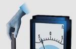
STEPLESS HYDRO TRANSMISSION. In the Elite, the engine from the Volga GAZ-2410 was located in front and actuated the hydraulic pump (Fig. 3). The oil circulated through metal tubes with an inner diameter of 11 mm. There is a dispenser next to the driver, and a receiver in the trunk (Fig. 4). The car does not have a clutch, gearbox, driveshaft, rear axle and differential. Weight savings - almost 200 kg.
In the middle position of the reverse lever, the oil flow is blocked, and it does not enter the driven pumps, so the vehicle does not move. In the “Forward” position of the reverser handle, the oil enters the pump through the dispenser and under pressure, having passed the reverse, into the hydraulic motors. Having done useful work in them,
A hydrostatic transmission is a hydraulic drive with a closed (closed) circuit, which includes one or more hydraulic pumps and motors. The most common application of hydrostatic transmission is the drive of machines on wheels or caterpillars, where the hydraulic drive is designed to transfer mechanical energy from the drive motor to the executive body.
A hydrostatic transmission is a hydraulic drive with a closed (closed) circuit, which includes one or more hydraulic pumps and motors. In Russian and Soviet literature, a different name is used for such hydraulic drives - hydrostatic transmission. The most common application of a hydrostatic transmission is in the propulsion of wheeled or tracked machines - where the hydraulic drive is designed to transfer mechanical power from the drive motor to the axle, wheel or sprocket of the tracked vehicle, by controlling the pump flow and tractive power output by controlling the hydraulic motor.
Hydrostatic transmission has many advantages over mechanical transmission. One of the advantages is the simplification of the mechanical wiring around the machine. This allows you to get a gain in reliability, because often, under a heavy load on the car, the cardans do not withstand and you have to repair the car. In northern conditions, this occurs even more often at low temperatures. By simplifying the mechanical wiring, it is also possible to free up space for auxiliary equipment. The use of a hydrostatic transmission can make it possible to completely remove the shafts and bridges, replacing them with a pumping unit and hydraulic motors with gearboxes built directly into the wheels. Or, in a simpler version, hydraulic motors can be built into the bridge.
The first of the mentioned schemes, where hydraulic motors are built into the wheels, can be applicable for wheeled vehicles, but a variant of such a hydraulic drive for tracked vehicles is more interesting. For such machines, Sauer-Danfoss has also developed a control system based on hydraulic pumps and hydraulic motors of the 90 series, H1 series and 51 series -. Microcontroller control allows for comprehensive control of the machine, starting from diesel engine control. During operation, the system ensures the synchronization of the sides for the rectilinear movement of the machine and the side turn of the machine using the steering wheel or electric joystick.
The second scheme mentioned above is used for tractors or other wheeled vehicles. This is a hydraulic drive, in which there is one hydraulic pump and one hydraulic motor built into the drive axle. To control the hydraulic drive, both mechanical or hydraulic control, as well as the most advanced electrical control technologies using the controller built into the hydraulic pump, can be used. The program for controlling such a hydraulic drive can also be in the MC024 microcontroller installed separately. As well as for “Dual Path”, it allows you to control not only the hydrostatic transmission, but also the engine via the CAN bus. Electric control allows for even smoother and more precise control of the speed of movement and traction power of the machine.
The disadvantage of the hydrostatic transmission can be considered a low efficiency, which is much lower than that of a mechanical transmission. However, compared to mechanical transmissions that include gearboxes, hydrostatic transmission is more economical and faster. This happens due to the fact that at the time of manual gear shifting, you have to release and press the gas pedal. It is at this moment that the engine spends a lot of power, and the speed of the car changes jerkily. All this negatively affects both speed and fuel consumption. In a hydrostatic transmission, this process is smooth and the engine runs more economically, which increases the durability of the entire system.
For hydrostatic transmission, Sauer-Danfoss develops several series of hydraulic pumps and hydraulic motors. The most common in both Russian and foreign technology are adjustable axial piston. Their production began back in the 90s of the last century and now it is a fully debugged line of equipment that has a lot of advantages over the so-called GTS 90, produced by many domestic and foreign companies. The advantages include the compactness of the units, the possibility of making tandem pump units and all control options from mechanical to electro-hydraulic based on the microcontroller control of the PLUS+1 system.
In conjunction with the hydraulic pumps of the 90 series, adjustable axial piston pumps are often used. They may also have different ways of regulating the working volume. Proportional electric control allows you to smoothly adjust the power over the entire range. Discrete electric control allows you to work in low and high power modes, which is used either for various types of soil, or for driving on flat or hilly terrain.
The latest development of Sauer-Danfoss are the H1 series. The principle of their operation is similar to the hydraulic pumps of the 90 series and the motors of the 51 series, respectively. But compared to them, the design was worked out using the latest technology. The number of parts was reduced, which ensures greater reliability, and the dimensions were reduced. But the main difference from the old series can be considered the presence of only one control option - electric. This is a modern trend - to use systems based on complex electronics, controllers. And the H1 series is completely designed for these modern requirements. One of the signs of this is the version of hydraulic pumps with an integrated controller mentioned above.
There are also axial piston hydraulic pumps and hydraulic motors of the 40 and 42 series, which are applicable in low power hydrostatic transmission, where the working volume of the hydraulic pump does not exceed 51 cm 3. Such hydraulic drives can be found in small utility harvesters, skid steer loaders, mowers and other small-sized equipment. Often, gerotor hydraulic motors can be used in such a hydraulic drive. So in Bobcat loaders they are used. For other equipment, gerotor hydraulic motors of the OMT, OMV series are applicable, and for very light equipment.
hydrostatic transmissions
During the first two decades of the automotive industry, a number of hydraulic transmissions were proposed in which fluid under pressure from a pump driven by an engine flows through a hydraulic motor. As a result of movement under the action of the liquid of the working bodies of the hydraulic motor, power is supplied to its shaft. The fluid, of course, carries a certain amount of kinetic energy, however, since it exits the hydraulic motor at the same speed with which it enters it, the amount of kinetic energy does not change and, therefore, does not take part in the transfer of power.
A little later, another type of hydraulic transmission appeared, in which both rotating elements are placed in one crankcase - both the pump wheel, which sets the fluid in motion, and the turbine, into the blades of which the moving fluid hits. In such transmissions, fluid exits the channels between the follower vanes at a much slower absolute speed than it enters, and power is transferred through the fluid in the form of kinetic energy.
Thus, two types of hydraulic transmissions should be distinguished: hydrostatic or volumetric transmissions, in which energy is transferred by fluid pressure acting on moving pistons or blades, and hydrodynamic transmissions, in which energy is transferred by increasing the absolute velocity of the fluid in the pump wheel and reducing the absolute velocity in turbine
The transmission of motion or power by means of fluid pressure has been used with great success in a number of fields. An example of the successful application of such gears are the hydraulic systems of modern machine tools. Other examples are the hydraulic steering mechanisms of ships and the control of the gun turrets of warships. From the point of view of application on automobiles, the most advantageous property of a hydrostatic transmission is the possibility of stepless change in the gear ratio. For this, only a pump is needed, in which the volume described by the pistons in one revolution of the shaft can change smoothly during operation. Another advantage of hydrostatic transmission is the ease of getting reverse gear. In most designs, moving the control beyond the zero speed position and the gear ratio to infinity causes reverse rotation at progressively faster speeds.
The use of oil as a working fluid. In translation, the term "hydraulic" means the use of water as a working fluid. However, in practice, using this term, usually means the use of any fluid for the transmission of motion or power. Mineral oils are used in hydraulic transmissions of all types, as they protect the mechanism from corrosion and at the same time provide lubrication. Low-viscosity oils are usually used, since internal losses increase with increasing viscosity. However, the lower the viscosity, the more difficult it is to prevent leakage of the working fluid.
The use of hydrostatic transmissions in automobiles never left the experimental stage. However, some progress has been made in the use of these transmissions in rail transport. At an exhibition of vehicles in the German city of Seddin, held in the mid-20s, hydraulic transmissions were installed on seven of the eight shunting diesel locomotives on display. These gears are very easy to manage. Since they allow you to get any gear ratio, the engine can always work with the number of revolutions per minute, which corresponds to the highest efficiency.
One of the serious shortcomings that prevent the use of hydrostatic transmissions in automobiles is the dependence of their efficiency on speed. Data have been published in the literature, according to which the maximum efficiency of such transmissions reaches 80%, which is quite acceptable. However, it must be borne in mind that maximum efficiency is always achieved at low operating speeds.
Dependence of efficiency on speed. In hydrostatic transmissions, turbulent fluid flow occurs, and in turbulent motion, losses (heat generation) are directly proportional to the third power of the speed, while the power transmitted by hydrostatic transmission varies in direct proportion to the flow velocity. Therefore, as the flow rate increases, the efficiency drops rapidly. Most of the known data on the efficiency of hydrostatic transmissions relate to rotation speeds well below 1000 rpm (typically 500-700 rpm); if, however, such gears are used to work with an engine whose normal crankshaft rotation speed is over 2000 rpm, then the efficiency will be unacceptably low. Of course, a gear reducer can be installed between the motor and the hydrostatic transmission pump. However, this would make the transmission more complicated by one more unit, and the low-speed pump and hydraulic motor would be unnecessarily heavy. Another disadvantage is the use of high pressures in hydrostatic transmissions, reaching up to 140 kg!cm2, at which, naturally, it is very difficult to prevent leakage of the working fluid. Moreover, all parts subjected to such pressures must be very strong.
Hydrostatic transmissions have not gained popularity in automobiles, not because they have not received enough attention. A number of American and European firms, which had sufficient technical and financial resources, were engaged in the creation of hydrostatic transmissions, in most cases with the intention of using this transmission in automobiles. However, to the best of the author's knowledge, trucks with hydrostatic transmissions never entered production. Where firms have been producing hydrostatic transmissions for some time, they have found a market for them in other industries where high speeds and low weights are not required. Several ingenious hydrostatic transmission designs have been proposed, two of which are described below.
Manly transfer. One of the first automotive hydrostatic transmissions made in the USA is the Manly transmission. It was invented by Charles Manley, an associate of the aeronautical pioneer Langley and chairman of the Society of American Automotive Engineers. The transmission consisted of a five-cylinder variable-stroke radial piston pump and a five-cylinder fixed-stroke radial piston hydraulic motor; The pump was connected to the hydraulic motor by two pipelines. When the direction of rotation was changed, the discharge pipeline became suction, and vice versa; when the pump piston stroke was reduced to zero, the hydraulic motor acted as a brake. To prevent damage to the mechanism from excessive pressure, a safety valve was used, which opened at a pressure of 140 kg/cm2.
A longitudinal section of the Manly transmission is shown in fig. 1. The pump and hydraulic motor were located coaxially next to each other, forming a single compact unit. On the left is a section of one of the pump cylinders. The gap between the piston and the cylinder was very small, and the pistons did not have o-rings. The lower heads of the connecting rods did not cover the crank, but had the shape of sectors and were held by two rings located on both sides of the connecting rod head. The change in the stroke of the pump pistons was carried out using eccentrics mounted on the crankshaft. During the operation of the unit, the crankshaft and eccentrics remained stationary, and the cylinder block rotated around the axis of the eccentrics E. The figure shows the mechanism in a position corresponding to the maximum piston stroke, equal to the sum of the radius of the crank and the eccentricity of its eccentric; the cylinders rotate around the E axis, and the pump pistons around the P axis. To reduce the stroke of the pistons, the eccentric rotates around the E axis in one direction, and the crank rotates around the axis in the opposite direction; thanks to this, the angular position of the crank remains unchanged, and the timing mechanism continues to work as before. Management is carried out with the help of two worm wheels mounted on an eccentric, one of which is planted freely, the second is fixed. The loosely seated worm wheel is connected to the crankshaft by means of a gear mounted on the crankshaft, which engages with internal teeth made on the worm wheel. Worm wheels are engaged with worms connected to each other by two cylindrical gears. Thus, the worms always rotate in opposite directions, and the transmission was designed so that the angular movements of the eccentric and the crank were equal in absolute value and opposite in direction. If the eccentric and the crank were rotated through an angle of 90°, then the stroke of the pump pistons became equal to zero. The timing eccentric was set at 90° to the crank arm. A hydraulic motor differs from a pump only in that it does not have a mechanism for changing the piston stroke. Both the pump and the hydraulic motor have spool valves controlled by eccentrics.

Rice. 1. Hydrostatic transmission Manly:
1 - pump; 2 - hydraulic motor.

Rice. 2. Manly eccentric transmission control.
Manly transmission, intended for use on a 5 g truck with a 24 hp gasoline engine. With. at 1200 rpm, had a pump with cylinders with a diameter of 62.5 mm and a maximum piston stroke of 38 mm. The pump was powered by two hydraulic motors (one for each drive wheel). With a working volume of a five-cylinder pump equal to 604 cm3 for a transmission of 24 liters. With. at 1200 rpm, at the maximum stroke of the pistons, a pressure of 14 kg / cm2 was required. When testing the Manly transmission in the laboratory, it was found that the peak efficiency occurred at 740 rpm of the pump shaft and was 90.9%. With a further increase in the rotation speed, the efficiency dropped sharply and already at 760 rpm was only 81.6%.

Rice. 3. Hydrostatic transmission Jenney.
Transmission by Jenny. The Jenney Transmission has long been built by the Waterbury Tool Company for various industries; in particular, it was also installed on trucks, railcars and diesel locomotives. This transmission consists of a multi-cylinder piston pump with a swash plate and variable stroke and the same hydraulic motor, but with a constant piston stroke. The longitudinal section of the unit is shown in Fig. 144. The difference in the arrangement of a pump and a hydraulic motor lies only in the fact that in the first the tilt of the swash plate can change, but in the second it cannot. The pump and motor shafts protrude from one end each. Each shaft is supported by a plain bearing in the crankcase and a roller bearing in the distributor plate. Attached to the inner end of each shaft is a cylinder block which has nine holes forming cylinders. The axes of these cylinders are parallel to the axis of rotation and are at an equal distance from it. As the cylinder blocks rotate, the cylinder heads slide over the distributor plate. The holes in the head of each cylinder periodically communicate with one of the two windows in the distributor plate, made in an arc of a circle; in this way, the supply and discharge of the working fluid is carried out. The length of each window along the arc is about 125 °, and since the communication of the cylinder with the channel in the plate begins from the moment when the hole in the cylinder head begins to coincide with the window, and continues until the window in the plate is blocked by the edge of the hole, then the opening phase is about 180°.
The springs mounted on the shafts serve to press the cylinder blocks against the distributor plate at a time when the load is not transferred. When transferring a load, contact is provided by fluid pressure. The cylinder blocks are mounted on shafts in such a way that they can slide and wobble slightly on them. This ensures that the cylinder block fits snugly against the distributor plate, even with some manufacturing inaccuracies, as well as in the event of wear.
The clearance between the piston and the cylinder is 0.025 mm and the pistons do not have any sealing devices. Each piston is connected to the swivel ring by means of a connecting rod with spherical heads. The connecting rod body has a longitudinal hole, and a hole is also made in the bottom of each piston. Thus, the connecting rod ends are lubricated with oil from the main fluid flow and the pressure under which the oil is supplied to the bearing surfaces is proportional to the load. Each wobbler is connected to the shafts by cardan joints in such a way that, when it rotates with the shaft, its plane of rotation can make any angle with the axis of the shaft. In the pump, the swash plate angle can be changed from 0 to 20° in any direction. This is achieved by means of a control handle connected to a rotating bearing housing. In the hydraulic motor, the bearing seat is rigidly attached to the crankcase at an angle of 20°.
In cases where the swash plate is at right angles to the shaft, when the cylinder block rotates, the pistons will not move in the cylinders; therefore, there will be no oil supply. But as soon as the angle between the swash plate and the axis of the shaft is changed, the pistons will begin to move in the cylinders. During one half turn, oil is sucked into the cylinder through a hole in the distributor plate; during the second half of the revolution, oil is pumped through the injection port in the distributor plate.
Pressurized oil to the hydraulic motor causes the pistons of the hydraulic motor to move, and forces acting on the swash plate through the connecting rods cause the cylinder block and its shaft to rotate. In the case when the angle of inclination of the swash plate of the pump is equal to the angle of inclination of the swash plate, the hydraulic motor of the latter will rotate at the same speed as the pump shaft; Reducing the rotational speed of the hydraulic motor shaft can be achieved by reducing the angle between the pump swash plate and the shaft.
In a transmission built for a railcar with a 150 hp engine, e., efficiency at 25% load and maximum rotation speed was 65%, and at maximum load - 82%. This type of transmission carries considerable weight; the unit given as an example had a specific gravity of 11.3 kg per 1 liter. With. transmitted power.
TO Category: - Car Clutches