Cars are getting smarter every year - they already independently rotate the steering wheel, change the stiffness of the suspension, give the driver a fifth point massage and much more ... However, the final actuator of most of the car's electrical circuits, a modest "workhorse" is a relay that has practically not changed its design since 1831, when it was first invented ... What is useful for the average car owner to know about the relay?
How the relay is arranged and applied
As you know, the dimensions and power of a switch that switches a powerful load must correspond to this load. It is impossible to turn on such serious current consumers in a car as, say, a radiator fan or glass heating with a tiny button - its contacts will simply burn out from one or two clicks. Accordingly, the button should be large, powerful, tight, with a clear fixation of the on / off positions. It should be connected to long thick wires, designed for the full load current.
But in a modern car with its elegant interior design, there is no place for such buttons, and they try to use thick wires with expensive copper sparingly. Therefore, a relay is most often used as a remote power switch - it is installed next to the load or in a relay box, and we control it using a tiny low-power button with thin wires connected to it, the design of which is easy to fit into the interior of a modern car.
Inside the simplest typical relay there is an electromagnet, to which a weak control signal is applied, and already a movable rocker arm, which attracts the triggered electromagnet, in turn closes two power contacts, which turn on a powerful electrical circuit.
In cars, two types of relays are most often used: with a pair of closing contacts and with a triple of switching ones. In the latter, when the relay is triggered, one contact closes to the common one, and the second one is disconnected from it at this time. There are, of course, more complex relays, with several groups of contacts in one housing - making, breaking, switching. But they are much less common.
Please note that in the picture below, for a relay with a switching contact triple, the working contacts are numbered. The pair of contacts 1 and 2 is called "normally closed". Pair 2 and 3 are "normally open". The “normal” state is the state when the relay coil is NOT energized.

The most common universal automotive relays and their contact outputs with a standard arrangement of legs for installation in a fuse box or in a remote block look like this:
 |
 |

The sealed relay from the non-standard xenon kit looks different. The compound-filled housing allows it to work reliably when installed near headlights, where water and mud mist penetrate under the hood through the grille. The pinout of the outputs is non-standard, so the relay is equipped with its own connector.

For switching high currents, tens and hundreds of amperes, use a relay of a different design than those described above. Technically, the essence is unchanged - the winding attracts a movable core to itself, which closes the contacts, but the contacts have a significant area, the wires are fastened with a bolt from M6 and thicker, the winding is of increased power. Structurally, these relays are similar to the starter solenoid relay. They are used on trucks as mass switches and starting relays of the same starter, on various special equipment to turn on especially powerful consumers. Abnormally, they are used for emergency switching of jeep winches, the creation of air suspension systems, as the main relay for a system of self-made electric vehicles, etc.

 |
 |
By the way, the word “relay” itself is translated from French as “horse harnessing”, and this term appeared in the era of the development of the first telegraph communication lines. The low power of the galvanic batteries of that time did not allow transmitting dots and dashes over long distances - all the electricity "went out" on long wires, and the remaining current that reached the correspondent was unable to move the head of the printing machine. As a result, communication lines began to be made “with interchange stations” - at an intermediate point, not a printing machine was activated by a weakened current, but a weak relay, which, in turn, opened the way for current from a fresh battery - and further, and further ...
What you need to know about the operation of the relay?
Operate voltage
The voltage indicated on the relay housing is the average optimum voltage. “12V” is printed on car relays, but they also work at a voltage of 10 volts, and they will work at 7-8 volts. Similarly, 14.5-14.8 volts, to which the voltage in the on-board network rises when the engine is running, does not harm them. So 12 volts is a nominal value. Although the relay from a 24-volt truck in a 12-volt network will not work - the difference is too great ...

Switching current
The second main parameter of the relay after the operating voltage of the winding is the maximum current that the contact group can pass through itself without overheating and burning. It is usually indicated on the case - in amperes. In principle, the contacts of all automotive relays are quite powerful, there are no “weaklings” here. Even the smallest switches 15-20 amperes, standard-sized relays - 20-40 amperes. If the current is indicated double (for example, 30/40 A), then this means short-term and long-term modes. Actually, the current margin never interferes - but this mainly applies to some kind of non-standard electrical equipment of the car that is connected independently.

Pin numbering
Automotive relay outputs are marked in accordance with the international electrical standard for the automotive industry. The two winding leads are numbered "85" and "86". The conclusions of the contact "two" or "three" (closing or switching) are designated as "30", "87" and "87a".
However, the marking, alas, does not give a guarantee. Russian manufacturers sometimes mark the normally closed contact as "88", and foreign - as "87a". Unexpected variations on the standard numbering are found in unnamed "brands" and companies like Bosch. And sometimes the contacts are even marked with numbers from 1 to 5. So if the type of contacts is not signed on the case, which often happens, it is best to check the pinout of an unknown relay using a tester and a 12 volt power source - more on this below.

Material and type of terminals
The contact outputs of the relay, to which the wiring is connected, can be of the “knife” type (for installing the relay in the socket of the block), as well as for the screw terminal (usually for especially powerful relays or relays of obsolete types). Contacts are "white" or "yellow". Yellow and red are brass and copper, matte whites are tinned copper or brass, shiny whites are nickel-plated steel. Tinned brass and copper do not oxidize, but bare brass and copper are better, although they tend to darken, impairing contact. Nickel-plated steel also does not oxidize, but its resistance is high. It is not bad when the power leads are copper, and the winding leads are nickel-plated steel.

Pluses and minuses of food
In order for the relay to work, a supply voltage is applied to its winding. Its polarity is indifferent to the relay. Plus on "85" and minus on "86", or vice versa - it doesn't matter. One contact of the relay winding, as a rule, is constantly connected to plus or minus, and the second one receives control voltage from a button or some electronic module.
In previous years, a permanent connection of the relay to the minus and a positive control signal were more often used, now the reverse option is more common. Although this is not a dogma - it happens in every way, including within the same car. The only exception to the rule is a relay in which a diode is connected in parallel to the winding - here the polarity is already important.

Relay with diode parallel to coil
If the voltage to the relay winding is supplied not by a button, but by an electronic module (standard or non-standard - for example, security equipment), then when disconnected, the winding gives an inductive voltage surge that can damage the control electronics. To extinguish the surge, a protective diode is switched on in parallel with the relay winding.
As a rule, these diodes are already inside the electronic components, but sometimes (especially in the case of various additional equipment) a relay with a built-in diode is required (in this case, its symbol is marked on the case), and occasionally a remote block is used with a diode soldered on the side of the wires . And if you install some kind of non-standard electrical equipment that, according to the instructions, needs such a relay, you must strictly observe the polarity when connecting the winding.

Case temperature
The relay winding consumes power of about 2-2.5 watts, which is why its case can get quite hot during operation - this is not criminal. But heating is allowed at the winding, and not at the contacts. Overheating of the contacts for the relay is detrimental: they are charred, destroyed and deformed. This happens most often in unsuccessful instances of Russian and Chinese-made relays, in which the contact planes are sometimes not parallel to each other, the contact surface is insufficient due to skew, and during operation there is a point current heating.
The relay does not fail instantly, but sooner or later it stops turning on the load, or vice versa - the contacts are welded to each other, and the relay stops opening. Unfortunately, identifying and preventing such a problem is not entirely realistic.
Relay test
When repairing, a faulty relay is usually temporarily replaced with a serviceable one, and then replaced with a similar one, and that's it. However, you never know what problems may arise, for example, when installing additional equipment. So, it will be useful to know the elementary algorithm for checking the relay in order to diagnose or clarify the pinout - did you suddenly come across a non-standard one? To do this, we need a 12 volt power source (power supply or two wires from the battery) and a tester turned on in resistance measurement mode.
Let's assume that we have a relay with 4 pins - that is, with a pair of normally open contacts that work for closing (a relay with a switching contact "three", is checked in a similar way). First, we touch the probes of the tester in turn to all pairs of contacts. In our case, these are 6 combinations (the image is conditional, purely for understanding).
On one of the combinations of outputs, the ohmmeter should show a resistance of about 80 ohms - this is a winding, remember or mark its contacts (for automotive 12-volt relays of the most common sizes, this resistance ranges from 70 to 120 ohms). We apply a voltage of 12 volts to the winding from the power supply or battery - the relay should clearly click.

Accordingly, the other two outputs should show infinite resistance - these are our normally open working contacts. We connect the tester to them in the dialing mode, and simultaneously apply 12 volts to the winding. The relay clicked, the tester squeaked - everything is in order, the relay is working.

If, on the working terminals, the device suddenly shows a short circuit even without applying voltage to the winding, then we came across a rare relay with NORMALLY CLOSED contacts (opening when voltage is applied to the winding), or, more likely, the overload contacts melted and welded, short-circuiting . In the latter case, the relay is sent to the scrap.
In this article, I will try to highlight the points associated with competent engine blocking, and not from the point of view of the correctness of electrical circuit breaks in the car, but from the point of view of the theft resistance of the locks themselves, that is, let's talk about how to get the most out of an ordinary alarm in terms of locks. But first - the necessary explanations on the topic - for most, the history of the issue may be useful.
So, as you know, modern car alarms have two important functions, for which they, alarms, are actually bought and installed on a variety of cars. Important - meaning - in terms of countering theft, as well as in terms of protection against looting. The first function is directly to notify the owner and others about such attempts, and the second is to prevent, let's say stamped, unauthorized engine start, or, in other words, the start blocking function. Here about it, about blocking, and we will talk in more detail.
It so happened historically that the vast majority of alarms use relays as actuators. This is probably why the motto of hijackers of all times and peoples today sounds like this - “Cherchet la relay”. Blocking relays can be built into the alarm module, or the alarm has special pins on the connector to control such a relay. Or very small, but high-quality and powerful relays are placed in the body of a regular car relay (as you can see in the photo, Fig. 1), Fig. 1 together with a control circuit that carries out switching according to coded commands coming from the signaling unit either via a special wire, or without a wire at all, but via switched circuits in the form of a high-frequency coded signal. It is clear that with the help of such “stuffed” relays, it is possible to organize the most secretive and difficult to neutralize blockages today, because their presence in a car does not give anything away, and hijackers must be highly qualified in order to find such small bugs in a modern car, literally stuffed with various electrical devices and cables. However, alarms that can control wireless relays are much more expensive than the ubiquitous simple systems with ordinary relay interlocks. But if you have the funds - in order to protect your car from theft, preference should be given to such not cheap systems, because the developers with this beautiful solution managed to give installers a fairly effective solution to combat theft - a blocking relay controlled by standard car wiring (or even via radio channel) .
Why? Because the usual standard installed alarm system will not be able to withstand hijackers for more than a few minutes. And the reason lies not only in the standard and predictability of the “mass installation”, but also in the fact that the developers themselves did not pay enough attention at the time to the important function of blocking the engine, even the name for it was invented offensively - “auxiliary”. “Well done”, of course, what do you say - one built-in relay or even just one wire - that’s all that is assigned to them for the implementation of this far from auxiliary, but the same main signaling function, along with notification.
Well, let's see what can be done to correct the situation with "little bloodshed". To “look”, however, you need to have a good idea of what engine blocking algorithms are used in modern car security systems.
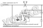
And they - these algorithms - are passive and active. Everything is like in the well-known “minorities” - like relays and relays - but look - it can be “passive”, or maybe “active”. It depends on the algorithm (type, habitat, upbringing - who will become who and what). The active blocking algorithm is the most vulnerable, because the blocking relay, with this algorithm in a de-energized state, allows the engine to start. This type of blocking is otherwise called "normally closed", or simply NC - according to the type of contacts of the blocking relay in the "Protection" mode. A typical scheme for the implementation of NC engine blocking is illustrated in Fig. 2 by a fragment of the connection diagram of a standard Taiwanese signaling - basically NC blocking is used by manufacturers who have narrow eyes from birth. In the "Disarmed" mode, there is no voltage at the blocking output, and hence at the relay winding, and the relay, with its NC contacts (contacts 87a and 30), allows the engine to start. More precisely, it does not prevent it. In the “Protection” state, there is a ground potential on this wire, and when you try to start the engine, a plus from the ignition switch will appear at the second end of the winding, the relay will switch, thus prohibiting the starter from working, in this example.
To neutralize the active blocking, obviously, it is enough to simply de-energize the signaling module in any way. For example, pulling out all the connectors from the module, or simply breaking the wires, and often it is enough to pull the system fuses out of the holders. And that's it - nothing will prevent the engine from starting. This is the main reason - for which I can’t stand blocking NC relay contacts.
With a passive algorithm, the blocking relay prohibits the operation of the engine in a de-energized state, the contacts of such a relay are normally open (the blocking is therefore called NO). This means that in order to unlock the relay, it is necessary to apply voltage to the relay, it will switch, and the engine can be started. On fig. 3 shows an example of a standard fuel pump blocking of an injection engine by an alarm.
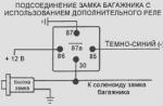
As can be seen from the diagram, the blocking relay breaks the control circuit of the standard fuel pump relay, so the current through its contacts is small, which allows the use of a low-power, and therefore small-sized relay. At the same time, the theft resistance of such a simple blockage is low - it is usually bypassed by applying voltage directly to the gas pump with a jumper. You can slightly improve the quality of blocking by adding another blocking relay (Fig. 4), breaking its contacts with the power wire of the pump. At the same time, it is desirable to partially remove the regular power wire, laying your own wire instead - you get the so-called "spaced" blocking - it will be even more difficult for the rogues to restore the gap. Especially if the second relay is installed directly in the fuel pump hatch, as illustrated in photos 5, 6, 7 and 8.
Rice. 4. The resistor is used in order to make it difficult to diagnose a “malfunction” (specifically, here it is more to illustrate the principle), while diodes are needed so that a short to ground of the lock wire directly at the relay does not turn off the entire lock.

Rice. 5. The photo shows the fuel pump connector and the cable that feeds it. The blocking relay breaks the power wire, and applying voltage using a jumper to the wires in the cabin will not have an effect - it will be necessary to unscrew the fuel pump hatch cover, and it is in our power to use non-standard screws in order to make it more difficult.

Rice. 6. The relay is neatly hidden under the bottom of the trunk, so that after installing the cable in place, the relay would not be visible.

Fig.7. The cable is in place - but where is the relay?

Rice. 8. After screwing the cover back on, it is not easy to guess about the "bug" living under it.
The most important advantage of HP blocking - even if the alarm is de-energized by the above methods - this will not help - to neutralize it is already necessary not only to de-energize the system, but also to connect the blocking output of the alarm to ground. In order to further complicate the task of the hijackers, the developers build a blocking relay inside the alarm module. An example of such a blockage is shown in Figure 9 - the built-in relay breaks the high-current power supply circuit of the gasoline pump - and in order to bypass the blockage, in this case, it is already necessary to restore the gap.
Thus, it is easy to see that HP blocking resists hijackers better - they have to find the right wires in the alarm harness and connect them together. Or find the ground wire on the alarm connector, disconnect it and connect the rest of the wires together. In general, this is already more difficult than pulling the alarm unit out of the connectors. But it's still simple.
Well, it’s clear with HP locks - but what if the alarm has an active NC blocking algorithm with relay contacts. Such questions often arise among those who would like to modify the Taiwanese alarm system at their disposal in order to add protective properties to it “for inexpensive”. There is a way out, but for this it is required to mount a transistor key-inverter in the alarm module. The blocking relay itself is best made remote, and the winding switching circuit is implemented so that 12 volts must be applied to one end of it, and the mass potential to the other. Then twisting all the wires into one pile, or even just two control wires, will not work! The engine will remain blocked.
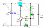
A diagram of such an alteration is shown in Figure 10.

Usually, in standard alarms, the output for NC blocking is taken from the output of the buffer microcircuit (ULN2003A - for example), sometimes, apparently, for "just in case" the developer adds a diode or low-resistance in series - especially if a transistor switch is used instead of a buffer microcircuit, or an output to The lock is taken directly from the processor. A low-resistance resistor or diode acts as a kind of fuse, they must be removed during revision.
In the photo in Figure 11, for example, an alarm board is shown, in which the blocking output is taken directly from the "leg" of the microcircuit (marked with a red arrow) - in this case, you will have to cut the track on the board. The resistance R2 is selected for reasons of optimal current consumption - however, you don’t need to get carried away - after all, the load in the collector circuit of the transistor will be the relay winding, and it depends on the type of relay - what current is needed for the transistor to saturate in the open state, and, accordingly, the resistance value in base. For most cases, composite n-p-n transistors with a load current corresponding to the type of relay are suitable. Naturally, the key converts the blocking algorithm from active NC to passive NR - when the microcircuit is "minus in protection" - the transistor is closed, the relay is de-energized, the engine is blocked. It is advisable to connect the second end of the blocking relay to the “Ignition” wire so that the relay would not be energized when the alarm is turned off for some reason and the engine is not running. However, if the second end of the relay winding is connected to the "Ignition" directly inside the alarm, and even through a diode, as shown in the diagram, then the hijacker's task will become even more complicated - it will no longer be enough to find the wires for blocking and connect them together or to ground - you will need to file a plus on one of them, and a minus on the other, and this is already a 50-50 lottery. At one time, this simple idea was “inspired” by Grigory, aka GrishaTav. This scenario can take place when the hijacker first de-energizes the alarm (and did not succeed), then tries to disconnect the connectors and find a way to block (usually an orange or yellow wire) - again a mistake, then there will certainly be attempts to alternately connect all the "suspicious" wires on mass - time, in a word, all this takes more time. And this is our goal - to maximize the time required for hijacking as much as possible. For this, you can use not one, but several blocking relays connected according to the described algorithm - each such relay will significantly complicate the task of starting the engine for possible hijackers, and, of course, the likelihood for them to be caught at the crime scene will increase. We can work slowly, and our cause is right, and the enemy will be defeated - after all, God himself ordered us to think again and again - what would be done ... good for our car in order to further secure it from theft.

Photo in fig. 12 - illustrates one of the examples of the implementation of this refinement in life - additional elements were successfully placed in place of the soldered light alarm relay (which is soldered and mounted remotely because its characteristic “clicking” contacts during an alarm is an unmasking factor). The blue wire is an additional wire to the other end of the relay winding

As you can see, with properly “sharpened” hands, adding only a transistor and a resistor to the alarm, and a couple of wires is a very simple task - the main thing is to have a good idea of the principle of operation of the described algorithms.
In a similar way, signaling with a passive HP algorithm can be modified with relay contacts - in this case, obviously, a transistor key is not required. And if the developer took care of a more peaceful sleep of the car owner and built a blocking relay inside the alarm module, then you can increase the number of additional remote relays "as your heart desires" - and then the concept of "alarm + immobilizer" in one bottle is obtained - and only at the expense of additional relays and properly-organized interlocks.
Well, well, many will object to me, but after all, it’s necessary to unwind the case, pick up a soldering iron, carefully mount elements, often cut tracks on a printed circuit board - in general, this technology, I agree, is not for everyone. Yes, and with a guarantee for the module, problems are inevitable. A more important point is still this - although after the described improvements it is more difficult, but you can still bypass the blocking relay - they are still tied to the alarm module.
And what if you use not simple, but polarized relays as blocking relays ?! The photographs (Fig. 13 and 14) show several cool copies of such a relay. For comparison, in photo 13 there is also an ordinary automotive relay (on the left) and the radio relay mentioned somewhere at the beginning of the article along with a two-button control panel. Isn't it true - the dimensions of polarized relays are very small. The SDS S2-L-12V relay, which is most pleasant for our purposes, has four contact groups (two NC and two NO) and two stable states. And now about the main advantage of these relays - they switch from one stable state to another only when the polarity of the voltage supplied to the winding changes! This is an interesting property and allows you to organize a unique blocking, approaching in its properties to the coded blocking relays mentioned at the beginning of the article, which are still used mainly in expensive security systems. And most importantly, you can implement the blocking described below for any signaling! In essence, this is a secret, but with control from the main signaling module.


Consider a few typical examples of the use of "little helpers".
Example 1. A polarized relay is connected to power outputs to control door actuators. By the way, I am often asked to draw the most detailed connection diagrams for illustration, with pin numbering, for a specific type of alarm, and in general - to explain everything in as much detail as possible. But in this example, the scheme is so elementary that let me not give it, but limit myself to describing the principle. Namely, when the door locks are closed, the relay is in the “locked” position, when open, it is “locked out”, that is, the winding of the polarized relay is connected simply in parallel to the door activators, because the relay and an ordinary Taiwanese motor are very similar - the same two stable status and switching by changing the polarity of the control pulse. Only the relay is not afraid of constant voltage on the winding, and you cannot switch it by hand from one state to another, like a motor.
It is clear that twisting the wires together here, as in the rest of the examples below, will not allow you to remove the blockage. Intervention in the signaling circuit is not required, the guarantee is preserved. The disadvantage is that without an additional relay, it is impossible to use such a function of many alarms, convenient for some, as closing car door locks while driving. This, I must say, is also a popular topic - how to hang door activators on a low-current alarm output for controlling the central lock, how to organize the connection of additional sensors and a pager transmitter for power, and in our case, how to connect an additional engine blocking, if you want the doors during the movement of the car for safety would be closed by an alarm command? Well, Figure 15 shows a detailed diagram of how this is implemented in practice. At the same time, for an example of “flexibility of thinking”, a more common two-winding relay (RPS28B, RPS34, RPS36, etc.) was taken as a polarized relay - for such types of relays, switching is carried out by applying a control pulse to the corresponding winding, and not by changing the polarity of the control pulse. However, this circumstance does not at all prevent the use of such relays for our purposes.

Figure 15. Using a polarized relay for switching additional actuators and for additional blocking of the engine.
A few notes about the diagram. From the alarm output, the relays that control the door locks receive negative impulses. The polarized two-winding relay is also controlled by the same pulses, so that when the alarm closes the doors, the relay switches to the blocking position (only one group of contacts of the polarized relay is simplified in the diagram, in fact there are usually more of them). When the doors are opened, the lock is also removed. In order to prevent the closing of the doors on the alarm command during movement from blocking the engine, an additional relay is used that breaks the control circuit of the polarized relay along the blocking winding when the ignition is turned on.
Example 2. The alarm has two unused additional channels for controlling external devices - by command from the key fob on the outputs of the additional. channels, negative impulses are formed, switching the polarized relay to the state - “blocked” and “unblocked”. It is this, in general, a rare variant that is shown in the schematic diagram in Fig. 16, with the necessary explanations. Although here it is better to act according to the situation, depending on the capabilities of the security system at your disposal. For example - the alarm has an output for the "Comfort" function, when the windows are additionally closed during arming - OK, we use this impulse to activate the relay - each time the arming is activated, the relay will switch along with the windows up, and our car will receive an additional lock at the cost of in several relays, one of which is very tricky. By the way, to control it, due to the low current consumption (less than 10 milliamps), you can also use the alarm output directly, designed for active blocking.

Does your alarm have an output to remotely open the trunk, or a hood lock, which usually works in the “disarmed” mode - excellent, you can use the output of such a channel to unlock the relay and, accordingly, the engine. At the same time, if you show ingenuity and entrust the responsible task of turning off the relay to the regular buttons of the car or their convenient suitable combination, you will get a lock that is NOT DISABLED from the alarm! The buttons can be very different - there are quite a lot of them in the car - for example, buttons for power windows or mirror controls. It can also be a parking brake limit switch, or a brake pedal limit switch, or a rear speed sensor, or a button for turning on the heated rear window, or a dipped / high beam switch, or a washer button, - finally, a bibical (joke) - but you never know where else you can "get" the necessary "on demand" 12 volts in the interior of the protected car! The options can be very different - it is only important to weed out frankly uncomfortable or those that can be seen from the street - for example, if the ignition is on, then when you press the brake pedal, the stoplights will light up - this can be seen from the outside and figure out how to turn off the "secret toggle switch" in such a car.
But what if the alarm system does not have enough additional channels, and additional manipulations with standard buttons are not desirable (not everyone likes to start the engine of their car every time in “two stomp three crashes”). Such a case is illustrated by the following example (Fig. 17). Here, one end of the relay winding is switched ... by the alarm output to the siren (“the siren”, by the way, can control not only blocking, using this output you can even “teach” the door alarm to open separately, as Yuri Gnatyuk from Arkhangelsk did in his time , aka Jora - he lives here http://jora.by.ru , and here he talked about using the exit to the siren "for other purposes" http://www.auto.ru/wwwboards/stealings/0034/9289.shtml ).

The relay is turned off (in our example) by an additional signaling channel. It turns out an interesting algorithm of work, based on a convenient and useful feature of most alarms, which is difficultly referred to as “silent arming / disarming” or, in other words, without sound confirmation signals by a siren. That is, with a quiet setting, our cunning, really main relay will not activate, and if we also “quietly” disarm the alarm, the relay will “sleep” further. However, any alarm can “wake him up”, or rather, the very first disturbing trill of a siren. The siren, by the way, can work not only in “security”, but also during a robbery attack - and thus a new, unexpected and even “polarized” line of engine protection will appear in front of the robbers - called “try to start”.
Of course, the second, unblocking end of the "cunning" relay can also be connected to the already described combination of standard buttons, which - this is important - will no longer have severe restrictions on the convenience of regular use - because now this will have to be done much less often. For example, when parking in an unfavorable area or for a long time, it is better to put the alarm on "security" with "sound" - it will be calmer. And for a short stop, you can also rely on sensors - which, by definition, are required to provide at least one "crack" of the siren and provide. If during the time that the car was under the protection of the alarm, nothing happened, then the owner of the car turns off the system in the same silent way, sits down and goes about his business. If there was an alarm, then the relay will immediately switch to the “blocked” position, and no manipulations with the alarm will help to switch it back - you will need to use the “two stomp three stomp” method known only to the owner. But this is no longer annoying as in the previous versions, because with correctly adjusted sensors, false alarms rarely occur in alarms. Well, in case of not false alarms, due to the additional line of defense, there is a chance to stay with the car.
So, behind unhurried explanations, we slowly got to the end of the edge of our “savvy”. We throw out the extra relays (which also need to be shunted with diodes “just in case” - and this takes time during installation, which is money, extra connections appear that reduce reliability, etc.), and there remains such a simple “obscenely” the schematic in Fig. 18 is an original solution, isn't it?! The characteristics of "cunning" relays allow them to do well without their ordinary "clattering" contacts of their counterparts. One end is connected to ground through the resistance of a conventional non-autonomous siren (a fuse (or diode) connected in series with the siren protects the alarm output to the siren - because now this output has the important task of activating the "sleeping" lock). The second end "sits on ground" through an additional penny resistance of 100 ohms, since the resistance of the relay winding is kilo-ohm or more. How the scheme works is elementary, dear Watson. The relay is activated by any siren signals - including service ones, this has already been described. And it turns off - with a reed switch, through the contacts of which 12 volts are supplied to the second winding of the relay at the moment we need. He held the reed switch with a magnet in the right place on the skin, while the siren quietly “says” like this - everything is in order, the relay is turned off, and boldly start the engine. The reed switch can also be taken with switching contacts - they are just less common, but the usual NC reed switch (it is NC when paired with a magnet, and without a magnetic mate, its state is normally open as in the diagram) and a resistor are sold everywhere. Where to hide the reed switch in the car is not a problem - they are so small that you can choose and hide anywhere - up to the “bibika”, and this is no longer a joke.

Thus, the use of such relays - relatively cheap, but very suitable for, I'm not afraid of this word - the sacred task of worthy blocking OUR car - a serious bid for victory in the fight against hijackers - after all, a ghost lock, so you can call it - does not turn off, even if the entire signaling subject is found, and, at the same time, it practically does not bother in everyday use. The reliability of the relay, of course, is higher than that of complex microprocessor devices, and this makes it absolutely unnecessary, in order to exclude warranty claims, to provide for “emergency” bypasses of locks - it’s no secret that car owners, if something happens to the engine, first of all sin to the alarm. And of course, in such cases, they often don’t remember what they were shown on the service to disable the blocking. And in the case of using polarized relays, the user himself turns them off periodically, and this circuit can only fail due to poor installation, which in itself is nonsense - it’s the same as it’s bad to fasten the mass of the alarm. Particularly pleasing is the fact that polarized relays are much smaller in size than such serious competitors as Hook-Up relays, which allows them to be wound directly into bundles, making the task of detecting them difficult in practice.
Why are there harnesses - for those who have the right hands and who love original non-standard solutions - the last illustration (Fig. 19) in this article is a blocking relay placed in the body of a conventional autonomous siren. The calculation is simple - a valuable thing is most often the most difficult to find if it lies in a conspicuous place. The hijacker will first of all “spoil” the siren that is painfully familiar to everyone, cut off the wires to it, and thereby further complicate the task of starting the engine. Does it ever occur to anyone that the relay can live in the body of a standard siren? But she is both warm and dry there - except that it is loud at times. Let's hope she's deaf from birth.

And the hijackers will only have the opportunity to try themselves in the field of “bypassing” these little bugs, but we will talk about how to prevent them specifically and not expensively, I hope, in the next article.
Annex 1.A brief overview of domestic standard relays in cases as shown in the photo below.
The information of one manufacturer will be given below, there are other manufacturers and foreign analogues. For this part of the article, the main thing is to make it clear to an ordinary motorist that relays can be interchangeable, have different circuits, a different number of contacts, depending on the purpose.
Domestic relays of this series mark the normally closed contact as 88. In imported relays, this contact is everywhere called 87a
Typical relay circuits. Sokolevka.
 Scheme 1 |
 Scheme 1a |
According to scheme 1, the following 5-pin (switching) relays are produced:
With 12V control - 90.3747, 75.3777, 75.3777-01, 75.3777-02, 75.3777-40, 75.3777-41, 75.3777-42
With 24V control - 901.3747, 901.3747-11, 905.3747, 751.3777, 751.3777-01, 751.3777-02, 751.3777-40, 751.3777-41, 751.3777-42
According to scheme 1a with an anti-interference resistor:
With 12V control - 902.3747, 906.3747, 752.101, 752.3777, 752.3777-01, 752.3777-02, 752.3777-40, 752.3777-41, 752.3777-42
With 24V control - 903.3747, 903.3747-01, 907.3747, 753.3777, 753.3777-01, 753.3777-02, 753.3777-40, 753.3777-41, 753.3777-42
 Scheme 2 |
 Scheme 2a |
According to scheme 2, the following 4-pin (closing / closing) relays are produced:
With 12V control - 90.3747-10, 75.3777-10, 75.3777-11, 75.3777-12, 75.3777-50, 75.3777-51, 75.3777-52, 754.3777, 754.3777-01, 754.3 777-02, 754.3777-10, 754.3777-11, 754.3777-12, 754.3777-20, 754.3777-21, 754.3777-22, 754.3777-30, 754.3777-31, 754.3777-32
With 24V control - 904.3747-10, 90.3747-11, 901.3747-11, 905.3747-10, 751.3777-10, 751.3777-11, 751.3777-12, 751.3777-50, 751.3777- 51, 751.3777-52, 755.3777, 755.3777-01, 755.3777-02 755.3777-10 755.3777-11 755.3777-12 755.3777-20 755.3777-21 755.3777-22 755.3777-30 755.3777-31 3777-32
According to scheme 2a with an anti-interference resistor:
With 12V control - 902.3747-10, 906.3747-10
With 24V control - 902.3747-11, 903.3747-11, 907.3747-10
 Scheme 3 |
 Scheme 3a |
According to scheme 3, the following 4-pin (NC / OFF) relays are produced:
With 12V control - 90-3747-20, 904-3747-20, 90-3747-21, 75.3777-20, 75.3777-202, 75.3777-21, 75.3777-22, 75.3777-60, 75.3777-602, 7 5.3777-61, 75.3777-62
With 24V control - 901-3747-21, 905-3747-20, 751.3777-20, 751.3777-202, 751.3777-21, 751.3777-22, 751.3777-60, 751.3777-602, 751.37 77-61, 751.3777-62
According to scheme 3a with an anti-interference resistor:
With 12V control - 902-3747-20, 906-3747-20, 902-3747-21, 752.3777-20, 752.3777-21, 752.3777-22, 751.3777-60, 751.3777-61, 751.3777 -62,
With 24V control - 903-3747-21, 907-3747-20, 753.3777-20, 753.3777-21, 753.3777-22, 753.3777-60, 753.3777-61, 753.3777-62,
ATTENTION!!!
Relays of the 19.3777 series have a housing similar to the above. The circuit of these relays has a protective and decoupling diodes. Such relays have a polar winding. Here in the article, these relays are not mentioned, since they have limited application.
Relays of modern cars.

Differences and diversity of relay numbers means different fastenings, housing design, degree of protection, coil control voltage, switched currents and other parameters. Sometimes when choosing an analogue, it is necessary to take into account some parameters.
According to scheme 5, the following 4-pin (closing / closing) relays are produced:
With 12V control - 98.3747-10, 982.3747-10
With 24V control - 981.3747-10, 983.3747-10
According to scheme 5a with an anti-interference resistor:
With 12V control - 98.3747-11, 98.3747-111, 982.3747-11
With 24V control - 981.3747-11, 983.3747-11
The next thing he hits is engine blocking.
Before continuing our detective story, we will have to figure out in general terms what to block, how to block, and in general, what kind of animal this is, blocking. Useful for understanding further developments. It turned out long, but with pictures.
The locks must be designed in such a way as to fundamentally exclude the possibility of bypassing them without lifting the hood, which in turn should be as difficult as possible. This is the cornerstone. Then there will be a bit of boring stuff, sorry, without it in any way.
Necessary educational program
For clarity, I drew a picture that is slightly higher.
A modern engine runs under the control of a foreman, which is a computer called an ECU (Electronic Control Unit, popularly “brains”). At the input, the readings of various sensors (top left), at the output of the command to open injectors in specific cylinders and ignite the mixture (top right).
To start the engine, it is necessary to recognize the ignition key, which is done by a separate module, without a command from which the ECU will not allow the engine to start. This is just the same as the hijacker.
Finally, the ECU gives the go-ahead to turn on the fuel pump, starter, and also supplies voltage to many places.
There is also a CAN bus, but we will sing this song separately.
When you put the key in the ignition and turn it, what happens? That's right, the lights on the dash light up. But a little earlier, the ECU manages to interrogate the key, understand that it is its own, allow the engine to start, turn on the fuel pump. And then the lights turn on. After the starter is turned on, the ECU goes into the mode of polling the sensors and issuing orders for the injection and ignition of the fuel.
Physically, this goodness is a bunch of wires spreading from the “brains” throughout the engine compartment. They are not very visible, since the wires are neatly bundled and hidden away from the owner's crooked hands so as not to accidentally damage them.
As you understand, if any wire is cut, the engine most likely will not work. You can check. If you cut a wire and the engine is still running, try another one. A broken wire is obviously a malfunction. A serviceman can fix the problem, you can also check it by bringing the car on a tow truck. A normal serviceman will quickly understand what the problem is and find a broken wire, and he will not go through all the wires in a row. This is also an important point, remember it.
What is blocking
Blocking is an artificially created malfunction, without the elimination of which the engine cannot work.
Obviously, if, for example, the fuel pump is turned off, the fuel will stop flowing into the engine, and it will not work. You can disable the ignition circuit or injectors (which inject fuel), the result will be the same.
Disconnect should be understood literally - cut the wire.
The essence of blocking is just this, a certain electrical circuit is physically broken, a button is placed in the place of the break, which the driver must hold pressed while driving. Released the button - the car stalled. Joke. But the essence is exactly this, only instead of a button a relay is used that can break and close the circuit, thus creating and eliminating a malfunction by an external command issued by an alarm unit or other device.
Locks can be divided into several types by execution and into several types by connection. Both have a significant impact on theft resistance, so I took out the consideration of locks in a separate post, more precisely, even in two posts.
The terminology is in places my own, since no established classification exists.
Types of blocking by execution
First, the simplest analog.
First option simplest. The blocking relay is located directly in the alarm unit.

The broken circuit is connected directly to the block.
Advantages. Ease of implementation, fault tolerance.
Flaws. It is not protection against theft, since having reached the alarm unit (a), you can easily restore a broken electrical circuit.
Second option is a development of the first. The blocking relay is taken out of the alarm unit and hidden under the hood. The control is carried out by a wire connecting the relay to the alarm by simply applying voltage. For example, there is voltage - we close the circuit, there is no voltage - we open it.

Advantages. Fault tolerance. The resistance is slightly higher than the first option.
Flaws. It is not protection against theft, since having reached the alarm unit (a), you can easily apply voltage to the control wire, thereby restoring the broken electrical circuit.
Digital locks
Third option- development of the second. Physically, everything looks exactly the same, but to unlock via the control wire, you need to give a certain digital signal, a kind of password. Simply applying voltage will not help. And nothing will help at all, except for the correct password.
Advantages. Fault tolerance. Doesn't lend itself to quick hacking.
Flaws. The presence of a cable from the alarm unit to the blocking relay allows you to find the relay through this cable and disable the blocking.
Summary. The ability to find the relay by cable gives rise to the requirement to carefully hide this cable so that it is impossible to quickly find the relay, which will make the search attempt pointless. Connection has the right to life.
Fourth option differs from all previous ones in the absence of a direct physical connection between the alarm unit and the blocking relay. The control signal is supplied through the vehicle's standard wiring. The signal itself is digital, of course.

Advantages
Flaws. A hijacker can apply digital "noise" to the wiring, thereby preventing the transmission of a control signal.
Summary. The connection has the right to life, provided that the situation is provided for the supply of “noise” to the electrical network of the car without reducing theft resistance. In addition, a highly skilled installer is required for reliable operation.
Here the question may arise: well, the hijacker gave “noise”, well, the relay did not see the control signal, so what? Blocking will not close the circuit, and this is exactly what is required! Not always. There are situations when blocking is disabled by default, but only works if certain conditions are met. More on that later.
Fifth option. The control signal is transmitted over a radio channel. The signal is digital, of course.

Advantages. Inability to detect blockage by wires. Doesn't lend itself to quick hacking.
Flaws. The hijacker can turn on the radio noisemaker, which will interfere with receiving the control signal. Problems can also arise during everyday use in conditions of strong radio noise. The installer, together with the owner, must foresee all this so that dangerous situations do not arise.
Summary. The connection has the right to life, provided that problems during operation are excluded and it is impossible to bypass the blocking with a noise maker.
Summary
Locks must be digital, that is, the last three types. Only they are not opened by simple methods. Obviously, when the broken circuit is under the hood, and the blocking relay is located there, it is impossible in principle to eliminate it without raising the hood.
This also implies the complete senselessness of placing locks in the car, as is almost always done when installing security at official dealers. Usually also next to the alarm unit. The lock can be very smart, with complex password encryption algorithms and so on, but when there is physical access to it, it does not matter, the hijacker will simply close the broken circuit. He does not even need to think what kind of circuit is broken, there is no need, when the blocking relay is here, taped to the alarm unit with electrical tape.
I take this opportunity to emphasize once again that , no less than the quality of the system itself. Similarly, it is very important during operation.
However, when installing and configuring, it is absolutely necessary to take into account the nuances of operation in order to avoid unpleasant situations when the rightful owner cannot use his own car. And vice versa, when the interference put by the hijacker allows you to bypass the blockage - there should be no other way around, except to raise the hood and restore the broken circuit.
Let's consider an equally important issue, what can be blocked to make it difficult to start the engine.