The engine block relay is an anti-theft device that allows you to remotely block the engine and perform control. Its use, along with car alarms, makes a whole anti-theft complex out of the “signaling”.
[ Hide ]
Functions and working principle
Depending on the manufacturer, the manufacturing technology and operation of the security system may be different. The principle of operation is to break the electrical circuit of the starter device when an unauthorized start of movement is attempted. The transmission of encrypted pulses from the blocker or the processor module of the anti-theft complex can be performed in several ways. This is done through standard electrical circuits, via a separate radio channel or via radio transmission.
In digital type devices, a standard electrical circuit is used to transmit packet data. The wire has a special analog channel, which allows for an increased speed of information transfer. Packet data is actually collected around the perimeter of the vehicle. Before sending information to the consumer's console, the anti-theft complex performs code diagnostics for legitimacy. The data can be transmitted to the consumer's communicator or mobile gadget, depending on the capabilities of the "signaling".
The essence of the blocker lies in the physical break of one of the power lines, and the control button is installed at the place of the break. This key is clamped at the beginning of the movement, which ensures the start of the power unit. If the button is released when trying to start the internal combustion engine, then this will not work. By means of a key, a signal is given to the alarm relay to open or close the contacts.
Andrey Kondrashov spoke about the principle of operation of the internal combustion engine blocking relays.
The blocking module of the power unit can operate in remote or automatic mode. If you have configured the first option, then the motor control of the machine can be performed from a distance. Such devices are usually more advanced and can be controlled using a communicator from a signaling device or a mobile device.
If automatic mode is preferable, then the consumer can independently set the time for blocking the power unit by timer. The setting of this option can be performed according to the temperature in the passenger compartment of the car, the specified time interval or the temperature of the internal combustion engine.
Design
The radio relay is made in a small block, the body of the device is usually made of plastic. Structurally, the block itself includes an electronic circuit, as well as a relay chip. These components are used to monitor specific controllers installed in the machine.
The automatic blocking module itself includes a set of electrical circuits. They are used to connect via the CAN bus or to the standard wiring of the machine. If the car is equipped with an "alarm" with auto start, then a relay must also be connected to this system. The small size of the housing allows you to install the blocker of the power unit anywhere in the car. When choosing the installation location of the relay, it is necessary to take into account the location of the points through which it will be connected to the standard electrical wiring of the car.
Block relay design
Kinds
On sale you can find several types of internal combustion engine blockers. We will analyze the features of each of them in more detail.
Ordinary
Conventional analog devices can be made in several variations. The first option is considered the simplest in execution, it is installed in the microprocessor-based car alarm module. The broken electrical circuit is connected to the control module. The main advantage of such blockers is ease of installation and high fault tolerance. But these devices cannot be classified as anti-theft devices. If the criminal gets to the microprocessor unit, he will be able to quickly restore the broken circuit.
There are more advanced analog relays. Such blockers are removed from the signaling microprocessor module and installed in the engine compartment. The control procedure is carried out via an electric line that connects the relay to the anti-theft complex by means of a conventional voltage supply. If voltage is supplied to the blocker, then the circuit closes; when it is absent, the contacts of the element are open.
The advantages of such devices include fault tolerance. Compared to the first option, the theft resistance in remote blockers is higher, but it also cannot be attributed to full-fledged anti-theft agents. If the criminal gains access to the microprocessor device, he can quickly apply voltage to the control power line. This will restore the broken circuit and start the engine.
Analog engine blocking relays are not recommended for use, since they cannot provide effective protection against theft.
Channel Nördlich Bär showed the principle of operation of a simple blocker of the power unit.
Digital
Digital devices are divided into several types:
- Simple digital lock. A more advanced version of the above option, visually looks similar, only for unlocking a digital pulse is transmitted through the control power line. In fact, it is a password, just voltage cannot be used to unlock it. Such blockers are not subject to quick hacking, which makes them more reliable and fault-tolerant. The disadvantages include the presence of a wire from the microprocessor module going to the blocking relay, this will allow an attacker to determine the location of the relay. To prevent theft, the electrical circuit itself must be hidden with high quality.
- Blocker without direct connection with the microprocessor module. The transmission of control pulses is carried out through the standard electrical circuits of the machine, the signal is made in the form of digital packet data. The advantages include the difficulty of detecting a device by electrical circuits; in practice, such blockers are not amenable to quick hacking. But a criminal can, using special devices, interfere with regular electrical circuits, this will lead to the fact that the signal does not go to the relay and the blocking will not be performed. The installation of such blockers is advisable if there is resistance to signaling noise; installation will require the help of a qualified specialist.
- The next type of devices is digital with the transmission of control pulses via radio channels. It is impossible to determine such a blocker in a car by power lines; these devices are less susceptible to hacking. But a professional criminal will be able to use the same “noise maker”, which contributes to the formation of interference and the impossibility of transmitting control impulses. In areas where strong radio noise prevails, operational difficulties may arise, especially in large cities. When installing, the car owner must take into account all these points. It is important to make sure that the criminal cannot bypass the device using a noise maker.
According to the technical parameters, digital devices are divided among themselves:
- By size. The device can be with relay imitation, made in a miniature housing for hidden installation. On sale you can find hermetic blockers designed for installation outside the car.
- The magnitude of the switched current. Depending on the device, the blocker can be rated for 5-40 amperes.
- The type of transmission and reception of signals. Digital devices can operate via electrical circuits, from the signal of the on-board network, via a special radio channel from the main module. More advanced devices can work with transponder keys.
- By the length of the transmitted signal and the type of transmission. Packet data by constant code is transmitted over 4-8 bit channels. When using dynamic locking, the code length will be from 16 to 100 bits. The length of the dialog code can be any, this option is considered the most reliable and safe.
- If possible, protection against detection by "dialing".
Digital device with direct connection to the block Blocker without direct connection to the processor unit Digital device with a radio channel for data transmission
Wireless
Such interlocks cannot be forced to open or close contacts by applying voltage. An electronic board is installed in the device case, which is controlled by an electromechanical component. The transmission of commands is encrypted, so it is almost impossible to detect the signal and intercept it.
The main advantage of wireless blockers is that the consumer can simultaneously install several dozens of such devices on the car's motor, it all depends on financial capabilities.
Single wire
Single-wire devices are not affected by interference. To connect such blockers, not a regular electrical circuit is used, but a separate single-wire line, packet data is transmitted through it. This type of connection allows you to provide reliable protection against interference, increased loads, as well as increase the power of the transmitted pulse. The wiring does not transmit code signals, so if a criminal wants to use a bug to break into, he will have to find the appropriate cable.
The disadvantages of the devices include the complexity of installation compared to wireless blockers. To prevent the relay from being turned off by intruders, it can be moved to the engine compartment and an additional lock can be installed on the hood. Single-wire relays are not so in demand among consumers. The fact is that it is almost impossible to implement an invisible lock with a wire.
The channel "WUST-TV - All about GPS monitoring" spoke about the installation of a GPS tracker, as well as a blocking relay on the example of a tractor.
How to connect and set up?
You can install and connect the blocking device yourself.
Relay with self-locking
Let's analyze an example of connecting the "signaling" blocker Starline B62 Dialog. On the main board of the microprocessor unit there is a blocking device with a group of switching contact elements. On Starline B62, this output is marked as X1. The maximum generated current is 15 amperes.
The connection procedure is as follows:
- Before installation, programming of a specific mode of operation of the relay is carried out. Depending on the signaling model, the setup process may differ. In the case of the B62 Dialog system, programmable option 10 is used for configuration. Initially, the device is set to normally closed interlock.
- Decide on a mounting location. The installation must be performed in one of the regular electrical circuits for blocking the power unit. For example, you can install the device in the gap of the fuel pump or injectors.
- Two of the three contact elements of the built-in blocker are connected to the formed gap. Blue and white-blue wires are used for connection. These electrical circuits are included in the "signaling" package.
- If the connection is made in a power line break with an inductive load, the magnitude of the current must be taken into account. The maximum switching parameter may be greater than the maximum current with which the blocker operates. This may cause it to break.
Relay with remote blocking
We will analyze an example of a safe connection of a digital relay using the Starline P2 model as an example. A detailed connection diagram of the device is presented in the technical manual.
Before you install and connect the blocking relay, you need to deal with one of the operating modes of the device. It is determined by the consumer according to the state of the electrical circuit loop that comes out of the blocker board. If the loop is intact, then closed mode is activated, open - normally open.
Connection and installation:
- The installation procedure is the same. The device crashes into one of the electrical circuits of the machine - the fuel pump, injectors or starter device.
- To connect, you need to go to the settings menu of the main options of the "signaling". Select the blocker operation mode - 3 or 4 options 10, you can learn more about the functions from the service manual. Once selected, turn off the option setting menu.
- Connect the black cable marked MAC to the car body.
- Turn off the ignition and click on the Valet service button seven times.
- Turn the key in the lock to turn on the ignition. The signaling siren will emit seven beeps, this indicates entering the blocker setting mode.
- Within five seconds, connect the black cable marked FLIGHT to the ignition system power line. If the device is paired, the siren speaker will play one long beep.
- To leave the binding mode, turn off the ignition system or wait five seconds and the “signaling” will automatically leave the menu. If you plan to use several relays, then the second device is installed and connected in the same way. When the second relay is successfully bound, the siren will emit two extended beeps.
If, in the event of an attempt to bind the blocker, the siren played three extended signals, this indicates that the device has already been entered into the memory of the microprocessor unit.
A blocker that has been saved to memory cannot be linked to another communicator, for this you will have to reset all settings.
Andrey Kondrashov spoke about the independent implementation of car engine blocking.
How to choose a relay?
When buying a device, you must take into account the main selection criteria and manufacturers.
Criterias of choice
Nuances to consider when buying:
- The type of device to be used. The type of blocker is determined in accordance with the needs of the car owner.
- Overall dimensions of the device. To make the installation discreet and difficult to detect, give preference to blockers made in a small case.
- Decide on the place of installation. If the installation is carried out in the cabin, then any type of device will do. If you plan to install the relay in the engine compartment or under the bottom of the car, then buy blockers made in a sealed housing. They will prevent the negative impact of external factors on the operation of the device.
- Manufacturer. The more famous the manufacturer, the more likely it is that their product will last a long time.
- Technical parameters of the car. Blockers can work with currents of different sizes. This nuance must be taken into account before buying in order to prevent the relay from failing under increased load.
- The type of signal to use for control. Dialog encoding is considered the most efficient.
- Additional features. If the manufacturer claims that its product is protected from interference and scanners, we recommend that you read consumer reviews on the Web about this model.
An overview of the selection options, as well as the Starline R2 relay, is shown on the AutoAudioCenter video.
Manufacturers and models
The most popular models of blockers:
- Pandora VM-105. A wireless device designed for installation in vehicles with a 12-volt on-board network. Installation of the blocker on trucks and buses that use a 24-volt electrical network is not allowed. The device uses the block principle of signal encryption, and the key length for data transmission is 64 bits. The blocker is compatible with many Pandora signaling models. The cost of the device is 3000 rubles.
- Starline R4. The device, made in a small case, is designed for flush mounting in a bundle with standard car wiring. The module is equipped with all the necessary elements that will provide control of the hood lock and hidden blocking of the power unit. The control procedure is performed via a single-wire digital line. If the car is equipped with an anti-theft system, before buying it is necessary to clarify the possibility of connecting the blocker to a specific signaling model. Since the device is controlled via one line, the consumer does not need to pull additional wires into the cabin. The code lock provides the ability to control the hood limit switch, as well as the activation of the ignition system. The cost of the device is 2200 rubles.
- Sobr Standard. The device of domestic production, is characterized by the presence of normally closed contacts. The amount of current with which the blocker works is 10 amperes. A dynamic communication channel is used for control. The device is made in a small-sized case, which ensures ease of installation anywhere in the cabin. To detect the blocker, the criminal will have to check all the cables in the car. In case of an unauthorized attempt to start the engine, the contact elements are unlocked, which leads to blocking of the internal combustion engine. The price of the device is 2950 rubles.
- Pandect IS-125. The device was developed by the manufacturer AlarmTrade specifically for use in cars equipped with “signals”. The blocker is also compatible with other anti-theft systems and new immobilizers. The device is mounted in the engine compartment, the blocker is connected to the microprocessor module via a radio signal. Dialogue encoding is used for data transmission, all information is transmitted in the range from 2.4 to 2.5 GHz. The device is protected against short circuits and is energy efficient. The cost of the device is 3300 rubles.
Schemes of simple blocking and more complicated.
Some are made with slight modifications, this is not to say that I am repeating myself, but just trying to anticipate the childish questions of self-installation.
All these circuits are controlled with the ignition on!
If for someone this is not new or simple, then you can not read it.
The first scheme is a classic relay application for self-locking or self-locking blocking.
It implies blocking the simplest ignition circuit.
To control the blocking relay, you can use a secret button, a pair of reed switches and a magnet.

The second scheme almost completely repeats the first. It either has a regular control that issues a positive polarity control signal when the ignition is on (for example, a power signal on the power window or rear window heating). Using this circuit, you can control from the radio wire to the active antenna. The only inconvenience is that the radio should always be in good working order, and the removable panel should not be forgotten at home.

The third scheme is another of the clones of the first two. The first relay in the diagram operates on the principle of self-locking and controls the second relay, which performs the main function of blocking the engine of any circuit independent of ignition. Here you can also use standard or other controls (in particular, the radio), but you need to add another diode, as in the second diagram.

This schematic is similar to the ones above. This is ground signal control and therefore two relays are required. If there is a desire and an opportunity to use a regular button, then you will need a decoupling diode in the button circuit.

The circuit is taken from the 12volt website. Original starter lock controlled by horn. The condition is the same as for foreign cars, when the ignition is off, the horn does not work. When using this scheme, after turning on the ignition, the horn does not work. After clicking on the signal, you can start. After the start, the beep starts to work. Possible control options from other bodies of the car. The right upper and lower relays can be small.

This simplest scheme allows you to make an additional blocking (secret) of the engine using a displacement / acceleration sensor, on a system with a remote start.
The Star Line B9 alarm system was chosen for installation. The blocking is activated automatically from the signaling channel immediately after the ignition is turned off or when arming. Activation after turning off the ignition is convenient because this signal cannot be scanned or blocked via radio broadcast. Thus, the engine can be started, but after the start of movement it will stall.
Disabling the lock was used from the standard button, but with the ignition off. There is some inconvenience in this. If the engine is started from the auto starter, then before starting the movement it is necessary to turn it off or if the engine stalls for any reason, then after turning off the ignition, it is also necessary to press the unlock button. Here you have to sacrifice either convenience or the security properties of the complex. Disabling the lock can be done with a separate secret button or a pair of reed switches-magnet.
The ignition circuit to the engine control unit was blocked. With a short-term signal from the sensor, the engine stalled and the dashboard lit up, and it could be started right away and everything was repeated at the beginning of the movement. Other circuits may be blocked.

This circuit also uses a motion sensor or a shock sensor.
Proposed by Ultra Star technical specialist - Mikhail Chausov.
This circuit uses the principle of relay self-blocking (as in the first circuits of this article), but the sensor output to control the engine blocking itself is blocked.
In general, it repeats the previous scheme with the difference in the use of conventional and polarized relays.

I developed this circuit for cars in which, after turning off the ignition, power remains on the coil (coils) for some time. For example, for the operation of a turbo timer. Its meaning is that after the ignition is turned off, the blocking does not yet occur. The engine is blocked after the turbo timer is stopped or the power is turned off at the consumer, and a blockage occurs if an attempt is made to restart the ignition with the key itself. I have not had to test it on a car, but assembled on a table, it works. The circuit uses 1N4001 - 1N4007 diodes and a 1000uF capacitor. Perhaps the diode D3 and the capacitor will not be needed in real conditions.
Next, six schemes from Vladimir (nickname ded99).
I publish them without his permission, and if there are complaints, I will immediately remove the schemes from the site.
I did not have to use these schemes.
The text with comments is also from my namesake Vladimir.

QUASI-SIGNALING.
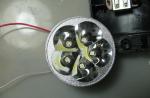
When the ignition is off, the LED starts flashing, simulating the operation of a car alarm. When the ignition is on, the LED goes out without distracting the driver.

BLOCKING WITH THE HELP OF A CAPACITOR.
When the toggle switch S is turned on, an additional capacitor C bl is connected in parallel with the spark-extinguishing capacitor Spr, which shunts the breaker contacts and reduces the power of the spark energy in the ignition system: “there is a spark, but it does not start”. It is almost impossible to detect an additional connection using the dialing method.
Disadvantage of blocking: burning of breaker contacts if the client forgot to turn off the blocking.

RESISTOR BLOCKING
When the toggle switch S is turned on, an additional resistor (8 ... 12 Ohm) is connected in parallel with the contacts of the breaker, which reduces the power of the spark energy in the ignition system: "there is a spark, but it does not start."
Disadvantage of blocking: resistor heating (10 ... 15 W) if the ignition is left on for a long time (in case of unsuccessful hijacking), a heat sink of the resistor is required.

LOCK BY TIMER
When the toggle switch S is on and when the ignition is turned on, the capacitor C1 (10 μF) is charged through the resistor R1 (0.5 ... 1.0 MΩ). 5 ... 10 seconds after the ignition is turned on, the key on the transistor VT1 opens and the relay is activated, opening (closing) the vital circuits of the ignition system.

ENGINE LOCK WHEN DRIVING
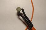
With the help of a motion sensor, pulses from the tachometer are selected, which are accumulated either by the counter or by the integrator and turn on the executive relay. As a sensitive element of the sensor, a coil of a small-sized relay (for example, RES15) without a housing is used. The coil is installed next to the speedometer cable near its attachment to the instrument cluster (end to the rear wall of the unit). Resistor R1 (0.1 ... 1 kOhm) determines the sensitivity of the sensor.

LOCKING WITHOUT TOGGLE
If the ignition is turned on unauthorized, the Kbl relay will turn on with the help of a timer in 5 ... 10 seconds (time constant R3C2), which will block the ignition. To ensure the normal operation of the engine, it is necessary to press the appropriate limit switch, such as a handbrake or brake, with the ignition on. In this case, the timer will be blocked and the ignition will not turn off. When the ignition is turned off for a short time, the timer is blocked by the storage capacitor C1. When the ignition is turned off for a long time, the circuit automatically returns to the blocking mode.
Disadvantage: when the ignition is on, it is possible to bypass the blockage by sorting through all the limit switches.
The scheme below was developed in collaboration with my colleague Valery Kiselev back in 1999. Since then I have improved it a bit. Here is a diagram of the old version. The new version is protected from disconnection by a large magnet, there is also a more secure version where the place for the magnet is point.

In armed mode, the device blocks the engine with normally open contacts of the remote relay.
The armed mode is indicated by a lit or blinking LED.
To unlock the engine, it is enough to hold the magnet at the device installation site at a distance of no more than two centimeters, while the LED will turn off and the engine will be unlocked for a period of 25 to 40 seconds; if the ignition is not turned on during this time, the engine will be blocked automatically. After turning off the ignition, the lock also turns on automatically after 25 - 40 seconds.
Technical data
It is recommended to install under the plastic panels in a place convenient for unlocking on the driver's side. Fastens under the panel on a double-fix.
The convenience lies in the fact that you can mount the lock without removing the panels, in fairly narrow places. If the LED is not set, the blocking does not give itself away.
| Designation | Denomination | Quantity (piece) | Note |
| resistance | |||
| R1, R2 | 20 kOhm | 2 | 18 - 22 kOhm |
| R3 | 150 ohm | 1 | |
| R4 | 20 kOhm | 1 | 18 - 22 kOhm |
| R5 | 10 kOhm | 1 | |
| R6 | 20 kOhm | 1 | 18 - 22 kOhm |
| R7 | 330 kOhm | 1 | 300 kOhm |
| R8 | 20 kOhm | 1 | 18 - 22 kOhm |
| R9 | 1 kOhm | 1 | |
| R10,R11 | 20 kOhm | 2 | 18 - 22 kOhm |
| R12 | 10 kOhm | 1 | 8.2 - 10 kOhm |
| Capacitors | |||
| C1,C2 | 0.1uF | 2 | 0.068 - 0.33uF |
| C3,C4 | 100uF | 2 | K50-35(imp) 16V |
| Diodes | |||
| D1,D2 | 1N4005 | 2 | |
| D3 | BZX84C12SMD | 1 | Sabilitron 12V |
| D4 | 1N4005 | 1 | |
| transistors | |||
| VT1, VT2 | BC847 | 2 | |
| VT3 | KT829 | 1 | |
| Chip | |||
| A1 | CD4011 | 1 | |
| Reed switch G | MK10 - 3 | 1 | |
A few conclusions on the last scheme:
In fact, for a large number of different cars, the installation did not become fast. The choice of installation location should be convenient for the driver and there should be no metal objects nearby. Otherwise, the range of the magnet is reduced. A number of improvements have been made. The device became impossible to remove with a large magnet.
The next diagram is similar to the previous one.
I just removed everything related to the indication of the mode in which the lock is located. And the reed switch itself, or just to say the wires, took it out of the board. The board has become smaller, and the reed switch in the case can now be installed in narrower places. And the indication remains - the very fact the engine starts or not.

Now you can use a remote external button instead of a reed switch. Or use the stock button. But back to the reed switch. A remark was made to me a very long time ago that by moving a large magnet around the interior of a car, you can accidentally turn off the lock. Yes, it is, although of course it's funny to see a car thief with a big magnet shamanizing in the car. And yet, if you connect a couple more reed switches to the wire that is connected to the resistor R3, and connect the second wire of additional reed switches to ground. Next, place additional reed switches around the main one, then it will be possible to turn it off with a large magnet if you drive very slowly along the installation site, and even in a certain direction.
How to use regular buttons to control the lock.
Actually, not all and not always possible to use regular buttons. It is clear that they enable or disable any consumers and functions in the car. But they all work, as a rule, with the ignition on (except for turning on the dimensions, but this button / switch will not work for us). The rest of the time, basically on all the wires of the button, you can see the ground signal and nothing happens when switching. So, we need to determine which contacts close or open on the button. Next, I usually assemble the following circuit from two small relays.

Two additional small-sized relays, when the ignition is off, disconnect the button from the standard wiring, and this button can be used to control the lock.
Another point to increase secrecy is to increase the value of the resistor R3 to 5.7 kOhm. In this case, to unlock it will be necessary not only to quickly press the button or bring the magnet to the reed switch, it will be necessary to hold the pressed button or magnet for a little more than a second.
The next scheme was born from the first version.

The algorithm of work is similar. The difference is that the input contact G must be shorted to ground. Moreover, if this contact remains connected to ground but the ignition is turned off, the system will turn on the lock as expected in about 40 seconds. And to unlock it, you must first disconnect the contact from the mass and again apply mass to it. The control can be a button, a regular button, a reed switch with any state of contacts. If you use the standard button as described above, then you will need one additional relay to turn it off.
Engine blocking in the system Pandora can be done in three ways:
- Using one of the relays built into the base unit (for blocking any circuit, with a maximum current of not more than 9A). Factory setting CH10.
- Using one of the relays built into the base unit to organize the ignition block (no more than 9A). To do this, it is necessary to connect the ignition to the gap and select the ignition connection option, item II-8.5 of the programming menu, accordingly.
- Using conventional automotive external relays controlled by timer channels (CH1-CH12) and programming them to control the blocking relay
- With the help of code relays, controlled by a dynamic code on one wire. Connection to a timer channel (CH1-CH12) is possible (factory setting is CH4).
By increasing the number of locks and applying various methods of organizing the lock, it is possible to achieve a very high anti-theft resistance of the system. It is recommended to organize at least two locks with different work logic.
Connection of blocking code relays.
For the highest level of anti-theft resistance, use the BM-103/105 1-wire BM-103/105 rolling code relay (sold separately).

The advantages of this blocking method are that even if the base unit of the system is detected, the hidden relay cannot be turned on by simply applying power or shorting the wire to ground. The relay has small overall dimensions and can be disguised in a wiring harness.
The relay is connected as follows:
- Strip the ends of the wires coming out of the relay.
- Connect one of the "Black" wires coming out of the relay to the output of the timer channel (by default - CH4), connect the second to the wire of the car's standard wiring, where "+ 12V" appears when the ignition is on, the polarity of the "Black" wires of the relay is not important. It is necessary to make sure that the power supply does not disappear on the “+ 12V” wire selected for connection while driving.
NOTE: in the modified BM-103d relay, the wire connected to “+12V” is red. - Break the blocking circuit of the car, connect two "Grey" wires from the blocking relay (blocking HP) into the gap.
- Close the "Green" wire "Learning", coming out of the relay: to the output of the timer channel (by default - CH4) for VM-103; to ground - for VM-105
- In the "disarmed" mode, turn on the ignition twice with a pause of at least 2 seconds. When the ignition is switched on for the second time, if the training was successful, the relay should turn on. If it does not turn on, then turn off and turn on the ignition again.
- Switch off the ignition.
- Disconnect the "Green" wire and insulate it securely. Turn on the ignition - the relay should turn on.
- Mask the relay in the wiring harness with electrical tape.
Most often, locks are installed on the following car circuits:
- ignition circuits;
- starter circuits;
- electrical circuits of the fuel pump;
- engine sensor circuits;
- injector circuits;
- fuel pump, by installing an additional electromechanical valve (not included).
It must be remembered that locks that are highly resistant to hacking can only be obtained using a non-standard approach.
It should be borne in mind that the method of blocking should not create problems while the car is moving and reduce controllability. If this requirement is not observed, in case of emergency situations, the manufacturer is not responsible.
To power the blocking code relays, you should choose such car circuits in which + 12V voltage does not disappear during movement, even temporarily.
The ability to reliably block the start of the engine in the event of an alarm for signaling is necessary. Another thing is that blocking the motor competently is not so easy: by modern standards, it is considered necessary that the hijacker spend at least half an hour bypassing the protective circuits. Therefore, it is not for nothing that it is said that the alarm installer must think like a hijacker: when setting the alarm, he asks himself the first question “how can they turn it off or bypass it?”.
An auto electrician-diagnostician, a certified StarLine specialist, works on the site. If you have questions about car alarms, ask them at the end of the article in the comments or Vkontakte.
Relay interlocks
The engine blocking relay is the simplest and most common way to prevent unauthorized starting of the motor. Regardless of whether the relay is built into the central alarm unit itself or an external one is installed, the essence of its operation is the same. As long as no current flows in its winding (cars use relays with low-current windings, so they can be directly connected to the alarm output channels), the relay armature (common contact, 30) is electrically connected to a normally closed contact (NC, 88 or 87a). But, as soon as the current is applied to the winding, the relay core becomes magnetized and attracts the armature to itself. The normally closed contact is disconnected from the common contact, which is connected to the normally open contact (HP, 87).

Any relay blocking scheme is selected:
1. When the engine is blocked by a normally closed contact, the relay closes the protected circuit, opening it only when an alarm is triggered. This is convenient because the relay does not wear out with such a connection; in high-current circuits, its contacts do not burn. But as soon as the hijacker disconnects the control wire or disconnects the central alarm unit from the connectors, he will not even have to look for this relay: it will remain closed forever.
2. When blocking by a normally open contact, each time the ignition is turned on on a disarmed car, the contacts close, opening when the ignition is turned off. The relay wears out, but when the central alarm unit is turned off, the protected circuit will remain open. Therefore, this method is more reliable. Please note that in most alarms, the blocking relay output is initially programmed for NC blocking, and NO only works after changing the settings.

Which circuits can be reliably protected with a relay interlock? The most useless thing is the starter blocking relay, because on many cars the starter is turned on forcibly by closing the contacts of the solenoid relay under the hood with a screwdriver or wrench. In addition, such a blocking is useless during a robbery: by taking away an already running car from you, the robber will be able to safely leave.
Proper blocking of the engine should prevent the engine from working. For a modern injection engine, the blocking points are:
1. Fuel pump power circuit
A simple and convenient blocking, but useless on cars with easy access to the fuel pump hatch: the hijacker will not even look for a relay, but simply connect a small battery directly to the fuel pump connector.

2. Blocking the power circuits of the ignition coils or injectors
It will also not allow you to start the engine, but if you have access to the engine compartment, it will cost in the same way, with a temporary wire. Without a reliable additional hood lock, such a lock will not stop a thief for a long time.
3. Blockage of the crankshaft position sensor circuit
The most effective - if the controller does not receive information about the rotation of the crankshaft, neither the injectors nor the ignition coils will receive pulses from the injection ECU. The hijacker will be able to “catch” this blockage only with the help of a diagnostic scanner - an open circuit in the DPKV circuit will be recorded in the computer memory. To avoid this error, we connect the relay a little trickier:

The resistance of the resistor R1 must be equal to the resistance of the winding of the crankshaft position sensor. In this case, when the blocking relay is activated, a "trick" is connected to the inputs of the injection computer, and instead of fixing the error, the computer will not "see" the rotation of the crankshaft.
The blocking relay switching diagrams indicate a diode connected in parallel with the winding. In some relays, it is even built in initially. What is it for? The fact is that the relay winding has a certain inductance, and when the power is turned off, a sharp surge of voltage occurs in it with a polarity opposite to the original one. Therefore, the diode, turned on “vice versa”, without affecting the normal operation of the relay, opens at the moment of such a surge, protecting the low-current alarm output.
Something else useful for you:
Relay with concealed control
The disadvantage of relay blocking is obvious - you have to pull the control wire from the central unit to the connection point, and it needs to be hidden in regular harnesses. Having found this wire, the hijacker will be able to trace both the location of the relay and the location of the central alarm unit.
To avoid this, complex electronic relays are used, controlled both by radio channel (as in StarLine alarms), and by code pulses via standard wiring. Consider the operation of the StarLine R2 blocking radio relay.

This device is compact so that it can even be woven into the wiring harnesses themselves, and has been supported by StarLine alarms for a long time. To communicate with the central alarm unit, the same dialogue code is used as for controlling the alarm itself; it is impossible to force an activated relay to turn off using tools like code grabbers.
The relay can switch current up to 10 amperes, it is possible to use both normally closed and normally open circuits. In the latter case, open the case and cut the wire loop on the board.

After connecting the relay to the blocked circuit (no more than two R2 relays can be used), it is registered in the memory of the central unit. For this:
- with the ignition off, you need to press the alarm Valet button 7 times;
- turn on the ignition and wait until 7 short siren signals sound;
- connect the power wire of the prescribed radio relay to the circuit, where there is always +12 V. The relay will be registered in the memory of the central unit, after which the siren will emit 1 signal;
- if you connect a second relay, power it in the same way. After pairing with the central unit, 2 siren sounds will sound;
- turn off the ignition;
- disconnect power from the alarm central unit for at least 10 seconds.
Remember that when performing the procedure for re-registration of key fobs, it is necessary to repeat the re-registration of installed radio relays.
Starting from the 4th generation of StarLine alarms (A94/A64, B94/B64, D94/D64, E91/E61, E90/E60, A93/A63 and beyond, which have the letter "S" in the serial number of the central unit - for example, B94SW405618988) , it became possible to use a more modern relay R4. It has an increased current load, and a special control mode for the hood electric lock has appeared. In this way, you can connect an electric lock without pulling power wires from it into the passenger compartment, and from the point of view of car security, this is much more effective. At the same time, two locks are implemented in StarLine R4 - through the built-in key according to the NO or NC circuit and through an external relay according to the NC circuit.

However, you will need to connect the INPUT output to one of the additional channels of the alarm central unit. At the same time, it is configured to work with a code relay. For example, the following channels are used on StarLine B94/D94 alarms:

The control function of the selected channel is set to 3. Next, to register the code relay, it is connected to power and ground, after which:
- Connect the INPUT and OUTPUT wires together without disconnecting the INPUT from the auxiliary channel.
- With the ignition off, press the Valet button 7 times.
- Turn on the ignition and immediately turn it off.
- When the relay is written into the unit's memory, the hood lock will automatically close and open.
Blocking via CAN bus
However, on modern cars there is an even more elegant way to block the engine from starting. At the same time, there are no physically broken circuits, just as there are no additional connections: it is enough for the alarm to have a connection with the car's CAN bus.
The essence of such a blocking is that when an alarm is triggered, the alarm sends a blocking command via the bus and repeats it all the time until the alarm is turned off. And until the hijacker turns off the central unit, attempts to start the engine will be useless. If we take into account that with a competent installation of the central unit, to remove it, you will need to disassemble half of the cabin, then this method is clearly the leader in terms of efficiency. At the same time, there is no reason to be afraid of reliability: the blocking relay can break, the contacts can oxidize, and this blocking is exclusively virtual and appears only when necessary.
How to find out if your car can be blocked via the CAN bus? For StarLine systems, just go to can.starline.ru and select your car model to get the available list of CAN functions for it. In it, we are interested in "Engine blocking" and "Prohibition of starting the engine" - in the first case, the checkmark opposite means that the alarm is capable of turning off the running engine, in the second - preventing it from starting.
The engine blocking relay is an integral part of any anti-theft system. With its help, the vehicle is protected from theft by intruders.
Relay features
ATTENTION! Found a completely simple way to reduce fuel consumption! Don't believe? An auto mechanic with 15 years of experience also did not believe until he tried it. And now he saves 35,000 rubles a year on gasoline!
The operation of the engine block relay is carried out along with other functions and car alarm systems. The encrypted signal from the immobilizer or the central car alarm unit can be transmitted in three different ways. It can be transmitted by standard wiring, a separate dedicated channel or radio transmission.
The most common is the use of digital relays, which use standard wiring for data transmission. The wiring is characterized by the presence of an analog channel, which ensures a high signal transmission rate. Its passage is carried out almost along the entire perimeter of the vehicle. When sending a signal by a car alarm, the code is checked for legitimacy, as well as  signal transmission to the owner of the vehicle on the phone or equipment key fob.
Features of the alarm
Almost all modern car alarms are characterized by the presence of shock or tilt sensors. During the period of their operation, the relay blocks the engine, which makes it impossible to move on the vehicle. The device can be activated remotely. This function can be activated promptly for one trip only. Disabling the device from armed mode is performed in two steps, which guarantees the most reliable protection. If necessary, connect a personal code, which will significantly enhance security.
In the cabin, the light is delayed for several minutes after the device is set to armed mode. The alarm system is a universal security system with which you can fully protect the car from intruders. The equipment is characterized by simple design, which makes it easy to install. With this equipment, the trunk can be opened from a distance. Full-fledged work of the security complex is carried out at a temperature of -40-+85 degrees, which allows it to be used in harsh climatic conditions.
The main unit of the device is small in size, which allows it to be installed in any place of the vehicle convenient for the car owner. It is quite simple to execute it. Initially, it is necessary to connect all the wiring in accordance with the diagram. After that, the equipment is configured. Due to the presence of power outputs to the car locks, the doors can be locked or unlocked at the request of the vehicle owner. With the help of the special Valet mode, all security functions can be turned off as soon as possible.
The equipment is equipped with an immobilizer, which provides it with excellent anti-theft qualities. In order to limit vehicle theft, the fuel supply may be cut off, the transmission switched off, or an electrical circuit opened. If there is a need for an emergency shutdown, then a person can use a personal pin code. Also, two additional channels can be programmed on the device. Convenience during the use of the equipment is provided with the help of additional power outputs for locks and turn signals. With this equipment, certain channels can be set remotely. The equipment is a universal security complex, which guarantees a high level of vehicle security.
Advanced alarm options
The equipment is equipped with a special mode, which determines the presence of two-way communication. In emergency situations, it bypasses faulty zones, which ensures long and uninterrupted operation. A device with auto start can check the temperature inside the car from a distance. Thanks to the silent guard mode, the most convenient control of the car alarm is guaranteed.
The security functions in the equipment are performed automatically, which guarantees convenient use of the device. It is possible to install security sensors on five independent zones. When operating the equipment, the user receives sound alerts, with the help of which his actions are confirmed. The instruction manual gives information that when using this equipment, two key fobs can be controlled simultaneously.
Due to the presence of an electronic protection system in the equipment, the possibility of software hacking is excluded. When using a key fob, any of its buttons can be blocked. It also provides the ability to simultaneously block all buttons. The immobilizer is an effective anti-theft system. It only takes one button to control it. When you try to steal a function car, it is immobilized.
The car alarm can shut off the fuel supply, open an electrical circuit, or disable the transmission. Signaling can be instantaneous or after a certain time has elapsed. Locking and unlocking the doors at the request of the car owner can be carried out due to the presence of power outputs to the locks.
Equipment design
 The engine lock relay system is characterized by a fairly simple design. This is a small box made from plastic. It is a block with which the automatic blocking of the motor is activated at a distance. The unit consists of an electronic board and relay microcircuits that control certain vehicle sensors.
The automatic blocking module also consists of a set of wires. With their help, the standard electrical wiring of the vehicle and the autorun system are connected. Due to the small dimensions of this device, its installation can be carried out in any convenient place in the car. The location of the box should be characterized by the presence of points through which it will be connected to the standard wiring of the vehicle.
The operation of the automatic blocking of the motor can be carried out using one of two modes: remote or automatic. When using the automatic mode, you can set the engine blocking time using a timer. Its programming can be carried out according to the temperature in the cabin, the set time, the engine temperature. Remote control of the vehicle engines is carried out by the car owner at a distance. For this purpose, both a mobile phone and a car alarm key fob can be used.
The block of autoblocking can be connected according to two schemes. In the first case, an autonomous connection is made along with a car alarm. Such a connection scheme is used if the vehicle is characterized by the absence of a security system. In this case, the device can be connected to cars with turbocharged or atmospheric, diesel or gasoline. The operation of such a module can be carried out with an automatic or manual transmission.
Installation of auto-lock can be carried out by a master without relevant experience due to its simplicity  this procedure. For this purpose, an automatic blocking module is used, as well as an immobilizer crawler unit. You can also use a car alarm that has this function. If you need to install an auto-lock system, you can seek help from specialists.
Removing the system from the auto-lock function
A distinctive feature of the autostart circuit for diesel engines is the additional connection of the glow plug control circuit. In this case, when the automatic start block enters the security complex, the car alarm blocking is automatically turned off, and then the ignition and starter are activated. When the autostart unit is installed autonomously, the immobilizer is initially cared for, and after that the module supplies power to the ignition and starter circuits.
Bypassing the standard immobilizer is a rather important operation during the installation of the automatic start module. This is due to the fact that one of the functions of the anti-theft system is to break the electrical circuit (or several of them). This affects the start of the vehicle's engine. That is why during the installation period, a block is installed that has a digital microcircuit. With its help, conflicts are eliminated between such units as an anti-theft device and autorun. In most cases, this unit is a spare ignition key. An immobilizer deactivation chip is installed in it.

Regardless of whether the automatic start system has an automatic or remote control principle, it is characterized by an identical operation scheme. At the set time or when commands are received from the remote control or from a mobile phone, electric current is supplied to the ignition circuit from the automatic start module. After that, within two seconds, the oil pressure level in the line is restored. At the next stage of equipment operation, the starter is turned on.
Almost all security systems are equipped with an automatic engine blocking system. With their help, the possibility of car theft is limited.