The site is in test mode. We apologize for errors and inaccuracies.
We ask you to write to us about inaccuracies and problems through the feedback form.
Charging attachments for rechargeable batteries 6F22.
To power small-sized electronic equipment, Ni-Cd and Ni-MH batteries of AA and AAA sizes are widely used today. Less common are batteries used instead of galvanic voltages of 9 V (“Krona”, “Korund”): domestic Ni-Cd “Nika”, 7D-0.125 and foreign Ni-MH size 6F22 from different manufacturers (the same size includes batteries GP17R8H, GP17R9H and others from GP). The capacity of these batteries is 0.1 ... 0.25 Ah, the nominal voltage is 8.4 ... 9.6 V, and their charging requires specialized chargers, which are extremely rare on sale rather expensive universal devices). The article below describes two attachments that allow you to charge nine-volt batteries from an existing power source. The charger for a stabilized power supply with an output voltage of 12 V is assembled on three transistors (2 x KT315B, KT361B), the charger for a cell phone, which is an adjustable boost voltage converter, is based on three KT342AM transistors and a K561LN2 chip. Drawings of printed circuit boards of both attachments are given. .

About five years ago, I purchased a Nikon Coolpix L320 camera, which runs on four AA batteries / accumulators. At first I used only alkaline batteries, but they were enough for a couple of dozen shots, and then the camera refused to work, so in order to save money and stable operation, I decided to buy high-quality Fujitsu 2000 mAh HR-3UTC EX Ni-Mh batteries without memory effect with LSD technology (low self-discharge) and high current efficiency, ideal for flash charging.
To charge the batteries, at first I used the ATABA AT-308 charger, which was bought a very long time ago, but the quality of the charger did not suit me.

The charge principle was reduced to limiting the charging current from the transformer power source by means of current-limiting resistors, in addition, the declared charge current of 150 mA did not correspond to reality and was much less, the same situation was when charging 6F22 (“Krona”), the charge current was less than 10 mA.


It was decided to make our own charger in the ATABA AT-308 case, but with a different concept, which would include battery charge control and visual control of the end of the charge
Materials:
chip LM324;
chip MC34063;
TL431 chip (adjustable precision zener diode);
chip LM317;
transistor KT815 (NPN transistor);
LEDs 5 pcs;
resistor 0.5 ohm;
resistor 10 Ohm 2W;
resistor 27 ohm;
resistor 39-51 Ohm;
180 ohm resistor;
470 ohm resistor;
750 ohm resistor;
resistor 1 kΩ;
resistor 2 kΩ;
resistor 3 kΩ;
resistor 8.2 kOhm;
resistor 10 kΩ;
resistor 36 kΩ;
diode 1N4007;
Schottky diode 1N5819;
throttle;
non-polar capacitor 0.1 uF;
non-polar capacitor 470 pF;
oxide capacitor 100 uF;
oxide capacitor 470 uF.
Tools:
soldering iron, solder, flux;
electric drill;
jigsaw;
drill.
Step-by-step instructions for making a charger for Ni-Cd and Ni-Mh batteries
The heart of the charger is the LM324 microcircuit, in the case of which there are four independent operational amplifiers.

The circuit is designed to charge one battery, so I will assemble a four-channel device on the LM324 chip, while the R5-R6-R7-R8-TL431 chain will be common to all channels. The inverted inputs of the LM324 are combined and connected to R5. The output voltage (on the batteries when charging) is set to 1.46 V using an adjustable precision zener diode TL431 and resistors R6 and R7.
The charge current is set by resistor R3 and at a value of 5 ohms, is about 260 mA, which slightly exceeds 0.1C for my case. Reducing the value of R3 will increase the charge current proportionally. To obtain the required current, I connected two 10 ohm resistors in parallel (there was no required rating). The power of the resistors is 2W.
It is possible to replace the KT815 transistor with a complete foreign analogue BD135 or another one, choosing according to the characteristics. I got 2 pcs. KT815, KT817 and BD135
The end of the battery charge is signaled by the LED. As the charge progresses, the LED will dim until it fades out at the end of the charge. LEDs put superbright 5 mm.
In addition, the ATABA AT-308 charger assumed charging 2 pcs of 6F22 batteries (“Krona”), and since I use one of these to power the multimeter, I decided to create a simple circuit for charging with a current of 25-30 mA in parallel.

The first part of the circuit is based on the MC34063 chip, which will convert the 5V from the power supply that I will be using for my charger to 10.5-11V. This is the simplest solution in my case, especially with limited space for mounting radio components.
To obtain the required output voltage, it is necessary to select the voltage divider resistors. The network is full of online calculators for this chip, if you do not want to manually recalculate.
The second part of the circuit is assembled on an integrated linear voltage regulator, and in my case - current, LM317L with an output current of up to 100 mA. The stabilizer assembled according to this scheme performs the function of current stabilization, which is important when charging the battery. The charging current is adjusted by selecting the resistor R6, the calculation of which can be viewed in the datasheet on the microcircuit or calculated on an online calculator. I set myself 51 Ohm for a charge current of 25 mA. LED HL1 and resistor R5 act as a node for indicating the charging process.
Since the circuit had to fit in the ATABA AT-308 case, the printed circuit board had to be separated taking into account the "features" of the case, namely, the battery contact pads, mounting holes and indicator LEDs had to remain in their places.

I drew the printed circuit board in the SprintLayout_6.0 program.

I transferred the image to the foil textolite using the LUT method, etched it, drilled holes on the printed circuit board and tinned the printed current-carrying tracks with tin-lead solder. Well, as usual, there is nothing to tell.

I soldered the radio components on the printed circuit board in accordance with the circuit diagram. Resistors R3 raised above the PCB to improve thermal conditions.


The case of the former ATABA AT-308 was slightly altered, cutting off the mains plug and patching up the hole with a plastic insert.

I made a short USB cable to connect the charger to the power supply. I use the power supply with the characteristics of 5V 2.5A, which is obtained with a margin for the charger.
To power small-sized electronic equipment, Ni-Cd and Ni-MH batteries of AA and AAA sizes are widely used today. Less common are batteries used instead of galvanic voltages of 9 V ("Krona", "Korund"): domestic Ni-Cd "Nika", 7D-0.125 and foreign Ni-MH size 6F22 from different manufacturers (the same size includes batteries GP17R8H, GP17R9H and others from GP). The capacity of these batteries is 0.1 ... 0.25 Ah, the nominal voltage is 8.4 ... 9.6 V, and their charging requires specialized chargers, which are extremely rare on sale (usually the ability to charge such batteries available only in rather expensive universal devices). The article below describes two attachments that allow you to charge nine-volt batteries from an existing power source.
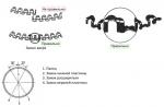
You can make your own charger (charger) for batteries of size 6F22 based on a rectifier with a quenching capacitor, but due to the galvanic connection with the network, it can be unsafe to operate. A charger with a step-down transformer is safe, but, firstly, there may not be a suitable transformer either at home or in a store, and you will have to wind it yourself, and secondly, the dimensions of such a device will be larger. A possible way out is to make a charging attachment to an existing source, for example, to a laboratory power supply with an output voltage of 12 V or to a charger from a cell phone (5 V). The diagram of the charging attachment to a stabilized power supply with an output voltage of 12 V is shown in fig. 1.

The charging current of the battery battery connected to connector X1 is set with a trimming resistor R8. Transistors VT1, VT2 and resistors R4 - R7 form a charging current control unit. The VD1 diode prevents the battery from discharging through the set-top box and the power source if the latter is disconnected from the network or the voltage is lost in it. After connecting to the set-top box, a current I charge1 flows through the battery being charged, determined by its own voltage UB, the power supply voltage Upit by the resistance of the resistor R3 and the inserted part R8 (the effect of shunting resistors R6 and R7 can be ignored) and, finally, the voltage drop UVD1 on the diode VD1: I charge1 \u003d (U pet - U B - U VD1) / (R3 + R8). When the battery is discharged to 7 V, this current does not exceed 2.5 mA, so the voltage drop across the resistor R8 is not enough to open the transistors VT1, VT2, the HL1 LED does not light and the VT3 transistor is closed. When you press the SB1 ("Start") button, the transistor VT3 opens, and the charging current increases to the value I charge2 = (U pit - U B - U VD1 - U VT3) / R8, where U VT3 is the voltage drop in the emitter-collector section transistor VT3. In this case, the voltage on the engine of the tuning resistor R6 increases so much that the transistor VT1 opens, therefore, after the button is released, both of these transistors remain open and the battery starts charging with a current of 15 ... 50 mA (depending on the input resistance of the tuned resistor R8).
LED HL1 indicates the progress of the process. As the battery is charged, the voltage of the battery rises, and the charging current and the voltage drop across resistor R8 decrease. When the battery voltage reaches approximately 10.5 V, the transistor VT1, followed by VT3, closes, the HL1 LED goes out and the battery charging (stops. From that moment on, only a small current I charge3 (about 1 mA) flows through it, determined mainly resistance of resistor R3. If due to a battery malfunction or a short circuit of the output of the set-top box, the current in the charging circuit exceeds 50 ... 60 mA, transistor VT2 will open, transistors VT1, VT3 will start to close and as a result, the output current will be limited. shown in Fig. 2.

This device is an adjustable voltage boost converter. On inverters DD1.1-DD1.3, a master pulse generator with a repetition rate of about 30 kHz is assembled, and on DD1.4-DD1.6 and transistor VT1, a control pulse shaper for transistor VT2, which operates in the key mode. The impulse voltage generated on its collector is rectified by the VD1 diode, the capacitors C6, C7 are smoothing. After connecting to the X1 connector, the battery starts charging through the HL2 LED (it lights up) and the R7 resistor. If the charging current turns out to be more than 20 ... .25 mA, the voltage drop across this resistor will open the transistor VT1, it will bypass the resistor R4 and the duration of the control pulses will decrease, therefore, the rectified voltage and charging current will decrease. This ensures its stabilization during the charging process. When the battery is discharged, the transistor VT3 is closed and the HL1 LED does not light. As it charges, the current through the serial circuit VD2R9 increases, the voltage drop across the trimmer resistor R9 increases and there comes a moment when the transistor VT3 starts to open. As a result, part of the rectifier output current begins to flow through this transistor and the HL1 LED, and the charging current decreases. In other words, the brightness of the HL1 LED gradually increases, and the HL2 LED decreases. The latter continues to glow faintly even after charging is completed, since the current of the VD2 zener diode and a small (about 1 mA) charging current flows through it, which is safe for the battery (it can remain connected to the set-top box for an unlimited time). The printed circuit board drawing of the first attachment is shown on rice. 3, and the second one in Fig. 4.


All parts are mounted on them, except for the connectors for connecting the battery and power source. Fixed resistors - P1 -4, C2-23, tuning resistors - SPZ-19a, oxide capacitors - imported (for example, the Jamicon TK series), the rest - K10-17. Transistors of the n-p-n structure can be of the KT342, KT3102 series, and p-n-p - of the KT3107 series. LEDs - any with a direct voltage of 1.8 ... 2.5 V and a maximum allowable current of up to 25 mA. Possible replacement of the diode 1N5819 (see Fig. 1) - D310, D311, diode KD522B (see Fig. 2) - KD521A, 1N5819, zener diode KS162A - KS175A, KS182A. Choke L1 (see Fig. 2) - DM-0.2, button SB1 (see Fig. 1) - PKN-159. If the output current limiting mode in the first attachment is not needed, the elements VT2, R5, R7 are not installed. To connect a rechargeable battery to attachments, two-pin connectors are used (similar to the pads used in batteries of this type), which exclude incorrect connection, and to connect to a power source and a cell phone charger, the corresponding connectors are used. The author used a charger with an output voltage of 5 V, which is equipped with a USB-A socket. To dock with it, the charger was equipped with a cable with a USB-A plug, which made it possible to charge the battery from a computer. The appearance of the mounted attachments is shown in fig. 5 and 6.

Set up the first prefix in this sequence. Having set the sliders of the trimming resistors R6 - R8 to the lower (according to the diagram) position, connect a discharged battery to the X1 connector and a milliammeter connected in series with it with a measurement limit of 100 mA. The power supply is turned on and, by pressing the SB1 button, the maximum (initial) charging current is set with the resistor R8 (no more than 50 ... 60 mA). Then the battery is replaced with a constant resistor with a resistance of 100 ohms and, by moving the slider of the resistor R7, the current is increased by 10 mA in relation to the previously set one. Next, a freshly charged battery is connected (without a milliammeter) and, slowly turning the trimmer resistor R6, the HL1 LED goes out. After that, several control charging cycles are carried out and, if necessary, adjustment is repeated.

The second prefix is adjusted as follows. By setting the slider of the resistor R9 to the lower (according to the diagram) position, the capacitor C5 is temporarily closed with a wire jumper. Then, as in setting up the first set-top box, a discharged battery and a milliammeter connected in series are connected to the output. Turning on the power supply, with a tuned resistor R2, a current is set in the charging circuit that exceeds the desired charging current by 10 ... 20%. After removing the jumper from the capacitor C5, it should decrease. The required value is set by selecting the resistor R7 (I charge ~ 0.6/R7). Then a fully charged battery is connected and the charging current is set to about 0.5 mA with resistor R9. If desired, the indication of the end of battery charging in this memory can be made more clear. To do this, instead of the transistor VT3 and the zener diode VD2, a parallel voltage regulator KP142EN19 is installed (Fig. 7). Now only the charging current will flow through the HL2 LED. It should be noted that the nominal voltage of some batteries of this size, in particular GP17R9H, is 9.6 V, and when charged, the voltage on it reaches 12 V, so a 13.5 V power supply is required to charge it using the first set-top box.
Consider a low-power 9-volt battery charger, such as the 15F8K. The circuit allows you to charge the battery with a constant current of about 12 mA, and at the end it automatically turns off.
The memory has protection against short circuit in the load. The device is the simplest current source, it additionally includes a reference voltage indicator on the LED and an automatic current shutdown circuit at the end of charging, which is made on the VD1 zener diode, the voltage comparator on the op-amp and the key on the VT1 transistor.

Schematic diagram.
The level of the charging current is set by the resistor R7 according to the formula, which you can see in the original article in the picture (click to enlarge).

The principle of operation of the charger
The voltage at the non-inverting input of the microcircuit is greater than the voltage at the inverting one. The output voltage of the operational amplifier is close to the supply voltage, the transistor VT1 is open and a current of about 10 mA flows through the LED. When the battery is charging, the voltage on it increases, which means that the voltage at the inverting input also increases. As soon as it exceeds the voltage at the non-inverting input, the comparator will switch to another state, all transistors will close, the LED will turn off and the battery will stop charging. The voltage limit at which the battery stops charging is set by resistor R2. To avoid unstable operation of the comparator in the dead zone, you can install a resistor, shown by a dashed line, with a resistance of 100 kOhm.

This scheme is well suited not only for conventional battery " crowns", but also other types of batteries. You just need to choose the resistance of the resistor R7 and, if necessary, put a more powerful transistor VT3.

The finished memory can be placed in any plastic box that is suitable in size. Cases from non-working mobile phone chargers are also great. For example, one working, converted to an increased voltage, charging - a voltage source of 15V, and in another there will be circuit elements of the charger itself and contacts for connecting " crowns". Assembly and testing of the device: sterc
Discuss the article CHARGING THE BATTERY CROWN 9V
Instruction
Familiarize yourself with the pinout of the Krona battery. For the battery itself or this type of accumulator, as well as for the power supply that replaces it, the large terminal is negative, the small terminal is positive. For a charger, as well as for any device powered by Krona, the opposite is true: the small terminal is negative, the large terminal is positive.
Make sure the battery you have is actually rechargeable.
Determine the charging current of the battery. To do this, divide its capacity, expressed in milliamp-hours, by 10. You get the charging current in milliamps. For example, for a 125 mAh battery, the charging current is 12.5 mA.
As a power source for the charger, use any power supply whose output voltage is about 15 V, and the maximum allowable current consumption does not exceed the charging current of the battery.
Check out the LM317T stabilizer pinout. If you put it face down with the marking towards you, and the pins down, then there will be an adjusting pin on the left, an exit in the middle, and an entrance on the right. Install the microcircuit on a heat sink, which is isolated from any other current-carrying parts of the charger, since it is electrically connected to the output of the stabilizer.
The LM317T chip is a voltage regulator. To use it for other purposes - as a current stabilizer - turn on a load resistor between its output and the control output. Calculate its resistance according to Ohm's law, given that the voltage at the output of the stabilizer is 1.25 V. To do this, substitute the charging current, expressed in milliamps, into the following formula:
R=1.25/I
The resistance is in kiloohms. For example, for a charging current of 12.5 mA, the calculation would be as follows:
I=12.5mA=0.0125A
R=1.25/0.0125=100 Ohm
Calculate the power of the resistor in watts by multiplying the voltage drop across it, equal to 1.25 V, by the charging current, also previously converted to amperes. Round the result up to the nearest value from the standard range.
Connect the plus of the power source to the plus of the battery, the minus of the battery to the input of the stabilizer, the adjusting output of the stabilizer to the minus of the power source. Connect a 100 uF, 25 V electrolytic capacitor between the input and the control terminal of the stabilizer, plus to the input. Shunt it with ceramic of any capacity.
Turn on the power supply and let the battery charge for 15 hours.
Related videos
Batteries "Krona" appeared in the Soviet Union, but still remain in demand. This battery is indispensable for devices with high energy consumption, as it produces a current of much greater strength compared to other batteries.
Characteristics of batteries "Krona"
Batteries are types AA, AAA, C, D, they have a cylindrical shape and differ only in size. Unlike them, the Krona battery has a PP3 size and is a parallelepiped. Salt batteries are distinguished by their fragility, they cannot be used in high-tech devices. The maximum that they are designed for is a watch or other simple device. Batteries are also distinguished by the electrochemical system. Alkaline and lithium batteries are more efficient.
Krona mini-batteries are distinguished by a fairly high performance, they have an output voltage of around nine (in comparison with it, a lithium or alkaline AA battery “gives out” only 1.5 volts). The Krona battery consists of six one and a half volt batteries connected in series in one chain (the output is nine volts.) The batteries can have a current of up to 1200 mA / h, the standard power is 625 mA / h. The capacity of Krona batteries will vary depending on the types of chemical elements. Nickel-cadmium cells have a capacity of 50 mAh, nickel-metal hydride batteries are an order of magnitude more powerful (175-300 mAh). Lithium-ion cells have the largest capacity, their power is 350-700 mAh. The standard size of Krona batteries is 48.5x26.5x17.5 mm. These batteries are used in children's toys and control panels, they can be found in navigators, in shockers.
How to charge the battery "Krona"
In the Soviet Union, carbon-manganese batteries of this size were produced, as well as alkaline batteries, which had a higher price and were called "Korund". Batteries were produced from rectangular biscuit elements; for their manufacture, a metal case made of tin-plated sheet, a bottom made of plastic or genitax, and a contact pad were used. Simple disposable Krona batteries allowed a small number of recharges, although this was not recommended by the manufacturer. However, due to the deficiency of these nutrients, many books and magazines have published