Many people know about such a device as a generator voltage regulator, but not everyone is able to say what principles underlie its operation and how diagnostics can be carried out. It is worth noting that this device is extremely important, because it is used to stabilize the voltage at the output of the generator. Imagine how the engine works in the process of movement. Its revolutions are constantly changing, and in a wide range, ranging from 700-900 rpm, and ending with five, seven or even ten thousand. As a result, the frequency of rotation of the generator rotor also varies over a wide range. And at any speed, a stable voltage must be maintained, which will be enough to charge the battery. If there are any defects, then a thorough check of the generator voltage regulator is required.
Mechanical voltage regulators
The history of the automotive industry goes back more than a hundred years, during which time many designs have been invented and implemented that improve the performance of all units. Among them is a relay-regulator, since a modern machine will not be able to work normally without it. Initially, mechanical devices were used, which were based on an electromagnetic relay. For example, the voltage regulator of the VAZ generator of the first models was just that.
He, as it turned out later, has no pluses, quite often there are shortcomings. Moreover, the main disadvantage is low reliability due to the presence of moving contacts. They are erased over time, as the device works constantly, without stopping. In addition, sometimes it is required to carry out adjustment work, which does not have a very good effect on the operation of the car. Modernity dictates the rule according to which the machine must be serviced in a timely manner in service centers. And the driver should not be able to carry out complex repairs, he only needs the ability to drive a car and change a wheel (this is the maximum).
Electronic relay-regulators
For the reasons indicated above, electronic type voltage regulators have become widespread. Progress does not stand still, so key transistors, triacs, thyristors have replaced electromagnetic relays. They have very high reliability, since there are no mechanical contacts, instead of which there is a semiconductor crystal. Of course, the production technology of such devices should be thought out. Otherwise, the semiconductor may fail. The voltage regulator of this type of generator is checked quite simply, you just need to take into account its features.

When compared with the previous, mechanical type of relay-regulators, one feature can be seen - electronic ones are produced in the same housing with brushes. This saves space, and most importantly, facilitates the replacement and diagnostics procedure. A special feature of electronic types is the accuracy of voltage regulation. The properties of a semiconductor do not change during operation. Therefore, the voltage at the output of the generator will always be the same. But it is worth talking about the method of regulation, about how the whole process takes place. And it is quite interesting, you will have to consider in general terms the design of the generator.
What elements does a car generator consist of

The base is the body, otherwise it is called the stator. It is the fixed part of any electrical machine. The stator has a winding. In automotive generators, it consists of three parts. The thing is that a three-phase alternating voltage is generated at the output, its value is about 30 volts. The reason for using this design is to reduce ripple, since the phases overlap each other, as a result, a direct current appears after the rectifier. Six semiconductor diodes are used for voltage conversion. They are unidirectional. If a breakdown occurs, then determining this with a tester is quite simple.
But there will be no voltage at the output of the stator winding, unless one condition is taken into account - a magnetic field is needed, and a moving one. It is not difficult to make it, it is enough to wind the winding on a metal anchor and apply power to it. But now the question of voltage stabilization arises. It makes no sense to do this at the output, since the elements will need to be very powerful, because the currents are large. But here one feature of electrical machines comes to the aid of designers - if a stabilized voltage is applied to the rotor winding, then the magnetic field will not change. Consequently, the voltage at the output of the generator also stabilizes. The VAZ 2107 generator works in the same way, the voltage regulator of which operates on the same principles as those of the "tens".
Voltage Regulator Components

Modern cars are equipped with fairly simple designs. They are non-separable, two elements are combined in one housing - the regulator itself and graphite brushes that transmit the supply voltage to the rotor winding of the generator. Moreover, electronic types of devices can be of two types. For example, the VAZ-2110 generator voltage regulator manufactured in the late 90s was made on a small circuit board. Modern devices are made using a single semiconductor crystal, in which all the elements are located. You can even say that this is a small chip.
Graphite brushes are connected to the terminals of the circuit board or semiconductor element. Voltage is supplied to them from the battery through a lamp, which is necessary for diagnosing the generator. Please note that you can not put LED elements in its place, since they have no internal resistance. Roughly speaking, the incandescent lamp also works as a fuse. If the thread burns out, then the voltage supply to the rotor winding stops, the generator stops working. If the lamp lights up, then there is a breakdown. Either the brushes are worn out, or the belt is broken, but sometimes it also happens that the semiconductor diodes in the rectifier fail. In this case, it is necessary to replace the generator voltage regulator with a new one.
How to remove the regulator
If the fault is only in the voltage regulator, then there is little work to replace it. You will also need a special tool - one screwdriver is enough. It is not necessary to completely disassemble the generator, since the brushes with the voltage regulator are located on its back cover.

You don't even need to loosen the belt. It is necessary to remove the generator voltage regulator 2110 in two cases:
- The brushes are completely worn out.
- A breakdown has occurred in the semiconductor.
Options for checking the device will be presented below. First, disconnect the battery. The fact is that a power wire goes from it to the generator, there is no protection on it, because it is used to charge the battery. And the current consumption of this circuit is very high. There is one connector on the regulator housing, disconnect the wire from it. Now you can unscrew the two mounting bolts. After that, the generator voltage regulator can be easily removed from the rear cover. It's time to check it out.
Voltage Regulator Diagnostics
First of all, pay attention to the condition of the brushes - if their length is less than 0.5 cm, then it is necessary to change the assembly assembly. Don't invent the wheel. It makes no sense to solder new brushes, since reliability will only suffer from this. Since there are several ways to check the generator voltage regulator, it’s worth starting with the most difficult thing - removing the device. For diagnostics, you will need a power supply, at the output of which the voltage can be changed within 10-18 Volts.

You also need an incandescent lamp. Its electrical parameters are as follows: supply voltage - 12 volts, power - 2-3 watts. Serve as follows:
- Positive output to the connector in the regulator housing (it is the only one on new samples).
- Minus the common plate.
The incandescent lamp is switched on between two brushes. The procedure is as follows:
- When a voltage of 12-12.5 volts is applied, the incandescent lamp should be on.
- At voltages above 15 volts, it should go out.
If it lights up at any supply voltage, or does not light up in any of these cases, then there is a breakdown of the regulator and it needs to be replaced.
How to make a diagnosis without removal?

It is not recommended to carry out such a check, since it is not possible to assess the condition of the brush assembly. But cases are different, so even such a diagnosis can bear fruit. To work, you will need a multimeter or, if there is none, an incandescent lamp. The main thing for you is to measure the voltage in the vehicle's on-board network, to determine if there are any surges. But they can be seen while driving. For example, flashing light when the engine speed changes.
But measurements taken using a multimeter or a voltmeter with an extended scale will be more accurate. Start the engine and turn on the low beam. Connect a multimeter to the battery terminals. The voltage should not exceed 14.8 volts. But it is also impossible for it to fall below 12. If it is not in the allowed range, then there is a breakdown of the voltage regulator. It is possible that the contacts at the connection points of the device with the generator are broken, or the wire contacts are oxidized.
Modernization of the regulator circuit

How complete the battery will be charged depends on the voltage regulator. Unfortunately, the simple constructions described above have a wide range of parameters. Therefore, buying three copies of the same devices in the same store, you will get a different output voltage. And this is a fact, no one will argue. If the battery does not have enough charge, then it will lose its capacity in a short time. And it won't start the engine. You will need to restore it only with a stationary charger.
But you can install a three-level generator voltage regulator, which allows you to change the characteristics by simply switching the toggle switch. In his circuit there are two semiconductors, in which the characteristics are slightly different. This makes it possible to adjust the output voltage. When one semiconductor is turned on, 14.5 volts appears at the output, and if another is put into the circuit, it will be slightly higher. The use of such a device is relevant in the winter, when the battery capacity decreases and additional charging is required.
How to install a three-level regulator?

For this procedure, you will need a small set of tools. You need a screwdriver, heat shrink insulation, self-tapping screws, it is possible that you will need a drill with a 2-4 mm drill. So, everything is in order. First of all, you need to unscrew the two bolts that secure the brush assembly and the regulator. In its place, you need to put a new one that comes with the kit. Its difference from a simple one is that there are only brushes there, semiconductors are located in a separate block. You need to place the second node near the generator, on the car body.
To do this, make small holes for fastening. It is worth noting that the block with semiconductors needs additional cooling. Therefore, it will be necessary to install it on an aluminum radiator, only after that to make fasteners to the body elements. If sufficient cooling is not provided, then the device may fail, as well as a violation of its operation - the regulation will not occur correctly. After finishing the fastening work, connect the two nodes with wires, conduct insulation. It is advisable to fasten the connecting wires with the help of clamps-screeds to the existing bundles.
Is it possible to make a three-level regulator yourself?
If you are familiar with radio engineering, you can find a cathode and an anode on a diode, then it will not be difficult for you to make such a device yourself. The question is, does it make sense. You will need two Schottky diodes to make. If you have them, then the price of the structure will be scanty. But if you have to buy them (and it is not known at what price), then you can compare the costs with the cost of a finished three-level regulator. The three-level type generator voltage regulator circuit is simple, anyone who knows how to handle a soldering iron can repeat it.

To implement your idea, you will also need a plastic case. You can also use aluminum, it will even be better, since cooling will be more efficient. It is only desirable to cover all surfaces with a layer of insulation so that the contacts do not close to the case when driving. You will also need to install a switch that will switch semiconductor elements. The work on installing the device on a car is similar to that described in the previous paragraph. It is also worth noting that you still need to purchase a brush assembly.
conclusions

Do not neglect such a device as the voltage regulator of a car generator. The battery life depends on its quality and condition. And if there are any defects in the device, then it must be replaced. Monitor the condition of this element, if necessary, clean the contacts so that failures do not appear. The generator is located in the lower part of the engine compartment, and if there is no mudguard, then a lot of water and dirt gets on it in bad weather. And this leads to the appearance of defects, not only in the voltage regulator, but even in the stator and rotor windings. Therefore, car care is necessary for the normal functioning of all systems. And before checking the generator voltage regulator, conduct a thorough inspection and clean all structural elements from contamination.
In order to stabilize the voltage in the vehicle's on-board network, a special device, a regulator, is used. Its performance has a significant impact not only on the individual characteristics of the car, but also on the durability of electronic and mechanical components.
Electronic relay regulators
How a relay regulator works
The generator creates a voltage that increases with increasing rotor speed. Its level also depends on the amount of current that passes through the connected load and on the parameters of the magnetic field formed by the excitation winding.
To ensure automatic tuning, it is necessary to measure the voltage at the output of the generator. To do this, it is converted into a measuring signal, which will be compared with a reference parameter. When changes are detected, the comparing unit must form a control signal that changes the current strength in the excitation winding in a certain way, which ultimately will make it possible to exert the necessary influence on the output voltage level.
The general principles are clear. But their implementation was different, depending on the level of technological development. The very first circuits used different solutions, up to the mechanical forces that actuated the spring assemblies in the relay. Of course, such designs were notable for their low reliability. Protective coatings were damaged in places where contacts were interrupted under the action of electrical discharges. Over time, moving parts fell into disrepair.
More advanced schemes corresponding to the current level of development will be considered below. But to understand the processes, it is quite enough to consider the simplest option, with a relay in the protection and control circuits. Similar devices are still used in trucks:

Electronic relay regulators
This simple circuit uses a single transistor. Here it acts as a key. If the generator rotates slowly, the output voltage is relatively low. Under these conditions, the control relay contacts (P n) are open, and the transistor is in the open state. When the voltage rises above a certain level, the relay closes the circuit. The semiconductor junction in the transistor closes. Further, the current does not pass along the collector-emitter path, but through the resistors (R d) and (R y). The excitation winding creates a magnetic field with less energy, which reduces the speed of rotation of the rotor. The output voltage drops.
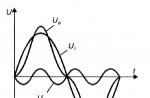
On fig. the changes in the electrical parameters in the winding are shown below. Below are the explanations:

Voltage regulator created using a combined circuit
- The values (n1) and (n2) are different rotor speeds at which the corresponding measurements were made (the frequency n2 is greater than n1).
- It can be seen that t on (the turn-on time of the winding) is greater on the upper graph, and less on the lower graph. Thus, with an increase in the speed of rotation, the winding creates a magnetic field for less time.
- The parameter t off (the time during which the switch-off occurs) explains the meaning of the second stage of the process. With acceleration of rotation and increase in voltage in the winding, the current decreases. This process provides the desired result, reducing the output voltage.
Features of regulators of different types
The diagram of a standard vibration type product is shown in the following figure:

Changing electrical parameters
This list shows the main parts of the design:
- 1 - spring;
- 2 - anchor;
- 3 - yoke;
- 4 - core;
- 5, 6, 9, 10, 15 - windings of the relay, current limiter and regulator;
- 7, 12, 17 - movable group of contacts;
- 8, 11, 16 - fixed group of contacts;
- 14 - shunt;
- 13, 18 and 19 - resistors.
It is clear that numerous mechanical contacts and moving parts reduce reliability. Such a relay voltage regulator of the generator has a large weight and impressive dimensions.
Below is a schematic diagram of one of the BOSCH regulators, which uses only electronic element base:

Schematic diagram of the BOSCH voltage regulator
This solution significantly improves reliability. It does not require a lot of space to accommodate a compact product. This device, subject to production technologies, is highly resistant to vibrations and temperature extremes.
In some versions, the board is filled with a compound, which further increases the protective properties and extends the service life in the most severe conditions.
Below are the features of individual elements:
- On the right side of the figure (part 2) is a diagram of an oscillator with rectifier diodes. At the top is a light that indicates the device is turned on.
- On the left side (part 1) is the electrical circuit of the regulator.
- (VT2) and (VT3) are the designation of transistors connected according to the classical scheme to increase the gain.
As a rule, such devices use an electronic element created in a single package and even on a single silicon chip.
- The zener diode is marked with symbols (VD1). This device does not pass current to a level that determines the stabilization voltage. As soon as the threshold value is broken, the current begins to flow through the corresponding circuit.
This circuit diagram performs its functions as follows:
- With the help of resistors (R1) and (R2), the voltage from the generator output is divided in the required proportion and fed to the zener diode.
- While the rotor speed is low, its level is insufficient to break through the semiconductor junction of the zener diode. In such a situation, no current can flow through the corresponding circuit. It does not arrive at the base (VT1). Therefore, the transistor is closed.
- The current passes to the base (VT2) along a different path, through (R6). This dual transistor is open. In this state, the winding is connected to the power circuit and creates a magnetic field.
- As the speed increases, or with a certain change in resistance in the load, the voltage at the generator output increases. If a certain threshold is exceeded, the semiconductor junction of the zener diode will be broken.
- After that, the current will go to the base (VT1) and open it. The path of current through the collector-emitter path to the ground point will be open. The semiconductor junction of the composite transistor will close, which will break the power supply circuit of the winding.
- When the excitation current level decreases, the rotor speed slows down, the voltage level drops, and the zener diode junction closes.
Health check
The consistent development of technology opens up new opportunities for improving the consumer parameters of electronics while reducing weight and size. In modern cars, even the last scheme, from the options discussed above, will look like an anachronism.
Modern regulators are more complex devices. They are distinguished by increased accuracy of control and stabilization of the generator voltage. They are created in sealed cases, filled with compound mixtures, which, after solidification, create reliable protection against moisture penetration and other external influences. These structures are non-separable, therefore, in the event of a breakdown, they are completely replaced.
It can be stated that in practice there is no repair not only in specialized workshops. Private craftsmen and amateurs to do everything themselves have to go to a specialized store to purchase the necessary assembly assembly. Thus, it is not the ability to solder individual elements and understand their performance, but general diagnostics that is of primary importance. To carry it out, you will need a tester and probes, a 12 V light bulb and a set of connecting wires, a charger.

Regulator mounted on the generator housing
Below is an algorithm of actions that will help to localize the malfunction. These recommendations are general. Therefore, it is necessary to take into account the special recommendations of the manufacturer for the correct dismantling of the voltage regulator and other components:
- With the engine turned off, the voltage at the battery terminals is measured (the norm is in the range from 11.9 to 12.7 V).
- After starting the power unit, a new voltage level is fixed, which should increase from the initial level by 0.9-1.1 V.
- Gradually increase engine speed. For convenience, this procedure is best performed with a partner. At medium - the voltage rises to 13.8-14.1 V. At the highest - up to 14.4-14.5 V.
If the acceleration of the rotation of the generator rotor does not affect the voltage level, then the regulator may break.
For a more accurate diagnosis, you will need to dismantle it and connect it according to the following scheme:

Regulator test circuit
When you turn on the charger and gradually increase the level to 14.4-14.5 V, the lamp will light up. As soon as this threshold is exceeded, it will turn off. When the voltage drops, the lamp will light up again. A malfunction is indicated not only by the absence of the described reactions, but also by the operation of the device at a higher voltage level. Under such conditions, the battery will be overcharged, which will reduce its life. After the diagnosis is completed, you can decide to replace the damaged regulator.
Video. Checking the voltage regulator.
In order to use the above technology in a timely manner, it is necessary to pay attention to deviations from the norm of the battery charge. Before dismantling the regulator, you should make sure that there are no oxide contaminations in the places of electrical contacts. In some situations, simply clearing the connections will resolve the issue. To prevent the occurrence of such problems in the future, it is recommended to use special means to protect contacts.
Rice. 1. Ways to control the excitation current: G - generator with parallel excitation; W in - excitation winding; R d - additional resistance; R - ballast resistance; K - current switch (regulating body) in the excitation circuit; a, b, c, d, e are indicated in the text.
A modern automobile internal combustion engine (ICE) operates in a wide range of speed changes (900: .. 6500 rpm). Accordingly, the rotor speed of the automobile generator changes, and hence its output voltage.
The dependence of the generator output voltage on the internal combustion engine speed is unacceptable, since the voltage in the vehicle's on-board network must be constant, and not only when the engine speed changes, but also when the load current changes. The function of automatic voltage regulation in the automobile generator is performed by a special device - automotive alternator voltage regulator. This material is devoted to the consideration of voltage regulators of modern automotive alternators.
Voltage regulation in generators with electromagnetic excitation
Ways of regulation. If the main magnetic field of the generator is induced by electromagnetic excitation, then the electromotive force E g of the generator can be a function of two variables: the frequency n of rotation of the rotor and the current I in in the excitation winding - E g \u003d f (n, I c).
It is this type of excitation that takes place in all modern automotive alternators that operate with a parallel excitation winding.
When the generator is running without load, its voltage U g is equal to its electromotive force EMF E g:
U g \u003d E g \u003d SF n (1).
Voltage U g of the generator under current I n load is less than the EMF E g by the amount of voltage drop across the internal resistance r g of the generator, i.e. can be written that
E g \u003d U g + I n r g \u003d U g (1 + β) (2).
The value β \u003d I n r g / U g is called the load factor.
From a comparison of formulas 1 and 2, it follows that the generator voltage
U g = nSF/(1 + β), (3)
where C is a constant design factor.
Equation (3) shows that both at different frequencies (n) of rotation of the generator rotor (n \u003d Var), and with a changing load (β \u003d Var), the stability of the voltage U g of the generator can only be obtained by a corresponding change in the magnetic flux Ф.
The magnetic flux Ф in a generator with electromagnetic excitation is formed by the magnetomotive force F in \u003d W I in the windings W in the excitation (W is the number of turns of the winding W in) and can be easily controlled using the current I in the excitation winding, i.e. F \u003d f (I c). Then U g \u003d f 1 which allows you to keep the voltage U g of the generator within the specified control limits for any changes in its speed and load by the appropriate choice of the control function f (I c).
The automatic function f (I c) of regulation in voltage regulators is reduced to a decrease in the maximum value of current I c in the excitation winding, which occurs at I c = U g / R w (R w is the active resistance of the excitation winding) and can be reduced in several ways ( Fig. 1): connecting to the winding W in parallel (a) or in series (b) additional resistance R d: shorting the excitation winding (c); rupture of the excitation current circuit (d). The current through the excitation winding can also be increased by shorting the series additional resistance (b).
All these methods change the excitation current stepwise, i.e. intermittent (discrete) current regulation takes place. In principle, analog regulation is also possible, in which the value of the series additional resistance in the excitation circuit changes smoothly (e).
But in all cases, the voltage U g of the generator is kept within the specified control limits by the appropriate automatic adjustment of the excitation current.
Discrete - pulse regulation
In modern automotive generators, the magnetomotive force F in the excitation windings, and hence the magnetic flux Ф, is changed by periodic interruption or an abrupt decrease in the current I in excitations with a controlled interruption frequency, i.e. apply discrete-pulse regulation of the operating voltage U g of the generator (previously, analog regulation was used, for example, in coal-fired voltage regulators).
The essence of discrete-pulse regulation will become clear from the consideration of the principle of operation of the generator set, consisting of the simplest contact-vibration voltage regulator, and an alternating current generator (ACG).

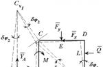
Rice. 2. Functional (a) and electrical (b) circuits of a generator set with a vibration voltage regulator.
A functional diagram of a generator set operating in conjunction with an onboard battery (ACB) is shown in fig. 2a, and the electrical circuit - in fig. 26.
The generator includes: phase windings W f on the stator ST, rotating rotor R, power rectifier VP on semiconductor diodes VD, excitation winding W in (with active resistance R w). The mechanical energy of rotation A m \u003d f (n) the generator rotor receives from the internal combustion engine. The vibration voltage regulator RN is made on an electromagnetic relay and includes a switching element CE and a measuring element IE.
The switching element of the KE is a vibrating electrical contact K, closing or opening the additional resistance R d, which is connected in series with the excitation winding W in the generator. When the switching element is triggered (contact K opens), a signal τR d is formed at its output (Fig. 2a).
The measuring element (ME, in Fig. 2a) is that part of the electromagnetic relay that implements three functions:
- the comparison function (CS) of the mechanical elastic force F n of the return spring P with the magnetomotive force F s = W s I s of the relay winding S (W s is the number of turns of the winding S, I s is the current in the relay winding), while the result of the comparison is the generated in the gap with period T (T = t p + t h) armature oscillations N;
- the function of the sensitive element (SE) in the feedback circuit (DSP) of the voltage regulator, the sensitive element in the vibration regulators is the winding S of the electromagnetic relay, connected directly to the voltage U g of the generator and to the battery (to the latter through the ignition key VZ);
- the function of the master device (ZU), which is implemented using a return spring P with an elastic force F p and a reference force F o.
The operation of a voltage regulator with an electromagnetic relay can be clearly explained using the speed characteristics of the generator (Fig. 3 and 4).

Rice. 3. Change U g, I c, R b in time t: a - dependence of the current value of the generator output voltage on time t - U g \u003d f (t); b - dependence of the current value in the excitation winding on time - I c \u003d f (t); c - dependence of the arithmetic mean value of the resistance in the excitation circuit on time t - R b \u003d f (t); I - time corresponding to the frequency (n) of rotation of the generator rotor.
While the voltage U g of the generator is lower than the voltage U b of the battery (U g
With an increase in the speed of the internal combustion engine, the generator voltage increases and when a certain value is reached U max) > U b) the magnetomotive force F s of the relay winding becomes greater than the force F p of the return spring P, i. F s \u003d I s W s > F p. The electromagnetic relay is activated and contact K opens, while additional resistance is included in the excitation winding circuit.
Even before contact K opens, the current I in in the field winding reaches its maximum value I in max \u003d U g R w > I wb, from which, immediately after contact K opens, it begins to fall, tending to its minimum value I in min \u003d U g /(Rw + Rd). Following the drop in the excitation current, the generator voltage begins to decrease accordingly (U g \u003d f (I c), which leads to a drop in current I s \u003d U g / R s in the relay winding S and contact K is again opened by the force of the return spring P (F p > F s) By the time the contact K opens, the generator voltage U g becomes equal to its minimum value U min, but remains slightly higher than the battery voltage (U gmin > U b).
Starting from the moment contact K opens (n = n min, Fig. 3), even with a constant frequency n of rotation of the generator rotor, the armature N of the electromagnetic relay enters the mechanical self-oscillation mode and contact K, vibrating, starts periodically, with a certain switching frequency f to \u003d I / T \u003d I / (t p + t h) then close, then open the additional resistance R d in the generator excitation circuit (green line in the section n \u003d n cf \u003d const, Fig. 3). In this case, the resistance R in in the excitation current circuit changes abruptly from the value of R w to the value of R w + R d.
Since during the operation of the voltage regulator contact K vibrates with a sufficiently high frequency f to switching, then R in \u003d R w + τ p where the value τ p is the relative time of the open state of contact K, which is determined by the formula τ p \u003d t p / ( t c + t p), I / (t c + t p) \u003d f to - switching frequency. Now, the average value of the excitation current, which has been established for a given frequency f to switching, can be found from the expression:
I cf \u003d U g cf / R c \u003d U g cf / (R w + τ p R d) \u003d U g cf / (R w + R d t p / f k),
where R in is the arithmetic mean (effective) value of the pulsating resistance in the excitation circuit, which also increases with an increase in the relative time τ p of the open state of the contact K (green line in Fig. 4).

Rice. 4. Speed characteristics of the generator.
Switching processes with excitation current
Let us consider in more detail what happens when switching with the excitation current. When contact K is closed for a long time, the maximum excitation current I in \u003d U g / R w flows through the winding W in the excitation.
However, the excitation winding W in the generator is an electrically conductive coil with a large inductance and a massive ferromagnetic core. As a consequence, the current through the excitation winding after the contact K is closed increases with deceleration. This is because the rate of current rise is hindered by hysteresis in the core and counteracting the rising current - the self-induction EMF of the coil.
When contact K is opened, the excitation current tends to a minimum value, the value of which, with a permanently open contact, is determined as I in \u003d U g / (R w + R d). Now the EMF of self-induction coincides in direction with the decreasing current and somewhat prolongs the process of its decrease.
It follows from the foregoing that the current in the excitation winding cannot change instantly (stepwise, as an additional resistance R d) either when closing or when opening the excitation circuit. Moreover, at a high vibration frequency of contact K, the excitation current may not reach its maximum or minimum value, approaching its average value (Fig. 4), since the value t p = τ p / f k increases with increasing frequency f to switching, and the absolute time t C of the closed state of contact K decreases.
From joint consideration of the diagrams shown in fig. 3 and fig. 4, it follows that the average value of the excitation current (red line b in Fig. 3 and Fig. 4) decreases with increasing speed n, since this increases the arithmetic mean value (green line in Fig. 3 and Fig. 4) of the total, pulsating in time, resistance R in the excitation circuit (Ohm's law). In this case, the average value of the generator voltage (U cf in Fig. 3 and Fig. 4) remains unchanged, and the output voltage U g of the generator pulsates in the range from U max to U min.
If the generator load increases, then the regulated voltage U g initially drops, while the voltage regulator increases the current in the field winding so that the generator voltage rises back to its original value.
Thus, when the generator load current changes (β = V ar), the regulation processes in the voltage regulator proceed in the same way as when the rotor speed changes.
Regulated voltage ripple. At a constant frequency n of rotation of the generator rotor and at a constant load, the operating excitation current ripples (ΔI in in Fig. 46) induce the corresponding (in time) ripples of the regulated generator voltage.
The amplitude of the ripples ΔU g - 0.5 (U max - U min) * voltage regulator U g does not depend on the amplitude of tone ripples ΔI in in the excitation winding, since it is determined by the regulation interval specified using the measuring element of the regulator. Therefore, voltage ripples U g at all frequencies of rotation of the generator rotor are almost the same. However, the rate of rise and fall of voltage U g in the control interval is determined by the rate of rise and fall of the excitation current and, ultimately, the speed (n) of the generator rotor.
* It should be noted that ripples 2ΔU g are an inevitable and harmful side effect of the operation of the voltage regulator. In modern generators, they are closed to ground by a shunt capacitor Csh, which is installed between the positive terminal of the generator and the case (usually Csh \u003d 2.2 μF)
When the load of the generator and the frequency of rotation of its rotor do not change, the vibration frequency of the contact K is also unchanged (f k \u003d I / (t c + t p) \u003d const). In this case, the voltage U g of the generator pulsates with an amplitude ΔU p \u003d 0.5 (U max - U min) about its average value U cf.
When the rotor speed changes, for example, upwards or when the generator load decreases, the time t c of the closed state becomes less than the time t p of the open state (t c
With a decrease in the frequency of the generator rotor (n↓), or with an increase in load (β), the average value of the excitation current and its ripple will increase. But the generator voltage will continue to fluctuate with an amplitude ΔU g around a constant value U g cf.
The constancy of the average voltage value U g of the generator is explained by the fact that it is determined not by the operating mode of the generator, but by the design parameters of the electromagnetic relay: the number of turns W s of the relay winding S, its resistance R s , the value of the air gap σ between the armature N and the yoke M, as well as force F p of the return spring P, i.e. the value U cf is a function of four variables: U cf = f(W s , R s , σ, F p).
By bending the support of the return spring P, the electromagnetic relay is adjusted to the value U cf so that at the lower rotor speed (n = n min - Fig. 3 and Fig. 4) contact K would begin to open, and the excitation current would have time to reach its maximum value I in \u003d U g / R w. Then the pulsations ΔI in and the time t z, the closed state are maximum. This sets the lower limit of the operating range of the controller (n = n min). At medium rotor speeds, the time t c is approximately equal to the time t p, and the excitation current ripples become almost two times smaller. At a rotational speed n close to the maximum (n = n max - Fig. 3 and Fig. 4), the average value of the current I in and its ripple ΔI in are minimal. At n max, the self-oscillations of the regulator are disrupted and the voltage U g of the generator begins to increase in proportion to the rotor speed. The upper limit of the operating range of the regulator is set by the value of the additional resistance (at a certain resistance value R w).
conclusions. The foregoing about discrete-pulse control can be summarized as follows: after starting the internal combustion engine (ICE), with an increase in its speed, there comes a moment when the generator voltage reaches the upper control limit (U g = U max). At this moment (n = n min), the switching element of the CE opens in the voltage regulator and the resistance in the excitation circuit increases abruptly. This leads to a decrease in the excitation current and, as a result, to a corresponding voltage drop U g of the generator. The voltage drop U g below the minimum control limit (U g = U min) leads to a reverse circuit of the switching element of the KE and the excitation current begins to increase again. Further, from this moment, the voltage regulator enters the self-oscillation mode and the process of switching the current in the excitation winding of the generator is periodically repeated, even at a constant frequency of rotation of the generator rotor (n = const).
With a further increase in the frequency of rotation n, proportionally to it, the time t c of the closed state of the switching element of the CE begins to decrease, which leads to a smooth decrease (in accordance with the increase in frequency n) of the average value of the excitation current (red line in Fig. 3 and Fig. 4) and amplitude ΔI in its pulsation. Due to this, the voltage U g of the generator also begins to pulsate, but with a constant amplitude ΔU g near its average value (U g = U cf) with a sufficiently high oscillation frequency.
The same processes of current switching I in and voltage ripple U g will also take place when the generator load current changes (see formula 3).
In both cases, the average voltage U g of the generator remains unchanged over the entire range of operation of the voltage regulator in frequency n (U g cf = const, from n min to n max) and when the generator load current changes from I g = 0 to I g = max .
In the foregoing is the basic principle of regulating the voltage of the generator using an intermittent change in the current in its excitation winding.
Electronic voltage regulators for automotive alternators
The vibration voltage regulator (VRN) considered above with an electromagnetic relay (EM relay) has a number of significant disadvantages:
- as a mechanical vibrator VRN is unreliable;
- contact K in the EM relay burns out, which makes the regulator short-lived;
- VRN parameters depend on temperature (the average value U cf of the operating voltage U g of the generator floats);
- VRN cannot operate in the mode of complete de-energization of the field winding, which makes it insensitive to changes in the output voltage of the generator (high voltage ripple U g) and limits the upper limit of the voltage regulator;
- electromechanical contact K of the electromagnetic relay limits the value of the maximum excitation current to 2 ... 3 A, which does not allow the use of vibration controllers on modern high-power alternators.
With the advent of semiconductor devices, it became possible to replace the contact K of the EM relay with the emitter-collector junction of a powerful transistor with its base control by the same contact K of the EM relay.
This is how the first contact-transistor voltage regulators appeared. In the future, the functions of an electromagnetic relay (SU, CE, UE) were fully implemented using low-level (low-current) electronic circuits on semiconductor devices. This made it possible to manufacture purely electronic (semiconductor) voltage regulators.
A feature of the operation of the electronic regulator (ERN) is that it does not have an additional resistor R d, i.e. in the excitation circuit, almost complete shutdown of the current in the excitation winding of the generator is realized, since the switching element (transistor) in the closed (open) state has a sufficiently large resistance. This makes it possible to control a larger excitation current and at a higher switching speed. With such a discrete-pulse control, the excitation current has a pulsed character, which makes it possible to control both the frequency of current pulses and their duration. However, the main function of the ERN (maintaining a constant voltage U g at n = Var and at β = Var) remains the same as in the VRN.
With the development of microelectronic technology, voltage regulators first began to be produced in a hybrid version, in which packageless semiconductor devices and attached miniature radio elements were included in the electronic circuit of the regulator along with thick-film microelectronic resistive elements. This made it possible to significantly reduce the weight and dimensions of the voltage regulator.
An example of such an electronic voltage regulator is the Ya-112A hybrid-integrated regulator, which is installed on modern domestic generators.
Regulator Ya-112A(see the diagram in Fig. 5) is a typical representative of the circuit solution for the problem of discrete-pulse regulation of the voltage U g of the generator by current I in excitation. But in the design and technological performance, currently produced electronic voltage regulators have significant differences.
Rice. 5. Schematic diagram of the Ya-112A voltage regulator: R1 ... R6 - thick-film resistors: C1, C2 - hinged miniature capacitors; V1...V6 - unpackaged semiconductor diodes and transistors.
As for the design of the Ya-112A regulator, all of its semiconductor diodes and triodes are unpackaged and mounted using a hybrid technology on a common ceramic substrate together with passive thick-film elements. The entire regulator block is hermetically sealed.
The Ya-112A regulator, like the vibration voltage regulator described above, operates in an intermittent (key) mode, when the control of the excitation current is not analog, but discrete-pulse.
The principle of operation of the voltage regulator Ya-112A of automobile generators
As long as the voltage U g of the generator does not exceed a predetermined value, the output stage V4-V5 is in a constantly open state and the current I in the field windings directly depends on the voltage U g of the generator (section 0-n in Fig. 3 and Fig. 4). As the generator speed increases or its load decreases, U g becomes higher than the response threshold of the sensitive input circuit (V1, R1-R2), the zener diode breaks through and the output stage V4-V5 closes through the amplifying transistor V2. In this case, the current I in in the excitation coil is turned off until U g again becomes less than the specified value U min. Thus, during the operation of the regulator, the excitation current flows intermittently through the excitation winding, changing from I in \u003d 0 to I in \u003d I max. When the excitation current is cut off, the generator voltage does not immediately drop, since the inertia of the demagnetization of the rotor takes place. It may even slightly increase with an instantaneous decrease in the load current of the generator. The inertia of the magnetic processes in the rotor and the self-induction EMF in the excitation winding exclude an abrupt change in the generator voltage both when the excitation current is turned on and when it is turned off. Thus, the sawtooth voltage ripple U g of the generator remains with electronic regulation.
The logic of constructing a circuit diagram of an electronic regulator is as follows. V1 - a zener diode with a divider R1, R2 form the input current cut-off circuit I in at U g\u003e 14.5 V; transistor V2 controls the output stage; V3 - blocking diode at the input of the output stage; V4, V5 - powerful transistors of the output stage (composite transistor) connected in series with the excitation winding (switching element of the CE for current I c); V6 shunt diode to limit the self-induction EMF of the field winding; R4, C1, R3 is a feedback circuit that accelerates the process of cutting off the current I in excitation.
 An even more advanced voltage regulator is an integrated electronic regulator. This is a design in which all its components, except for a powerful output stage (usually a composite transistor), are implemented using thin-film microelectronic technology. These regulators are so miniature that they practically do not take up any space and can be installed directly on the generator housing in a brush holder.
An example of IRN design is the BOSCH-EL14V4C regulator, which is installed on alternators with a power of up to 1 kW (Fig. 6).
Depending on the device and the principle of operation, the relay-voltage regulators of the generator in the car are divided into several types: built-in, external, three-level and others. Theoretically, such a device can be made independently, the easiest and cheapest option in terms of implementation is to use a shunt device.
[ Hide ]
Purpose of the relay-regulator
The generator voltage regulator is designed to stabilize the current in the installation. When the engine is running, the voltage in the electrical system of the car must be at the same level. But since the crankshaft rotates at different speeds and the engine speed is not the same, the generator unit produces different voltages. Without adjusting this parameter, malfunctions in the operation of the electrical equipment and appliances of the machine may occur.
The relationship of auto current sources
Every car uses two power sources:
- Battery - required to start the power unit and primary excitation of the generator set. The battery consumes and stores energy when recharging.
- Generator. Designed for power and needed in order to generate energy regardless of the speed. The device allows you to recharge the battery when working at high speeds.
In any electrical network, both nodes must be working. If the DC generator fails, the battery will last no more than two hours. Without a battery, the power unit will not start, which drives the rotor of the generator set.
The LR West channel spoke about the malfunctions of the electrical networks in Land Rover vehicles, as well as the relationship between the battery and generators.
Voltage regulator tasks
Tasks performed by an electronic adjustable device:
- change in the value of the current in the excitation winding;
- the ability to withstand the range from 13.5 to 14.5 volts in the mains, as well as at the battery terminals;
- power off the excitation winding when the power unit is off;
- battery charging function.
"People's Auto Channel" spoke in detail about the purpose, as well as about the tasks that the voltage regulator in the car performs.
Varieties of relay-regulators
There are several types of automotive relay-regulators:
- external - this type of relay allows you to increase the maintainability of the generator unit;
- built-in - installed in the rectifier plate or brush assembly;
- changing by minus - equipped with an additional cable;
- plus-adjustable - characterized by a more economical connection scheme;
- for installation in alternating current units - the voltage cannot be regulated when applied to the excitation winding, since it is installed in the generator;
- for DC devices - relay-regulators have the function of cutting off the battery when the engine is not running;
- two-level relays - today they are practically not used, in them the adjustment is carried out by springs and a lever;
- three-level - equipped with a comparing module circuit, as well as a matching signaling device;
- multilevel - equipped with 3-5 additional resistor elements, as well as a control system;
- transistor samples - are not used on modern vehicles;
- relay devices - are characterized by more improved feedback;
- relay-transistor - have a universal circuit;
- microprocessor relays - characterized by small size, as well as the ability to smoothly change the lower or upper threshold;
- integral - are installed in the brush holders, therefore, when they are worn, they change.
Relay-regulators DC
In such units, the connection diagram looks more complicated. If the machine is stationary and the engine is not running, the generator set must be disconnected from the battery.
When performing a relay test, you must ensure that three options are available:
- battery cut-off when the vehicle is parked;
- limiting the maximum current parameter at the output of the unit;
- the ability to change the voltage parameter for the winding.
Relay-regulators of alternating current
Such devices are characterized by a more simplified test scheme. The car owner needs to diagnose the magnitude of the voltage on the excitation winding, as well as at the output of the unit.
If an alternator is installed in the car, then it will not work to start the engine “from the pusher”, unlike a direct current unit.
Built-in and external relay-regulators
The procedure for changing the voltage value is performed by the device at a specific installation location. Accordingly, the built-in regulators act on the generator unit. And the external type of relay is not connected to it and can be connected to the ignition coil, then its work will only be aimed at changing the voltage in this area. Therefore, before performing diagnostics, the car owner must make sure that the part is connected correctly.
The Sovering TVi channel spoke in detail about the purpose, as well as the principle of operation of this type of device.
Two-level
The principle of operation of such devices is as follows:
- Current passes through the relay.
- As a result of the formation of a magnetic field, the lever is attracted.
- A spring with a specific force is used as a comparing element.
- When the voltage increases, the contact elements open.
- Less current is applied to the excitation winding.
In VAZ cars, mechanical two-level devices were previously used for regulation. The main drawback was the rapid wear of structural components. Therefore, instead of mechanical, electronic regulators were installed on these models of machines.
These details were based on:
- voltage dividers, which were assembled from resistor elements;
- a zener diode was used as a driving part.
Due to the complex wiring diagram and inefficient voltage level control, this type of device has become less common.
Three-level
This type of regulators, as well as multilevel ones, are more advanced:
- The voltage is supplied from the generator device to a special circuit and passes through a divider.
- The received data is processed, the actual voltage level is compared with the minimum and maximum values.
- The mismatch pulse changes the current parameter that is supplied to the excitation winding.
Three-level devices with frequency modulation do not have resistances, but the frequency of operation of the electronic key in them is higher. For control, special logic circuits are used.
plus and minus control
Schemes for negative and positive contacts differ only in connection:
- when installed in a positive gap, one brush is connected to ground, and the second goes to the relay terminal;
- if the relay is installed in the minus gap, then one brush element must be connected to the plus, and the second - directly to the relay.
But in the second case, another cable will appear. This is due to the fact that these relay modules belong to the class of devices of the active type. For its operation, a separate power supply is required, so the plus is connected individually.
Photo gallery "Types of generator voltage relay-regulator"
This section contains photos of some types of devices.
Remote type devices  Built-in regulator
  Transistor-relay type
  Integral device
  DC generator device
  AC regulator
  Two-tier device type
  Three-level control device
The principle of operation of the relay-regulator
The presence of a built-in resistor device, as well as special circuits, makes it possible for the regulator to compare the voltage parameter that the generator produces. If the value is too high, the controller is disabled. This allows you to prevent overcharging of the battery and failure of electrical equipment that is powered by the mains. Malfunctions of the device will lead to battery failure.
switch winter and summer
The generating device works stably regardless of the ambient temperature and season. When its pulley is set in motion, current is generated. But in the cold season, the internal structural elements of the battery can freeze. Therefore, the battery charge is restored worse than in the heat.
The switch for changing the season of operation is located on the relay housing. Some models are equipped with special connectors, you need to find them and connect the wires in accordance with the diagram and the symbols printed on them. The switch itself is a device by which the voltage level at the battery terminals can be increased to 15 volts.
How to remove the relay-regulator?
Removing the relay is allowed only after disconnecting the terminals from the battery.
To dismantle the device with your own hands, you will need a screwdriver with a Phillips or flat tip. It all depends on the bolt that secures the regulator. The generator unit, as well as the drive belt, do not need to be dismantled. The cable is disconnected from the regulator and the bolt that secures it is unscrewed.
User Viktor Nikolayevich spoke in detail about the dismantling of the regulatory mechanism and its subsequent replacement with a car.
Symptoms
“Symptoms” that will require the regulator to be checked or repaired:
- when the ignition is activated, a light indicator of a discharged battery appears on the control panel;
- the icon on the dashboard does not disappear after starting the engine;
- the brightness of the glow of the optics may be too low and increase with increasing crankshaft speed and pressing the gas pedal;
- the power unit of the machine is difficult to start the first time;
- The car battery is often discharged;
- with an increase in the number of revolutions of the internal combustion engine more than two thousand per minute, the bulbs on the control panel turn off automatically;
- the dynamic properties of the vehicle are reduced, which is especially evident at increased crankshaft speeds;
- the battery may be leaking.
Possible causes of malfunctions and consequences
The need to repair the generator voltage regulator relay will arise with such problems:
- interturn circuit of the winding device;
- short circuit in the electrical circuit;
- breakdown of the rectifier element as a result of breakdown of diodes;
- errors made when connecting the generating set to the battery terminals, reversal;
- the ingress of water or other liquid into the body of the regulatory device, for example, in high humidity on the street or when washing a car;
- mechanical malfunctions of the device;
- natural wear of structural elements, in particular, brushes;
- poor quality of the device used.
As a result of a malfunction, the consequences can be serious:
- High voltage in the car's electrical network will damage the electrical equipment. The microprocessor control unit of the machine may fail. Therefore, it is not allowed to disconnect the battery terminal clamps when the power unit is running.
- Overheating of the winding device as a result of an internal short circuit. Repairs will be costly.
- Breakage of the brush mechanism will lead to a malfunction of the generator set. The knot may jam, the drive strap may break.
User Snickerson spoke about the diagnostics of the regulatory mechanism, as well as the reasons for its failure in cars.
Diagnostics of the relay-regulator
It is necessary to check the operation of the regulatory device using a tester - a multimeter. It must first be set to voltmeter mode.
Embedded
This mechanism is usually built into the brush assembly of the generator set, so level diagnostics of the device will be required.
The check is done like this:
- The protective cover is being dismantled. Using a screwdriver or wrench, the brush assembly is loosened, it must be brought out.
- The wear of the brush elements is checked. If their length is less than 5 mm, then replacement is mandatory.
- Checking the generator device using a multimeter is performed together with the battery.
- The negative cable from the current source closes to the corresponding plate of the regulatory device.
- The positive contact from the charging equipment or battery is connected to the same output on the relay connector.
- Then the multimeter is set to the operating range from 0 to 20 volts. The probes of the device are connected to the brushes.
In the operating range from 12.8 to 14.5 volts, there should be voltage between the brush elements. If the parameter increases by more than 14.5 V, then the tester needle should fall to zero.
When diagnosing the built-in relay-voltage regulator of the generator, it is allowed to use a control light. The light source should turn on at a certain voltage interval and go out if this parameter increases more than the required value.
The cable that controls the tachometer must be ringed with a tester. On diesel vehicles, this conductor is designated W. The resistance level of the wire should be approximately 10 ohms. If this parameter falls, this indicates that the conductor is broken and needs to be replaced.
remote
The diagnostic method for this type of device is carried out in a similar way. The only difference is that the regulator relay does not need to be removed and removed from the generator set housing. You can diagnose the device with the power unit running, changing the crankshaft speed from low to medium to high. With an increase in their number, it is necessary to activate the optics, in particular, distant lighting, as well as the radio, stove and other consumers.
The channel "AvtotechLife" talked about self-diagnosis of the regulatory device, as well as about the features of this task.
Independent connection of the relay-regulator to the on-board network of the generator (step by step instructions)
When installing a new regulator device, the following points must be taken into account:
- Before performing the task, it is imperative to diagnose the integrity, as well as the reliability of the contacts. This is a cable that runs from the vehicle body to the generator set housing.
- Then the terminal clamp B of the regulator element is connected to the positive contact of the generating set.
- It is not recommended to use twisted wires when making a connection. They heat up and become unusable after a year of operation. Soldering should be used.
- It is recommended to replace the regular conductor with a wire with a cross section of at least 6 mm2. Especially if a new generator is installed instead of the factory one, which is designed to operate at currents above 60 A.
- The presence of an ammeter in the generator-battery circuit allows you to determine the power of power sources at a specific time.
Remote controller connection diagram
Wiring diagram for remote type devices
This device is installed after the wire is determined, into the gap of which it will connect:
- In older versions of Gazelles and RAF, mechanisms 13.3702 are used. They are made in a metal or polymer case and are equipped with two contact elements and brushes. They are recommended to be connected to a negative circuit break, the outputs are usually marked. The positive contact is taken from the ignition coil. And the output Ш of the relay is connected to a free contact on the brushes.
- In VAZ cars, devices 121.3702 are used in a black or white case, there are also double modifications. In the latter, if one of the parts breaks down, the second regulator will remain operational, but you need to switch to it. The device is installed in a break in the positive circuit with terminal 15 to the contact of the B-VK coil. The conductor number 67 is connected to the brushes.
In newer versions of the VAZ, the relays are installed in the brush mechanism and connected to the ignition switch. If the car owner replaces the standard unit with an AC unit, then the connection must be made taking into account the nuances.
More about them:
- The need to fix the unit to the body of the vehicle is determined by the car owner independently.
- Instead of a positive output, contact B or B+ is used here. It must be connected to the car's electrical network through an ammeter.
- The remote type of devices in such cars is usually not used, and the built-in regulators are already integrated into the brush mechanism. From it comes one cable, designated as D or D +. It must be connected to the ignition switch.
In vehicles with diesel engines, the generator unit can be equipped with a W output - it is connected to the tachometer. This contact can be ignored if the unit is placed on a gasoline modification of the car.
User Nikolai Purtov spoke in detail about installing and connecting remote devices to a car.
Connectivity Check
The motor must be running. And the voltage level in the car's electrical network will be controlled depending on the number of revolutions.
Perhaps, after installing and connecting a new generator device, the car owner will encounter difficulties:
- when the power unit is activated, the generator unit starts up, the voltage value is measured at any speed;
- and after turning off the ignition, the vehicle engine runs and does not turn off.
The problem can be solved by disconnecting the excitation cable, only after that the engine will stop.
Engine stalling can occur when the clutch is released while pressing the brake pedal. The cause of the malfunction is the residual magnetization, as well as the constant self-excitation of the winding of the unit.
In order not to encounter such a problem in the future, you can add a light source to the break in the exciting cable:
- the light will be on when the generator is off;
- when the unit is started, the indicator goes out;
- the amount of current that passes through the light source will not be sufficient to excite the winding.
The Altevaa TV channel talked about checking the connection of the regulatory device after connecting it to the 6-volt network of the motorcycle.
Tips for increasing the life of the relay-regulator
In order to prevent a quick failure of the regulatory device, it is necessary to adhere to several rules:
- The generator set must not be heavily contaminated. From time to time, you should perform a visual diagnosis of the condition of the device. In case of serious contamination, the unit is removed and cleaned.
- The tension of the drive belt should be checked periodically. If necessary, it is stretched.
- It is recommended to monitor the condition of the generator set windings. They must not be allowed to darken.
- It is necessary to check the quality of the contact on the control cable of the regulatory mechanism. Oxidation is not allowed. When they appear, the conductor is cleaned.
- Periodically, you should diagnose the voltage level in the electrical network of a car with the engine running and turned off.
How much does a regulator cost?
The cost of the device depends on the manufacturer and type of regulator.
Is it possible to make a regulator with your own hands?
An example is considered on the regulatory mechanism for a scooter. The main nuance is that for correct operation, it will be necessary to disassemble the generating unit. With a separate conductor, it is necessary to bring out the mass cable. The assembly of the device is carried out according to the scheme of a single-phase generator.
Action algorithm:
- The generator unit is disassembled, the stator element is removed from the scooter motor.
- On the left around the windings there is a mass, it must be soldered.
- Instead, a separate cable is soldered for winding. Then this contact is brought out. This conductor will be one end of the winding.
- The generator unit is being reassembled. These manipulations are carried out so that two cables come out of the unit. They will be used.
- Then, a shunt device is connected to the received contacts. At the final stage, a yellow cable from the old relay is connected to the positive terminal of the battery.
Video "Visual guide to assembling a homemade regulator"
User Andrey Chernov clearly showed how to independently make a relay for the generator set of a VAZ 2104 car.
Depending on the device and the principle of operation, the relay-voltage regulators of the generator in the car are divided into several types: built-in, external, three-level and others. Theoretically, such a device can be made independently, the easiest and cheapest option in terms of implementation is to use a shunt device.
[ To uncover]
Purpose of the relay-regulator
The generator voltage regulator is designed to stabilize the current in the installation. When the engine is running, the voltage in the electrical system of the car must be at the same level. But since the crankshaft rotates at different speeds and the engine speed is not the same, the generator unit produces different voltages. Without adjusting this parameter, malfunctions in the operation of the electrical equipment and appliances of the machine may occur.
The relationship of auto current sources
Every car uses two power sources:
- Battery - required to start the power unit and primary excitation of the generator set. The battery consumes and stores energy when recharging.
- Generator. Designed for power and needed in order to generate energy regardless of the speed. The device allows you to recharge the battery when working at high speeds.
In any electrical network, both nodes must be working. If the DC generator fails, the battery will last no more than two hours. Without a battery, the power unit will not start, which drives the rotor of the generator set.
The LR West channel spoke about the malfunctions of the electrical networks in Land Rover vehicles, as well as the relationship between the battery and generators.
Voltage regulator tasks
Tasks performed by an electronic adjustable device:
- change in the value of the current in the excitation winding;
- the ability to withstand the range from 13.5 to 14.5 volts in the mains, as well as at the battery terminals;
- power off the excitation winding when the power unit is off;
- battery charging function.
"People's Auto Channel" spoke in detail about the purpose, as well as about the tasks that the voltage regulator in the car performs.
Varieties of relay-regulators
There are several types of automotive relay-regulators:
- external - this type of relay allows you to increase the maintainability of the generator unit;
- built-in - installed in the rectifier plate or brush assembly;
- changing by minus - equipped with an additional cable;
- plus-adjustable - characterized by a more economical connection scheme;
- for installation in alternating current units - the voltage cannot be regulated when applied to the excitation winding, since it is installed in the generator;
- for DC devices - relay-regulators have the function of cutting off the battery when the engine is not running;
- two-level relays - today they are practically not used, in them the adjustment is carried out by springs and a lever;
- three-level - equipped with a comparing module circuit, as well as a matching signaling device;
- multilevel - equipped with 3-5 additional resistor elements, as well as a control system;
- transistor samples - are not used on modern vehicles;
- relay devices - are characterized by more improved feedback;
- relay-transistor - have a universal circuit;
- microprocessor relays - characterized by small dimensions, as well as the possibility of smoothly changing the lower or upper threshold;
- integral - are installed in the brush holders, therefore, when they are worn, they change.
Relay-regulators DC
In such units, the connection diagram looks more complicated. If the machine is stationary and the engine is not running, the generator set must be disconnected from the battery.
When performing a relay test, you must ensure that three options are available:
- battery cut-off when the vehicle is parked;
- limiting the maximum current parameter at the output of the unit;
- the ability to change the voltage parameter for the winding.
Relay-regulators of alternating current
Such devices are characterized by a more simplified test scheme. The car owner needs to diagnose the magnitude of the voltage on the excitation winding, as well as at the output of the unit.
If an alternator is installed in the car, then it will not work to start the engine “from the pusher”, unlike a direct current unit.
Built-in and external relay-regulators
The procedure for changing the voltage value is performed by the device at a specific installation location. Accordingly, the built-in regulators act on the generator unit. And the external type of relay is not connected to it and can be connected to the ignition coil, then its work will only be aimed at changing the voltage in this area. Therefore, before performing diagnostics, the car owner must make sure that the part is connected correctly.
The Sovering TVi channel spoke in detail about the purpose, as well as the principle of operation of this type of device.
Two-level
The principle of operation of such devices is as follows:
- Current passes through the relay.
- As a result of the formation of a magnetic field, the lever is attracted.
- A spring with a specific force is used as a comparing element.
- When the voltage increases, the contact elements open.
- Less current is applied to the excitation winding.
In VAZ cars, mechanical two-level devices were previously used for regulation. The main drawback was the rapid wear of structural components. Therefore, instead of mechanical, electronic regulators were installed on these models of machines.
These details were based on:
- voltage dividers, which were assembled from resistor elements;
- a zener diode was used as a driving part.
Due to the complex wiring diagram and inefficient voltage level control, this type of device has become less common.
Three-level
This type of regulators, as well as multilevel ones, are more advanced:
- The voltage is supplied from the generator device to a special circuit and passes through a divider.
- The received data is processed, the actual voltage level is compared with the minimum and maximum values.
- The mismatch pulse changes the current parameter that is supplied to the excitation winding.
Three-level devices with frequency modulation do not have resistances, but the frequency of operation of the electronic key in them is higher. For control, special logic circuits are used.
plus and minus control
Schemes for negative and positive contacts differ only in connection:
- when installed in a positive gap, one brush is connected to ground, and the second goes to the relay terminal;
- if the relay is installed in the minus gap, then one brush element must be connected to the plus, and the second - directly to the relay.
But in the second case, another cable will appear. This is due to the fact that these relay modules belong to the class of devices of the active type. For its operation, a separate power supply is required, so the plus is connected individually.
Photo gallery "Types of generator voltage relay-regulator"
This section contains photos of some types of devices.
The presence of a built-in resistor device, as well as special circuits, makes it possible for the regulator to compare the voltage parameter that the generator produces. If the value is too high, the controller is disabled. This allows you to prevent overcharging of the battery and failure of electrical equipment that is powered by the mains. Malfunctions of the device will lead to battery failure.
switch winter and summer
The generating device works stably regardless of the ambient temperature and season. When its pulley is set in motion, current is generated. But in the cold season, the internal structural elements of the battery can freeze. Therefore, the battery charge is restored worse than in the heat.
The switch for changing the season of operation is located on the relay housing. Some models are equipped with special connectors, you need to find them and connect the wires in accordance with the diagram and the symbols printed on them. The switch itself is a device by which the voltage level at the battery terminals can be increased to 15 volts.
How to remove the relay-regulator?
Removing the relay is allowed only after disconnecting the terminals from the battery.
To dismantle the device with your own hands, you will need a screwdriver with a Phillips or flat tip. It all depends on the bolt that secures the regulator. The generator unit, as well as the drive belt, do not need to be dismantled. The cable is disconnected from the regulator and the bolt that secures it is unscrewed.
User Viktor Nikolayevich spoke in detail about the dismantling of the regulatory mechanism and its subsequent replacement with a car.
Symptoms
“Symptoms” that will require the regulator to be checked or repaired:
- when the ignition is activated, a light indicator of a discharged battery appears on the control panel;
- the icon on the dashboard does not disappear after starting the engine;
- the brightness of the glow of the optics may be too low and increase with increasing crankshaft speed and pressing the gas pedal;
- the power unit of the machine is difficult to start the first time;
- The car battery is often discharged;
- with an increase in the number of revolutions of the internal combustion engine more than two thousand per minute, the bulbs on the control panel turn off automatically;
- the dynamic properties of the vehicle are reduced, which is especially evident at increased crankshaft speeds;
- the battery may be leaking.
Possible causes of malfunctions and consequences
The need to repair the generator voltage regulator relay will arise with such problems:
- interturn circuit of the winding device;
- short circuit in the electrical circuit;
- breakdown of the rectifier element as a result of breakdown of diodes;
- errors made when connecting the generating set to the battery terminals, reversal;
- the ingress of water or other liquid into the body of the regulatory device, for example, in high humidity on the street or when washing a car;
- mechanical malfunctions of the device;
- natural wear of structural elements, in particular, brushes;
- poor quality of the device used.
As a result of a malfunction, the consequences can be serious:
- High voltage in the car's electrical network will damage the electrical equipment. The microprocessor control unit of the machine may fail. Therefore, it is not allowed to disconnect the battery terminal clamps when the power unit is running.
- Overheating of the winding device as a result of an internal short circuit. Repairs will be costly.
- Breakage of the brush mechanism will lead to a malfunction of the generator set. The knot may jam, the drive strap may break.
User Snickerson spoke about the diagnostics of the regulatory mechanism, as well as the reasons for its failure in cars.
Diagnostics of the relay-regulator
It is necessary to check the operation of the regulatory device using a tester - a multimeter. It must first be set to voltmeter mode.
Embedded
This mechanism is usually built into the brush assembly of the generator set, so level diagnostics of the device will be required.
The check is done like this:
- The protective cover is being dismantled. Using a screwdriver or wrench, the brush assembly is loosened, it must be brought out.
- The wear of the brush elements is checked. If their length is less than 5 mm, then replacement is mandatory.
- Checking the generator device using a multimeter is performed together with the battery.
- The negative cable from the current source closes to the corresponding plate of the regulatory device.
- The positive contact from the charging equipment or battery is connected to the same output on the relay connector.
- Then the multimeter is set to the operating range from 0 to 20 volts. The probes of the device are connected to the brushes.
In the operating range from 12.8 to 14.5 volts, there should be voltage between the brush elements. If the parameter increases by more than 14.5 V, then the tester needle should fall to zero.
When diagnosing the built-in relay-voltage regulator of the generator, it is allowed to use a control light. The light source should turn on at a certain voltage interval and go out if this parameter increases more than the required value.
The cable that controls the tachometer must be ringed with a tester. On diesel vehicles, this conductor is designated W. The resistance level of the wire should be approximately 10 ohms. If this parameter falls, this indicates that the conductor is broken and needs to be replaced.
remote
The diagnostic method for this type of device is carried out in a similar way. The only difference is that the regulator relay does not need to be removed and removed from the generator set housing. You can diagnose the device with the power unit running, changing the crankshaft speed from low to medium to high. With an increase in their number, it is necessary to activate the optics, in particular, distant lighting, as well as the radio, stove and other consumers.
The channel "AvtotechLife" talked about self-diagnosis of the regulatory device, as well as about the features of this task.
Independent connection of the relay-regulator to the on-board network of the generator (step by step instructions)
When installing a new regulator device, the following points must be taken into account:
- Before performing the task, it is imperative to diagnose the integrity, as well as the reliability of the contacts. This is a cable that runs from the vehicle body to the generator set housing.
- Then the terminal clamp B of the regulator element is connected to the positive contact of the generating set.
- It is not recommended to use twisted wires when making a connection. They heat up and become unusable after a year of operation. Soldering should be used.
- It is recommended to replace the regular conductor with a wire with a cross section of at least 6 mm2. Especially if a new generator is installed instead of the factory one, which is designed to operate at currents above 60 A.
- The presence of an ammeter in the generator-battery circuit allows you to determine the power of power sources at a specific time.
Remote controller connection diagram

Wiring diagram for remote type devices
This device is installed after the wire is determined, into the gap of which it will connect:
- In older versions of Gazelles and RAF, mechanisms 13.3702 are used. They are made in a metal or polymer case and are equipped with two contact elements and brushes. They are recommended to be connected to a negative circuit break, the outputs are usually marked. The positive contact is taken from the ignition coil. And the output Ш of the relay is connected to a free contact on the brushes.
- In VAZ cars, devices 121.3702 are used in a black or white case, there are also double modifications. In the latter, if one of the parts breaks down, the second regulator will remain operational, but you need to switch to it. The device is installed in a break in the positive circuit with terminal 15 to the contact of the B-VK coil. The conductor number 67 is connected to the brushes.
In newer versions of the VAZ, the relays are installed in the brush mechanism and connected to the ignition switch. If the car owner replaces the standard unit with an AC unit, then the connection must be made taking into account the nuances.
More about them:
- The need to fix the unit to the body of the vehicle is determined by the car owner independently.
- Instead of a positive output, contact B or B+ is used here. It must be connected to the car's electrical network through an ammeter.
- The remote type of devices in such cars is usually not used, and the built-in regulators are already integrated into the brush mechanism. From it comes one cable, designated as D or D +. It must be connected to the ignition switch.
In vehicles with diesel engines, the generator unit can be equipped with a W output - it is connected to the tachometer. This contact can be ignored if the unit is placed on a gasoline modification of the car.
User Nikolai Purtov spoke in detail about installing and connecting remote devices to a car.
Connectivity Check
The motor must be running. And the voltage level in the car's electrical network will be controlled depending on the number of revolutions.
Perhaps, after installing and connecting a new generator device, the car owner will encounter difficulties:
- when the power unit is activated, the generator unit starts up, the voltage value is measured at any speed;
- and after turning off the ignition, the vehicle engine runs and does not turn off.
The problem can be solved by disconnecting the excitation cable, only after that the engine will stop.
Engine stalling can occur when the clutch is released while pressing the brake pedal. The cause of the malfunction is the residual magnetization, as well as the constant self-excitation of the winding of the unit.
In order not to encounter such a problem in the future, you can add a light source to the break in the exciting cable:
- the light will be on when the generator is off;
- when the unit is started, the indicator goes out;
- the amount of current that passes through the light source will not be sufficient to excite the winding.
The Altevaa TV channel talked about checking the connection of the regulatory device after connecting it to the 6-volt network of the motorcycle.
In order to prevent a quick failure of the regulatory device, it is necessary to adhere to several rules:
- The generator set must not be heavily contaminated. From time to time, you should perform a visual diagnosis of the condition of the device. In case of serious contamination, the unit is removed and cleaned.
- The tension of the drive belt should be checked periodically. If necessary, it is stretched.
- It is recommended to monitor the condition of the generator set windings. They must not be allowed to darken.
- It is necessary to check the quality of the contact on the control cable of the regulatory mechanism. Oxidation is not allowed. When they appear, the conductor is cleaned.
- Periodically, you should diagnose the voltage level in the electrical network of a car with the engine running and turned off.
How much does a regulator cost?
The cost of the device depends on the manufacturer and type of regulator.
Is it possible to make a regulator with your own hands?
An example is considered on the regulatory mechanism for a scooter. The main nuance is that for correct operation, it will be necessary to disassemble the generating unit. With a separate conductor, it is necessary to bring out the mass cable. The assembly of the device is carried out according to the scheme of a single-phase generator.
Action algorithm:
- The generator unit is disassembled, the stator element is removed from the scooter motor.
- On the left around the windings there is a mass, it must be soldered.
- Instead, a separate cable is soldered for winding. Then this contact is brought out. This conductor will be one end of the winding.
- The generator unit is being reassembled. These manipulations are carried out so that two cables come out of the unit. They will be used.
- Then, a shunt device is connected to the received contacts. At the final stage, a yellow cable from the old relay is connected to the positive terminal of the battery.
Video "Visual guide to assembling a homemade regulator"
User Andrey Chernov clearly showed how to independently make a relay for the generator set of a VAZ 2104 car.
razvodka.com
Characteristics, types and principle of operation of automotive generators
We are looking for two authors for our site who are VERY well versed in the design of modern cars. Contact by mailSince the engine needs electricity to run, and the battery reserve is only enough to start it, the car's generator is constantly producing it at idle and at high speeds. In addition to supplying voltage to all consumers of the on-board network, electricity is spent on recharging the battery and self-exciting the generator armature.

Appointment of a car generator
In addition to powering the on-board network, the car's generator provides replenishment of the supply of electricity that the battery spent when starting the internal combustion engine. The initial excitation of the winding is also carried out due to the direct current of the battery. Then the generator begins to generate electricity on its own when the rotation is transmitted by the belt to the pulley from the engine crankshaft.
In other words - without a generator, the car will start with a starter from the battery, but it will not drive far, and will not start the next time, since the battery will not receive recharging. Factors affecting generator life:
- battery capacity and amperage;
- driving style and mode;
- the number of on-board network consumers;
- seasonality of vehicle operation;
- quality of manufacturing and assembly of generator units.
A simple design allows you to diagnose and fix most breakdowns yourself.
Design features
The principle of operation of a car generator is based on the effect of electromagnetic induction, which makes it possible to obtain electric current when hovering, and then changing the magnetic field around the conductor. To do this, the generator has the necessary parts:
- rotor - a coil inside two pairs of differently directed magnets, which receives rotation through a pulley, and direct current to the excitation windings through brushes and collector rings
- stator - windings inside the magnetic circuit, in which an alternating electric current is induced
- diode bridge - rectifies alternating current to direct current
- voltage relay - regulates this characteristic within 13.8 - 14.8 V

When the engine is not running at the time of its start, the excitation current is supplied to the armature from the battery. Then the generator starts generating electricity on its own, switches to self-excitation, and fully restores the battery charge when the car is moving.
At idle, recharging does not occur, but the on-board network and all its consumers (headlights, music, air conditioning) are provided in full.
stator
In the generator, the most difficult is the stator device:
- plates from transformer iron 0.8 - 1 mm thick are cut down with a stamp;
- packages are collected from them (welding or riveting), 36 grooves around the perimeter are insulated with epoxy or polymer film;
- then 3 windings are placed in the packages, fixed in the grooves with special wedges.

It is in the stator that an alternating voltage is generated, which the car generator later rectifies into direct current for the on-board network and battery.
Rotor
When using rolling bearings, the trunnion is hardened, and the shaft itself is made of alloy steel. A coil is wound on the shaft, filled with a special dielectric varnish. From above, magnetic pole halves are put on it and fixed on the shaft:
- have the form of a crown;
- contain 6 petals;
- made by stamping or casting.

The pulley is fixed on the shaft with a key or a nut with a hex head. The power of the generator depends on the thickness of the wire of the excitation coil and the quality of the insulation of the windings with varnish.
When voltage is applied to the excitation windings, a magnetic field arises around them, interacting with a similar field of the permanent pole halves of the magnets. It is the rotation of the rotor that provides the generation of electric current in the stator windings.
Collector assembly
In the brush generator, the device of the current collector assembly is as follows:
- brushes slide on collector rings;
- through them a direct current is transmitted to the excitation winding.
Electrographite brushes wear out less than copper-graphite modifications, but a voltage drop is observed on the collector half-rings. To reduce the electrochemical oxidation of the rings, they can be made of stainless steel and brass.

Since the work of the current collector assembly is accompanied by intense friction, brushes and collector rings wear out more often than other parts, they are considered consumables. Therefore, they are quickly accessible for periodic replacement.
Rectifier
Since an alternating voltage is generated in the stator of the electrical appliance, and a direct current is needed for the on-board network, a rectifier is added to the design, to which the stator windings are connected. Depending on the characteristics of the generator, the rectifier unit has a different design:
- the diode bridge is soldered or pressed into the horseshoe-shaped heat sink plates;
- the rectifier is assembled on the board, heat sinks with powerful fins are soldered to the diodes.


The main rectifier can be duplicated by an additional diode bridge:
- sealed compact unit;
- didy-pea or cylindrical shape;
- inclusion in the overall circuit with small tires.
The rectifier is the "weak link" of the generator, since any foreign body that conducts current, accidentally caught between the heat sinks of the diodes, automatically leads to a short circuit.
Voltage regulator
After the variable amplitude is converted to direct current by the rectifier, the generator power is supplied to the voltage regulator relay for the following reasons:
- the crankshaft of the internal combustion engine rotates at different speeds depending on the type of driving, the distance traveled and the driving cycle of the car;
- therefore, by default, a car generator is not physically able to produce the same voltage at different intervals;
- the device of the regulator relay is responsible for thermal compensation - it monitors the value of the air temperature, when it decreases, it increases the charging voltage and vice versa.
The standard temperature compensation value is 0.01 V/1 degree. Some generators have manual summer/winter switches that can be moved into the passenger compartment or under the hood of the car.

There are voltage regulator relays in which the on-board network is connected to the excitation winding of the generator with a “-” wire or a “+” cable. These designs are not interchangeable, they cannot be confused, most often “negative” voltage regulators are installed in passenger cars.
Bearings
The front bearing is considered to be the bearing on the pulley side, its housing is pressed into the cover, and a sliding fit is used on the shaft. The rear bearing is located near the collector rings, on the contrary, it is put on the shaft with an interference fit, a sliding fit is used in the housing.
In the latter case, roller bearings can be used, the front bearing is always a deep groove ball bearing with a one-time grease applied at the factory, which is enough for the entire service life.

The higher the power of the generator, the greater the load on the bearing race, the more often it is necessary to replace both consumables.
Impeller
Friction parts inside the generator are cooled by forced air. To do this, one or two impellers are put on the shaft, sucking air through special slots / holes in the product body.

There are three types of air-cooled automotive generators:
- if there is a brush assembly / collector rings and the rectifier and voltage regulator are moved out of the housing, these nodes are protected by a casing, so air intake holes are created in it (position a) of the lower circuit;
- if the layout of the mechanisms under the hood is dense, and the air surrounding them is too hot to normally cool the interior of the generator, a protective cover of a special design (item b) of the lower figure is used;
- in small-sized generators, air intake slots are created in both housing covers (item c) in the lower figure).

Overheating of the windings and bearings drastically reduces the performance of the generator, and can lead to jamming, short circuits and even fire.
Frame
Traditionally, for most electrical appliances, the generator housing has a protective function for all nodes located inside it. Unlike the starter of the machine, the generator does not have a tensioner, the transmission belt slack is adjusted by shifting the body of the generator itself. For this, in addition to the mounting tabs on the body, there is an adjusting lug.
The case is made of aluminum alloy and consists of two covers:
- the stator and armature are hidden inside the front cover;
- inside the back cover there is a rectifier and a voltage regulator relay.

The correct operation of the generator depends on this part, since the rotor bearing is pressed into one cover, and the belt is pulled in the eye of the housing.
Operating modes
When operating the machine generator, there are 2 modes:
- starting the internal combustion engine - at this moment the starter of the car and the generator rotor coil are the only consumers, the battery energy is consumed, the starting currents are much higher than the operating ones, therefore it depends on the quality of the battery recharging whether the car will start or not;
- operating mode - the starter is turned off at this moment, the generator rotor winding switches to self-excitation mode, but other consumers appear (air conditioner, glass and mirror heaters, headlights, car audio), it is necessary to restore battery charging.
Attention: With a sharp increase in the total load (audio system with amplifier, subwoofer), the generator current becomes insufficient to meet the needs of the on-board system, the battery charge begins to be consumed.
Therefore, to reduce voltage drops, car audio owners often install a second battery, increase the power of the generator, or duplicate it with another device.

Generator drive
The alternator receives revolutions for generating electricity by a V-belt drive from the crankshaft of the engine. Therefore, the belt tension must be checked regularly, preferably before each ride. The main nuances of the generator drive are:
- tension is checked with a force of 3 - 4 kg, the deflection in this case cannot exceed 12 mm;
- diagnostics is carried out with a ruler, the force to one edge of which is provided by a household steelyard;
- the belt can slip if oil gets on it due to leakage of gaskets and seals in adjacent nodes under the hood;
- too hard belt causes increased bearing wear;
- the lack of alignment of the crankshaft and generator pulleys leads to whistling and uneven belt wear in the cross section.

The average resource of pulleys is 150 - 200 thousand kilometers of a car. With a belt, this characteristic is too different for different manufacturers, car models and the owner's driving style.
Wiring diagram
Manufacturers take into account the specific number of consumers in a car model, therefore, in each case, an individual electrical circuit of the generator is used. The most in demand are 8 schemes of "mobile electrical installations" under the hood of a car with the same designation of elements:
- generator block;
- rotor winding;
- stator magnetic circuit;
- diode bridge;
- switch;
- lamp relay;
- regulator relay;
- lamp;
- capacitor;
- transformer and rectifier unit;
- zener diode;
- resistance.

In schemes 1 and 2, the exciter winding receives voltage through the ignition switch so that the battery does not discharge when parked. The disadvantage is the switching of 5 A of current, which reduces the operational life.

Therefore, in diagram 3, the contacts are unloaded by an intermediate relay, and the current consumption is reduced to tenths of an ampere. The downside in this option is the complex installation of the generator, a decrease in the reliability of the design, and the switching frequency of the transistor increases. The headlights may blink, and the arrows of the instruments may tremble.

In circuit 5, an additional rectifier is made of three diodes on the way to the excitation winding. However, when parking for a long time, it is recommended to remove the "+" from the battery terminal, as the battery may be discharged. But with the primary excitation of the winding at the time of starting the internal combustion engine, the current consumption of the battery is minimal. Dangerous for the electronics of the machine, increase the voltage, turn off the zener diode.

For diesel engines, generators using scheme 6 are used. They are designed for a voltage of 28 V, the exciting winding receives half the charge by connecting to the "zero" point of the stator.

In scheme 7, the discharge of the battery during long-term parking is eliminated by reducing the potential difference at the "D" and "+" terminals. An additional wing of the diode bridge of the rectifier was created from zener diodes to eliminate voltage surges.

Scheme 8 is usually used in Bosch generators. Here the voltage regulator is complicated, but the circuit of the generator itself is simplified.

Terminal markings on the housing
With self-diagnosis with a multimeter, information is relevant for the owner on how the terminals displayed on the generator case are marked. There is no single designation, but the general principles are followed by all manufacturers:
- a “plus” comes out of the rectifier, marked “+”, 30, V, B + and BAT, “minus”, marked “-”, 31, D-, B-, E, M or GRD;
- terminal 67, W, F, DF, E, EXC, FLD departs from the exciting winding;
- the "positive" wire from the additional rectifier to the control lamp is marked D +, D, WL, L, 61, IND;
- the phase can be recognized by a wavy line, the letters R, W or STA;
- the zero point of the stator winding is designated "0" or MP;
- the terminal of the regulator relay for connection to the "plus" of the on-board network (usually the battery) is designated 15, B or S;
- the cable from the ignition switch must be connected to the voltage regulator terminal marked IG;
- the on-board computer is connected to the output of the regulator relay with the designation F or FR.

There are no other designations, and the above are not present on the generator case in full, since they are found on all existing modifications of electrical appliances.
Main malfunctions
Breakdowns of the "on-board power plant" are caused by improper operation of the vehicle, the exhaustion of the resource of friction parts, or the failure of electricians. First, visual diagnostics and identification of extraneous sounds are performed, then the electrical part is checked with a multimeter (tester). The main faults are summarized in the table:
| Breaking | Cause | Repair |
| whistling, loss of power at high speeds | insufficient belt tension, broken bearing / bushing | tension adjustment, bushing/bearing replacement |
| undercharge | faulty regulator relay | relay replacement |
| recharge | faulty regulator relay | relay replacement |
| shaft play | bearing failure or bushing wear | consumable replacement |
| current leakage, voltage drop | diode breakdown | replacement of rectifier diodes |
| generator failure | burning or wear of the collector, breakage of the excitation winding, freezing of brushes, jamming of the rotor in the stator, breakage of the wire leading from the battery | fix the damages |
During diagnostics, the tester measures the generator voltage at different engine speeds - in idle mode, under load. The integrity of the windings and connecting wires, the diode bridge and the voltage regulator are checked.
Choosing a generator for a passenger car
Due to the different diameters of the V-belt drive pulleys, the generator is given a large angular velocity in comparison with the crankshaft revolutions. The rotor speed reaches 12 - 14 thousand revolutions every minute. Therefore, the resource of the generator is at least half that of the internal combustion engine of a car.
The machine is equipped with a generator at the factory, therefore, when replacing, a modification with similar characteristics and mounting holes is selected. However, when tuning a car, the power of the generator may not suit the owner. For example, after increasing the number of consumers (heated seats, mirrors, windows), installing a subwoofer, an audio system with an amplifier, it is necessary to choose a new, more powerful generator or install a second electrical appliance complete with an additional battery.
In the first case, you should choose the power sufficient to recharge the battery with a 15% margin. When installing a second generator, the initial and operating budget increases dramatically:
- for an additional generator, you will have to install an additional pulley on the crankshaft;
- find a place for fastening the body of the electrical appliance so that its pulley is placed in the same plane as the crankshaft pulley;
- maintain and change consumables of two "mobile power plants" at once.
With the advent of brushless generator models, some owners replace the standard device with this device.
Brushless modifications
The main advantage of a brushless generator is an ultra-long service life. Despite the complex design and price, there is basically nothing to break here, and the payback is still higher due to the absence of brush consumables / collector rings.
The compact dimensions and the absence of short circuits when water gets on the windings filled with varnish or composite composition allows you to mount it on almost any vehicle.
At low speeds, the operation of the generator provides electricity only to the on-board network, charging the battery begins with an increase in speed from 3000 every minute.
DC generators disappeared from passenger vehicles in the 70s of the last century, as they had a complex circuit and larger sizes.
Thus, the operation of a car generator provides electricity to all consumers, recharges the battery and creates a spark in the combustion chambers. Timely maintenance and diagnostics can reduce operating costs and increase the life of the electrical device.
If you have any questions - leave them in the comments below the article. We or our visitors will be happy to answer them.
swapmotor.ru
Voltage Regulators | "Life with a soldering iron ..." Everything for a radio amateur
The condition of the battery, the correct operation of the generator and the ignition system, the condition and normal operation of the instruments and devices of the car depend on the operation of the voltage regulator (relay-regulator). Below are the principles of operation of various circuits of automotive voltage regulators and generator sets.
Principle of operation
Electrical circuits
The principle of operation of voltage regulators
The voltage regulator maintains the voltage of the on-board network within the specified limits in all operating modes when the generator rotor speed, electrical load, and ambient temperature change. In addition, it can perform additional functions - to protect the elements of the generator set from emergency modes and overloads, automatically turn on the power circuit of the generator set or the excitation winding to the on-board network.
According to their design, regulators are divided into non-contact transistor, contact-transistor and vibration (relay-regulators). A variety of non-contact transistor regulators are integrated regulators, performed using a special hybrid technology, or monolithic on a silicon single crystal. Despite such a diverse design, all regulators work on the same principle.
The voltage of the generator depends on three factors - the frequency of rotation of its rotor, the strength of the load current and the magnitude of the magnetic flux created by the excitation winding, which depends on the strength of the current in this winding. Any voltage regulator contains a sensitive element that senses the generator voltage (usually a voltage divider at the input of the regulator), a comparison element in which the generator voltage is compared with the reference value, and a regulator that changes the current strength in the excitation winding if the generator voltage differs from the reference value .
In real controllers, the reference value may not necessarily be electrical voltage, but also any physical quantity that retains its value fairly stably, for example, the spring tension force in vibration and contact-transistor controllers.
In transistor regulators, the reference value is the stabilization voltage of the zener diode, to which the generator voltage is supplied through a voltage divider. The current in the field winding is controlled by an electronic or electromagnetic relay. The rotor speed and load of the generator change in accordance with the mode of operation of the vehicle, and any type of voltage regulator compensates for the effect of this change on the generator voltage by acting on the current in the field winding. At the same time, a vibration or contact-transistor regulator connects a resistor to the circuit and disconnects it from the excitation winding circuit in series (in two-stage vibration regulators, when working at the second stage, it shorts this winding to ground), and a non-contact transistor voltage regulator periodically connects and disconnects the excitation winding from the power circuit . In both versions, the change in the excitation current is achieved by redistributing the time spent by the switching element of the regulator in the on and off states.
If the excitation current strength should be, for example, to stabilize the voltage, increased, then in the vibration and contact-transistor controllers, the resistor turn-on time decreases compared to its turn-off time, and in the transistor controller, the turn-on time of the excitation winding in the power circuit increases with respect to the time turning it off.
On fig. 1 shows the effect of the regulator operation on the current strength in the field winding for two generator rotor speeds n1 and n2, with the rotation speed n2 being greater than n1. At a higher rotational speed, the relative time of switching on the excitation winding in the power circuit by a transistor voltage regulator decreases, the average value of the excitation current decreases, and this is how voltage stabilization is achieved.
With increasing load, the voltage decreases, the relative turn-on time of the winding increases, the average value of the current increases in such a way that the voltage of the generator set remains practically unchanged.
On fig. Figure 2 shows typical adjustment characteristics of a generator set, showing how the current strength in the field winding changes with a constant voltage and a change in the speed or load current. The lower limit of the switching frequency of the regulator is 25-30 Hz.
Electrical circuits
Generator sets with valve generators do not use any switching devices in the power circuit. For the normal functioning of their voltage regulator, the voltage of the on-board network (generator voltage) and the terminals of the generator excitation winding circuit must be connected to it. The generator voltage acts between the terminals "+" and "M" ("mass") of the generator (for generators of VAZ cars, respectively, "30" and "31"). The excitation winding leads are marked with the index "Sh" ("b7" for VAZ generators).
On fig. 3 shows schematic diagrams of generating sets. In parentheses are the designations of the conclusions of the generator sets of VAZ vehicles. In the figures, the numbers indicate: 1 - generator; 2 - excitation winding; 3 - stator winding; 4 - rectifier with valve generator; 5 - switch; 6 - control lamp relay; 7 - voltage regulator; 8 - control lamp; 9 - noise suppression capacitor; 10 - transformer-rectifier block,; 11 - battery; 12 - demagnetizing winding for generators of mixed magnetic-electromagnetic excitation; 13 - resistor for feeding the excitation winding from the battery.
There are two types of non-interchangeable voltage regulators. In one type (Fig. 3, a, h), the output switching element of the voltage regulator connects the output of the generator excitation winding to the "+" of the on-board network, in the other type (Fig. 3, b, c) - to the "-" of the on-board network. Transistor voltage regulators of the second type are more common.
To prevent the battery from being discharged in the parking lot, the excitation winding circuit of the generator (see Fig. 3, a, b) is closed through the ignition switch. However, at the same time, the switch contacts switch current up to 5 A, which adversely affects their service life. Therefore, only the control circuit of the voltage regulator is closed through the ignition switch (see Fig. 3, c), which consumes current in fractions of an ampere. An interruption of current in the control circuit puts the regulator's electronic relay into the off state, which prevents current from flowing into the field winding. However, the use of an ignition switch in the generator set circuit reduces its reliability and complicates installation on a vehicle.
In addition, the voltage drop in the ignition switch and other switching or protective elements included in the regulator circuit (plug connections, fuses) affects the level of voltage maintained by the regulator and the switching frequency of its output transistor (see Fig. 3, a-c), which may be accompanied by flashing lamps of lighting and light-signal equipment, fluctuation of the arrows of the voltmeter and ammeter.
Therefore, the scheme of Fig. 1 is more promising. 3, e. In this circuit, the excitation winding has its own additional rectifier, consisting of three diodes (in a five-phase generator system - of five diodes). To the "+" terminal of this rectifier, which is indicated by the index "D", the excitation winding of the generator is connected. The circuit allows the battery to be discharged by small currents through the voltage regulator circuit. When parking for a long time, it is recommended to remove the wire tip from the "+" terminal of the battery.
The excitation of the generator from the battery is introduced through the control lamp 8. A small current flowing into the excitation winding through this lamp from the battery is sufficient to excite the generator and at the same time cannot significantly affect the discharge of the battery. Usually, a resistor 13 is connected in parallel with the control lamp, so that even if the control lamp burns out, the generator can be excited. The control lamp (see Fig. 3, e) is at the same time an element for monitoring the performance of the generator set. In the parking lot, when the ignition switch is turned on, the control lamp lights up, since the battery current enters it through the excitation winding of the generator and the voltage regulator. After the engine is started, the generator develops a voltage close to the battery voltage at the D terminal, and the control lamp goes out. If this does not happen when the engine is running, then the generator set does not develop voltage, that is, it is faulty.
In order to control the performance (see Fig. 3, a), relays with normally closed contacts are introduced, through which the control lamp 8 receives power. This lamp lights up after the ignition switch is turned on and goes out after the engine is started, since under the influence of the generator voltage, to the middle the point of the stator winding of which the relay is connected, it breaks its normally closed contacts and disconnects the control lamp 8 from the power circuit. If the lamp is on when the engine is running, then the generator set is faulty. In some cases, the pilot lamp relay winding is connected to the generator phase terminal. The excitation winding (Fig. 3, e) is connected to the middle point of the generator stator winding, i.e., it is powered by a voltage half that of the generator voltage.
At the same time, the magnitude of the voltage pulses that occur during the operation of the generator set is approximately halved, which favorably affects the reliability of the operation of the semiconductor elements of the voltage regulator. Resistor 13 (see Fig. 3, e) serves the same purposes as the control lamp, i.e. provides reliable excitation of the generator.
On vehicles with diesel engines, a generator set with two voltage levels of 14/28 V can be used. The second level of 28 V is used to charge the battery that operates when the engine is started. To obtain the second level, an electronic voltage doubler or transformer-rectifier unit (RTB) is used (Fig. 3, d). In a two-level voltage system, the regulator stabilizes only the first voltage level - 14 V. The second level arises through the transformation and subsequent rectification of the alternating generator voltage TVB. The transformation ratio of the TVB transformer is close to 1.
In some generator sets of foreign and domestic production, the voltage regulator maintains voltage not at the power output of the generator "+", but at the output of its additional rectifier (Fig. 3, g). The circuit is a modification of the circuit in fig. 3, e with the elimination of its drawback - the discharge of the battery through the regulator circuit during a long stop. Such a design of the circuit is possible, because the voltage difference at the "+" and "D" terminals is small. On fig. 3g shows a diagram of a five-phase generator with a demagnetizing winding in the excitation system. This winding acts counter to the excitation winding and expands the operating range of generator sets with mixed magneto-electromagnetic excitation in terms of rotational speed. According to this scheme, valve generators with electromagnetic excitation in a three-phase design are also made. In this case, the circuit contains 9 diodes (6 power and 3 additional) and does not contain a demagnetizing winding.
In the scheme of Fig. 3, h, the generator set health indicator lamp is connected to the relay powered by the generator on the alternating current side. The relay is at the same time a starter blocking relay, contains a rectifier built into it and works if the generator develops alternating voltage. The generator alternating current outputs are also connected to the tachometer outputs. Relay-regulators that work in conjunction with DC generators, in addition to voltage stabilization, automatically turn on the generator when the generator voltage is greater than the battery voltage, and turn it off when the generator voltage is less than the battery voltage, as well as protecting the generator from overload. Therefore, the generator current must be supplied to consumers through the relay-regulator circuit - the winding of the current limiter and the reverse current relay (Fig. 4).
At present, the equipment of cars is mainly supplied with generator sets with non-contact transistor controllers, the number of vibration and contact-transistor controllers in operation is decreasing.
www.sampayalnik.ru
Relay-generator regulator
A car generator is an electrical machine that converts the mechanical energy it receives into electrical current. In the car system, it is used to charge the battery and power all electrical equipment when the internal combustion engine is running. Alternators are installed in modern cars.
When the load and engine speed change, the generator relay-regulator is activated to adjust the turn-on time of the field winding. The essence of its work is that with an increase in the frequency of rotation of the generator and a simultaneous decrease in external loads, reduce the turn-on time of the excitation winding and, conversely, with a decrease in the frequency of rotation and an increase in load, increase it.
Devices and voltage regulator circuits for cars have the same type of design, regardless of manufacturer and quality. However, for Renault, VAZ, Toyota, Daewoo, Ural, Ford, UAZ cars, as well as scooters, tractors and any other equipment with a generator, a certain regulator is required that will be suitable for the dimensions and location of all connecting nodes. Therefore, to buy the right device, it will be easiest to go to the website of the satom.ru shopping catalog, where among hundreds of offers from sellers and suppliers from all over Russia, you will find the right part, the price and quality of which will suit you.
The device and principle of operation of relay-regulators
The primary task of the regulator is to maintain the generator voltage within the specified limits. As a rule, most modern generators are equipped with semiconductor integrated voltage regulators, in other words, electronic ones, while still on the conveyor. There are two designs of electronic regulators: integral and hybrid.
The first type is characterized by the fact that all components of the regulator, except for the output stage, are made using thin-film microelectronic technology. In the second form, all electrical appliances and various radio elements are used in one electronic circuit along with thick-film microelectronic elements.
The process of voltage stabilization, necessary when changing the frequency of rotation of the crankshaft of the internal combustion engine and the load, occurs completely automatically due to a certain effect on the current in the excitation winding. The regulator itself is able to control the frequency of current pulses, as well as their duration.
The change in the voltage supplied for charging the battery occurs depending on the temperature compensation of the voltage, that is, the air temperature. The lower it is, the more voltage is applied directly to the battery. To prevent it from discharging in the parking lot, the excitation winding circuit of the generator is closed through the ignition switch. In this case, the switch contacts will switch current up to 5A, which will not have a very positive effect on the duration of their service life. Therefore, through the same switch, only the control circuit of the relay-regulator is closed, which consumes current in fractions of an ampere. When the current in the circuit is interrupted, the regulator's electronic relay is turned off, which blocks the flow of current to the field winding. It should be noted that the use of an ignition switch in the operation of the generator set circuit can reduce its reliability and complicate installation on the machine.
In addition, a decrease in voltage in the ignition switch, as well as other switching and protective elements that are also included in the regulator circuit, affects the level of maintained voltage and the switching frequency of the output transistor of the regulator. In some cases, these processes are accompanied by flashing lamps of light-signal and lighting equipment, as well as vibrations of the voltmeter and ammeter needles.
Some relay-regulator settings can maintain voltage not at the power output of the generator, but at the output of its additional rectifier. As a rule, this is feasible in valve generators with electromagnetic excitation in a three-phase design.
sputnikbig.ru
Voltage regulator. And which one would you like?
Voltage regulator. And which one would you like? Probably one of the very first problems that any radio amateur or circuit engineer faces is the problem of providing an electronic device with the right voltage. To obtain the desired voltage, use a power supply or voltage regulator.
In the most general terms, we can say that a device that changes the magnitude of the electrical voltage when a regulatory signal is received or when the controls are acted upon is called a voltage regulator.
It should be noted that voltage regulation is such a comprehensive operation that it is carried out at various stages in the operation of electronic devices. You can change the primary voltage of the network, you can change the secondary voltage of the network that regulates the voltage, in all cases the goal of all these operations will be the same - by changing one value, get another one that ensures the correct operation of the device.
The principles that the voltage regulator uses in its work can also be very different, as well as the purpose of such devices. They can act as:
Voltage stabilizers, providing the necessary supply or operating voltage to all nodes of the circuit;
They can be voltage converters, so to speak, getting another from one voltage;
They can act as sources of reference or regulating voltage, ensuring the correct operation of the entire circuit.
This is not a complete list of the possibilities and applications of such devices. So, as an example, a simple voltage regulator is an autotransformer, or LATR, which allows you to change the output voltage by simply turning the control knob.
Thus, we got a network regulator, a primary network voltage regulator, or an AC voltage regulator. All this will be the same.
Another example of using regulators is cell phone charging. True, here, let's say, double voltage conversion is already used. Initially, the mains alternating voltage is reduced to the desired value, and then a constant is obtained from the alternating voltage. A cell phone is powered by a rechargeable battery, and there is a constant voltage. So we get a constant voltage of 9V from the mains voltage of 220V (or any other voltage necessary for the operation of the device). Thus, thanks to the charger, we have adjusted the voltage using our original definition.
An equally important application of voltage regulators will be their use in control systems and maintaining the operating modes of the device within the required limits. And here, as an example, we can consider the voltage regulator in the car. The necessary electricity for all vehicle devices during movement is provided by a generator, the operating mode of which depends on the operation of the engine and the number of revolutions of the latter. As is clear from the above, the mode of operation of the generator changes, which means that the voltage generated by it will change. And for the operation of electronics, a more or less constant voltage is required. This problem is solved by a special voltage regulator, standing on the car. The principles of regulating and adjusting the voltage of such a regulator can be very different, and are of no interest to us now.
It may be necessary to regulate the voltage in high power sources or devices with high power consumption. In these cases, power control elements such as thyristor and triac are used. Here is such a triac voltage regulator capable of changing sufficiently large values of voltage and current.
The considered voltage regulators do not cover all the possibilities of these devices, but in order to get acquainted they give an idea of what kind of device it is and what it is used for.
fb.ru
Voltage Regulator Relay Diagram
Relay-voltage regulators are widely used in the electrical system of cars. Its main function is to maintain a normal voltage value under changing generator operating modes, electrical loads and temperature. Additionally, the voltage regulator relay circuit provides protection for the generator elements in emergency conditions and overloads. With its help, the power circuit of the generator is automatically switched on to the on-board network.
The principle of operation of the relay-regulator
Regulator designs can be non-contact transistor, contact-transistor and vibration. The latter are just the relay-regulators. Despite the variety of models and designs, these devices have a single principle of operation.
The voltage value of the generator can vary depending on the frequency with which its rotor rotates, what is the strength of the load current and the magnetic flux that the field winding creates. Therefore, the relay contains sensitive elements for various purposes. They are designed to perceive and compare voltage with a standard. In addition, a regulatory function is performed to change the current strength in the field winding if the voltage does not match the reference value.
In transistor designs, voltage stabilization is performed using a divider connected to the generator through a special zener diode. To control the current, electronic or electromagnetic relays are used. The car constantly changes the mode of operation, respectively, this affects the rotor speed. The task of the regulator is to compensate for this effect by influencing the winding current.
Such an impact can be carried out in different ways:
- In a vibration-type regulator, the winding is connected to the circuit and the resistor is turned off.
- In a two-stage design, the winding closes to ground.
- In a contactless transistor controller, the winding is periodically switched on and off in the supply circuit.
In any case, the current is affected by the on and off state of the switching element, as well as the time spent in this state.
Scheme of operation of the regulator relay
The relay regulator serves not only to stabilize the voltage. This device is necessary in order to reduce the current acting on the battery when the car is parked. The current in the control circuit is interrupted and the electronic relay is switched off. As a result, the current stops flowing into the winding.
In some cases, voltage drops in the ignition switch, affecting the regulator. Because of this, fluctuations in the arrows of devices, flashing of lighting and signal lamps are possible. To avoid such situations, a more promising voltage relay-regulator circuit is used. A rectifier is additionally connected to the excitation winding, which includes three diodes. The positive terminal of the rectifier is connected to the excitation winding. The battery in the parking lot is discharged by the action of small currents passing through the regulator circuit.
The operability of the generator is controlled by a relay whose contacts are in a normally closed state. Through them, power is supplied to the control lamp. It lights up when the ignition switch is on, and goes out after starting the engine. This occurs under the action of the generator voltage, which breaks the closed relay contacts and disconnects the lamps from the circuit. If the lamp stays on while the engine is running, it means that the generator set is malfunctioning. There are different connection schemes, and each of them is used individually, in certain types of cars.
How to check the relay regulator
electric-220.ru
Vehicle generator device
The most important link in the electrical system of any car is the generator.
This unit is designed to generate electricity, without which the operation of the engine and all equipment is impossible.
By the way, without a generator, the motor will be able to work, but not for long - until the battery is discharged. Regardless of the make and model of the car, whether it is a VAZ-2110, VAZ-2107 or Chevrolet Camaro, the generator device is almost the same.  Manufacturers install three-phase alternators on modern cars. The main parts of this unit are:
- housing made of light-alloy material;
- stator - a fixed external winding fixed inside the housing;
- rotor - a movable winding rotating inside the stator;
- relay-voltage regulator;
- voltage rectifier.
"Anatomy" of the generator
Frame
The body of the automobile generator is made of light metal alloys (duralumin is usually used) to reduce the weight of the device. To ensure efficient heat dissipation, the case has a large number of ventilation holes. The design of the cooling system for different models of generators is different and depends on the magnitude of the operating speed of the generator and on how difficult the temperature conditions are in the engine compartment of the car.
For example, the VAZ-2106 has one impeller that drives hot air out of the case, while the VAZ-2109, as well as the models 2110 and 2112, have two fans that drive air flows towards each other. Bearings are placed in the front and rear walls, on which the rotor rotates. 
Winding
The stator winding is made of copper wire laid in the grooves of the core. The core itself is made of transformer iron, which has improved magnetic properties. Since the generator is three-phase, the stator has three windings connected to each other in a triangle.
Due to the fact that the device is subject to strong heat during operation, the winding wire is covered with two layers of heat-insulating material. Usually a special varnish is used for this.
Rotor
The rotor is an electromagnet with one winding located on the shaft. A ferromagnetic core is fixed over the winding with a diameter slightly smaller than the inner diameter of the stator (by 1.5 - 2 mm). Copper rings are also placed on the rotor shaft, connected to its winding by means of graphite brushes. Rings are designed to supply control voltage from the relay-regulator to the rotor winding.
Relay-regulator
A regulator relay is an electronic circuit that controls and regulates the voltage at the generator output. This relay serves to protect the unit from overloads and maintains a voltage in the vehicle's on-board network of about 13.5 V.
More advanced relay-regulators have a temperature sensor so that in winter the device produces a higher voltage (up to 14.7 V). It is installed either inside the generator in the same housing with graphite brushes, or (most often) outside the housing, in which case the brushes are mounted on a special brush holder. 
Rectifier
The rectifier, or diode bridge, consists of six diodes located on a printed circuit board and interconnected in pairs according to the Larionov scheme. The task of the rectifier is to convert three-phase alternating current into direct current. Auto repairmen often call it a "horseshoe" for its appearance.
The operation of a car generator
The fundamental principle of operation of an automobile generator is the occurrence of an alternating electric current in the stator windings under the influence of a constant magnetic field formed around the rotor core. After starting the engine, the rotor is driven by a drive belt.
On the VAZ-2106 and VAZ-2107 models, it is geared, on VAZ-2109, VAZ-2110, VAZ-2112 cars it is serrated, or poly-wedge. The use of a V-ribbed belt allows for a larger gear ratio, and therefore higher operating speeds of the unit and greater efficiency.
A conventional V-belt cannot be used for high-speed generators like 94.3701 installed on VAZ-2110 and VAZ-2112 cars, since it will wear out heavily due to a too small pulley.
Voltage is applied to the rotor winding, and a magnetic flux occurs. During the rotation of the rotor, an EMF occurs in the stator windings. The relay-regulator changes the current strength depending on the load removed from the positive terminal of the generator in such a way as to ensure that the battery is charged or maintains its charge level, as well as to provide electricity to each device connected to the vehicle's on-board network.
How to extend the life of the generator
The first thing you need to carefully monitor is the tension of the drive belt. With insufficient tension, the belt will constantly slip, as a result of which it will quickly wear out, and the generator will not be able to produce the required voltage. A heavily tensioned belt unnecessarily overloads the bearings of the unit, which leads to their rapid wear and replacement.
A malfunction in the operation of the car generator is signaled by a control lamp on the instrument panel. If it lights up, it means that the device does not cope with its task, namely, it produces insufficient voltage. The signs of a problem are:
- periodic undercharging or overcharging of the battery;
- dimmer car headlights when the engine is idling;
- change in the intensity of the light flux depending on the frequency of rotation of the crankshaft;
- extraneous sounds (squeak, knocks) coming from the generator.
If the malfunction is detected in a timely manner, the repair cost will be low. Otherwise, carelessness or simple negligence will lead to the replacement of the entire device.
Replacing the generator with a more powerful one
Many owners of the VAZ-2106 and VAZ-2107 are dissatisfied with the work of a regular generator, which is capable of delivering a current of only 42 Amperes. As an alternative, a unit from a VAZ-2109 car with a power of 55 Amperes is ideal. Its mounts exactly match the "relatives".
The only difference is that in the VAZ-2109 car, one wire is plugged into the generator instead of two in the “six”, so the extra wire coming from the voltage relay must be isolated from the rest. It will also be necessary to replace the RS-702 charging relay, installed as standard on the VAZ-2106 (2107) generator, with a more modern RS-527 or its equivalent. If this is not done, then the discharge lamp on the instrument panel of the car will constantly burn, but it will go out, on the contrary, when the battery is discharged.