HC-SR501 Space Sensor Overview
The HCSR501 motion (or presence) sensor module based on the pyroelectric effect consists of a 500BP PIR sensor (Fig. 1) with additional electrical isolation on the BISS0001 chip and a Fresnel lens, which is used to increase the viewing radius and amplify the infrared signal (Fig. 2). The module is used to detect the movement of objects emitting infrared radiation. The sensing element of the module is a 500BP PIR sensor. The principle of its operation is based on pyroelectricity. This is the phenomenon of the appearance of an electric field in crystals when their temperature changes.The sensor operation is controlled by the BISS0001 chip. There are two potentiometers on the board, with the help of the first one the object detection distance is set (from 3 to 7 m), with the help of the second one - the delay after the first operation of the sensor (5 - 300 sec). The module has two modes - L and H. The operating mode is set using a jumper. L mode is a single operation mode, when a moving object is detected, a high signal level is set at the OUT output for the delay time set by the second potentiometer. During this time, the sensor does not respond to moving objects. This mode can be used in security systems to give an alarm signal to the siren. In H mode, the sensor is triggered every time motion is detected. This mode can be used to turn on the lighting. When the module is turned on, it is calibrated, the calibration duration is approximately one minute, after which the module is ready for operation. Install the sensor preferably away from open light sources.
Figure 1. PIR Sensor 500BP

Figure 2. Fresnel lens
Specifications HC-SR501
- Supply voltage: 4.5-20V
- Current consumption: 50 mA
- Output voltage OUT: HIGH - 3.3 V, LOW - 0 V
- Detection interval: 3-7m
- Delay duration after firing: 5 - 300 sec
- Viewing angle up to 120
- Blocking time until the next measurement: 2.5sec.
- Operating modes: L - single operation, H - operation on each event
- Operating temperature -20 to +80C
- Dimensions 32x24x18 mm
Connecting an Infrared Motion Sensor to an Arduino
The module has 3 outputs (Fig. 3):- VCC - power supply 5-20 V;
- GND - ground;
- OUT - digital output (0-3.3V).

Figure 3. Pin Assignment and HC-SR501 Setup
Let's connect the HC-SR501 module to the Arduino board (Connection diagram in Fig. 4) and write a simple sketch that signals with a sound signal and a message to the serial port when a moving object is detected. To fix the triggers by the microcontroller, we will use external interrupts on input 2. This is an int0 interrupt.

Figure 4. Connection diagram for connecting the HC-SR501 module to the Arduino board
Let's upload the sketch from Listing 1 to the Arduino board and see how the sensor reacts to obstacles (see Figure 5). Set the module to work mode L. Listing 1 // Sketch for an overview of the motion/presence sensor HC-SR501 // site // contact for connecting the sensor output #define PIN_HCSR501 2 // trigger flag boolean flagHCSR501=false; // speaker connection pin int soundPin=9; // sound signal frequency int freq=587; void setup() ( // initialize serial port Serial.begin(9600); // start interrupt handling int0 attachInterrupt(0, intHCSR501,RISING); ) void loop() ( if (flagHCSR501 == true) ( // Message to serial port Serial.println("Attention!!!"); // sound signal for 5 sec tone(soundPin,freq,5000); // reset the trigger flag flagHCSR501 = false; ) ) // handle the interrupt void intHCSR501() ( // setting the sensor trigger flag flagHCSR501 = true; )

Figure 5 Serial Monitor Output
Using potentiometers, we experiment with the duration of the signal at the OUT output and the sensitivity of the sensor (the distance of fixing the object).
Usage example
Let's create an example of sending sms when a motion/presence sensor is triggered on a protected object. To do this, we will use a GPS / GPRS shield. We will need the following details:- arduino uno board
- GSM/GPRS shield
- npn transistor, for example C945
- resistor 470 ohm
- speaker 8 ohm 1W
- wires

Figure 6. Connection diagram
When the sensor is triggered, we call the procedure for sending sms with a text message Attenaction!!! to the PHONE number. The contents of the sketch are shown in Listing 2. The GSM/GPRS shield consumes up to 2 A in sms sending mode, so we use an external 12V 2A power supply. Listing 2 // Sketch 2 for an overview of the motion/presence sensor HC-SR501 // sending sms when the sensor is triggered // site // contact for connecting the sensor output #define PIN_HCSR501 2 // trigger flag boolean flagHCSR501 false; // speaker connection pin int soundPin=9; // sound signal frequency int freq=587; // SoftwareSerial library #include
Frequently Asked Questions FAQ
1. The module does not work when the object moves- Check if the module is connected correctly.
- Set the sensing distance with the potentiometer.
- Adjust the signal duration delay with the potentiometer.
- Set the jumper to single operation mode L.
The topic of today's lesson is a motion sensor based on the pyroelectric effect (PIR, passive infrared motion sensor). Such sensors are often used in security systems and in everyday life to detect movement in a room. For example, the principle of motion detection is based on the automatic switching on of the light in the entrance or in the bathroom. Pyroelectric sensors are quite simple, inexpensive and unpretentious in installation and maintenance. By the way, there are other ways to detect motion. Today, computer vision systems are increasingly used to recognize objects and the trajectory of their movement. In the same security systems, laser detectors are used, which give an alarm signal when the beam is crossed. Thermal imaging sensors are also used, capable of detecting the movement of only living beings.
1. The principle of operation of pyroelectric motion sensors
Pyroelectrics are dielectrics that create an electric field when their temperature changes. Based on pyroelectrics, temperature sensors are made, for example, LHI778 or IRA-E700. Each such sensor contains two sensitive elements 1×2 mm in size, connected with opposite polarity. And as we will see later, the presence of exactly two elements will help us detect motion. This is what Murata's IRA-E700 sensor looks like. In this lesson, we will work with the HC-SR501 motion sensor, which has one such pyroelectric sensor. From above, the pyroelectric is surrounded by a hemisphere, divided into several segments. Each segment of this sphere is a lens that focuses thermal radiation on different areas of the PIR sensor. Often a Fresnel lens is used as a lens.
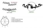
  The principle of operation of the motion sensor is as follows. Let's assume that the sensor is installed in an empty room. Each sensitive element receives a constant dose of radiation, which means that the voltage on them has a constant value (left figure).
  As soon as a person enters the room, he first enters the field of view of the first element, which leads to the appearance of a positive electrical impulse on it (central figure). A person moves, and his thermal radiation through the lenses hits the second PIR element, which generates a negative pulse. The electronic circuit of the motion sensor registers these multidirectional pulses and draws conclusions that a person has fallen into the field of view of the sensor. A positive pulse is generated at the output of the sensor (right figure).
 2. Setting up the HC-SR501
In this lesson, we will use the HC-SR501 module. This module is very common and is used in many DIY projects due to its low cost. The sensor has two variable resistors and a jumper for setting the mode. One of the potentiometers controls the sensitivity of the device. The larger it is, the further the sensor “sees”. Sensitivity also affects the size of the detected object. For example, you can exclude a dog or a cat from triggering. The second potentiometer adjusts the response time T
. If the sensor detects movement, it generates a positive pulse of length T
. Finally, the third control is a jumper that switches the sensor mode. Pregnant L
the sensor is counting T
from the very first operation. Let's say we want to control the light in the bathroom. Entering the room, a person will trigger the sensor, and the light will turn on exactly for a while T
. At the end of the period, the output signal will return to its original state, and the sensor will give the next trigger. Pregnant H
sensor starts timing T
every time after motion is detected. In other words, any human movement will reset the countdown timer. T
. By default, the jumper is in the state H
.
The second potentiometer adjusts the response time T
. If the sensor detects movement, it generates a positive pulse of length T
. Finally, the third control is a jumper that switches the sensor mode. Pregnant L
the sensor is counting T
from the very first operation. Let's say we want to control the light in the bathroom. Entering the room, a person will trigger the sensor, and the light will turn on exactly for a while T
. At the end of the period, the output signal will return to its original state, and the sensor will give the next trigger. Pregnant H
sensor starts timing T
every time after motion is detected. In other words, any human movement will reset the countdown timer. T
. By default, the jumper is in the state H
.
3. Connecting HC-SR501 to Arduino Uno
For connection to a microcontroller or directly to a relay, the HC-SR501 has three pins. We connect them to the Arduino as follows:| HC-SR501 | GND | VCC | OUT |
| Arduino Uno | GND | +5V | 2 |
 Layout appearance
 Program As already mentioned, the digital output of the HC-SR501 sensor generates a high signal level when triggered. Let's write a simple program that will send "1" to the serial port if the sensor saw movement, and "0" otherwise. const int movPin = 2 void setup() ( Serial.begin(9600); pinMode(movPin, INPUT); ) void loop()( int val = digitalRead(movPin); Serial.println(val); delay(100); ) We load the program on Arduino and check the operation of the sensor. You can tweak the sensor settings and see how it affects its operation.
 4. Light control based on motion sensor
The next step is the automatic lighting system. In order to control the lighting in the room, we need to add a relay to the circuit. We will use a relay module with protection based on optocoupler, which we already wrote about in one of the lessons (a lesson about relays). Attention! This circuit lights the lamp from a 220 volt network. It is recommended to check all connections seven times before connecting the circuit to the household power supply. circuit diagram Layout appearance
 Program Now let's write a program that, when the sensor is triggered, will turn on the relay, and therefore the lighting in the room. const int movPin = 2; const int relPin = 3; void setup() ( Serial.begin(9600); pinMode(movPin, INPUT); pinMode(relPin, OUTPUT); ) void loop()( int val = digitalRead(movPin); if (val) digitalWrite(relPin, HIGH) ; else digitalWrite(relPin, LOW); ) We load the program on Arduino, carefully connect the circuit to the household network and check the operation of the sensor. Conclusion Motion sensors are all around us. Thanks to security systems, they can be found in almost every room. As we found out, they are very easy to use and can be easily integrated into any Arduino or Raspberry Pi project. Here are a few situations and places where a motion sensor can come in handy:
 - automatic switching on of the light in the entrance of the house, in the bathroom and toilet, in front of the entrance door to the room;
- alarm indoors and outdoors;
- automatic door opening;
- automatic activation of the security camera.
In our imperfect world, various technical things are in great demand, designed to guard the property and peace of mind of citizens. Therefore, it is difficult, I believe, to find a person who would never see burglar alarms equipped with motion sensors. The physical principles of their operation, as well as the implementation may be different, but probably the most common are pyroelectric passive infrared sensors (PIR).
Approximately like this:

They react to changes in radiation in the infrared range, namely in its middle part - 5-15 microns (the body of an average healthy person emits in the range of about 9 microns). From the point of view of the end user, the thing is very simple - a power input (usually 12 volts) and a relay output (usually solid state and with normally closed contacts). Someone warm crept past - the relay worked. Boredom. But inside, things are not so simple.
Today we will devote a little time to theory, and then gut one such device and make it not just a sensor that reacts to the fact of movement, but registers the direction of movement.
Let's move on to practice
Armed with theoretical information, we get a soldering iron. The photo shows a disassembled sensor (the front cover with Fresnel lenses and the metal screen are removed).
We look at the marking of the microcircuit closest to the pyroelectric sensor (round metal with a window - this is it) and (oh, luck!) It turns out to be LM324 - a quad op-amp. By examining the surrounding elements, we find the output of the op-amp that is most likely suitable for our purposes (in my case, it turned out to be pin 1 of the microcircuit). Now it would be nice to check if we found it. Usually an oscilloscope is used for this. I didn't have it on hand. But it turned out to be an arduino. Since the signal level after amplification is on the order of a few volts, and we don’t need special measurement accuracy (a qualitative assessment is enough), then the Arduino ADC inputs are quite suitable. We solder the wires to the found output of the op-amp and the minus of the power supply and output it to the breadboard. Wires should not be long. Otherwise, there is a chance to measure not the sensor signal, but something completely different.
Now let's think about how fast you need to read the signal in order to get something sane. It was said above that the frequency range of the useful signal is limited to approximately 10 Hz. Recalling the theorem of Kotelnikov (or Nyquist - whichever you prefer), we can conclude that it makes no sense to measure a signal with a frequency above 20 Hz. Those. a sampling period of 50 ms is fine. We write a simple sketch that reads port A1 every 50 ms and dumps its value into the serial (strictly speaking, signal measurements occur less often than after 50 ms, since it also takes time to write to the port, but this is not important for our purposes).
unsigned long time; void setup() ( Serial.begin(9600); pinMode(A1, INPUT); time=millis(); ) void loop() ( if ((millis()-time) >= 50) ( Serial.println(analogRead (A1)); ) time=millis(); )
We turn it on and wave our hands in front of the sensor (you can run around, even more useful). On the computer side, we dump the data from the port into a file.
stty -F /dev/ttyUSB0 raw ispeed 9600 ospeed 9600 -ignpar cs8 -cstopb -echo cat /dev/ttyUSB0 > output.txt
We build a graph (a column with the numbering of readings has been added to the file):
gnuplot> plot "output.txt" using 1:2 with lines 
And we see what, in fact, we wanted - bipolar surges of voltage. Hooray, the theory works and the wire is soldered to the right place. A simple analysis (in other words, viewing) of the graph allows us to conclude that a more or less reliable fixation of the fact of the presence of movement can be considered a deviation of the signal by 150 units from the average value.
It's time to finally make a motion direction sensor.
Let's modify the schema. In addition to the analog sensor signal, we will connect a pair of LEDs to the arduino (ports 2 and 3, do not forget the current-limiting resistors) and write a slightly more complex sketch.
Expand
int a1; int state2=0; long average=0; intn=0; unsigned long time; void setup() ( pinMode(2, OUTPUT); pinMode(3, OUTPUT); pinMode(A1, INPUT); digitalWrite(2, LOW); digitalWrite(3, LOW); delay(30000); //my sensor after turn-on //it takes 30 seconds before starting work time=millis(); //we measure the signal a thousand times to //calculate its average value //so that there is something to count deviations from while (n<= 1000) {
++n;
a1=analogRead(A1);
average=average+a1;
delay(50);
}
average=average/1000;
//одновременным включением светодиодов
//сигнализируем, что система готова
digitalWrite(2, HIGH);
digitalWrite(3, HIGH);
delay(1000);
digitalWrite(2, LOW);
digitalWrite(3, LOW);
time=millis();
}
void loop() {
//опрашиваем датчик каждые 50 мс
if ((millis()-time) >= 50) ( //with this simple expression, the analog signal //turns into a discrete one with the values -1/0/1 a1=(analogRead(A1)-average)/150; //if there was a change in the signal polarity, then //turn on the desired LED switch (a1) ( case 1: if (state2=-1) (digitalWrite(2, HIGH); digitalWrite(3, LOW);) state2=a1; break; case -1: if (state2=1) (digitalWrite (2, LOW);digitalWrite(3, HIGH);) state2=a1; break; ) //repeat first time=millis(); ) )
In order to leave only one pair of the entire set of beams of the sensor's radiation pattern, we close all but one of the Fresnel lenses with a paper screen.

We enjoy the result.
The arduino motion sensor allows you to track the movement of objects that emit heat (people, animals) in a closed area. Such systems are often used in domestic conditions, for example, to turn on the lighting in the entrance. In this article, we will consider connecting PIR sensors in Arduino projects: passive infrared sensors or pyroelectric sensors that respond to movement. Small dimensions, low cost, ease of operation and no connection difficulties make it possible to use such sensors in various types of alarm systems.
The design of the PIR motion sensor is not very complicated - it consists of a pyroelectric element, which is highly sensitive (a cylindrical part with a crystal in the center) to the presence of a certain level of infrared radiation in the coverage area. The higher the temperature of the object, the greater the radiation. A hemisphere is installed on top of the PIR sensor, divided into several sections (lenses), each of which provides focusing of thermal energy radiation on different segments of the motion sensor. Most often, a Fresnel lens is used as a lens, which, due to the concentration of thermal radiation, allows you to expand the sensitivity range of the Arduino infrared motion sensor. 
PIR-sensor is structurally divided into two halves. This is due to the fact that it is the presence of movement in the sensitivity zone that is important for the alarm device, and not the level of radiation itself. Therefore, the parts are installed in such a way that when one more level of radiation is captured, the output will be a signal with a high or low value.
The main technical characteristics of the Arduino motion sensor are:
- The detection zone of moving objects is from 0 to 7 meters;
- Tracking angle range – 110°;
- Supply voltage - 4.5-6 V;
- Operating current - up to 0.05 mA;
- Temperature regime – from -20° to +50°С;
- Adjustable delay time from 0.3 to 18 s.
The module on which the infrared motion sensor is installed includes additional electrical wiring with fuses, resistors and capacitors.
The principle of operation of the motion sensor on the Arduino is as follows:
- When the device is installed in an empty room, the radiation dose received by each element is constant, as is the voltage;
- When a person appears in the room, he first of all enters the viewing area of the first element, on which a positive electrical impulse appears;
- When a person moves around the room, thermal radiation also moves with him, which hits the second sensor. This PIR element already generates a negative pulse;
- Multidirectional pulses are registered by the electronic circuit of the sensor, which concludes that there is a person in the field of view of the Pir-sensor Arduino.
 For reliable protection against external noise, temperature changes and humidity, the elements of the Pir sensor on the Arduino are installed in a sealed metal case. On the top of the case in the center is a rectangle made of a material that transmits infrared radiation (most often based on silicone). Sensing elements are installed behind the plate.
Wiring diagram for motion sensor to Arduino
 Connecting a Pir sensor to Arduino is not difficult. Most often, modules with motion sensors are equipped with three connectors on the back. The pinout of each device depends on the manufacturer, but most often there are corresponding inscriptions near the outputs. Therefore, before connecting the sensor to the Arduino, you need to familiarize yourself with the notation. One output goes to ground (GND), the second provides the required signal from the sensors (+5V), and the third is a digital output from which data is taken.
Pir sensor connection:
- "Earth" - on any of the Arduino GND connectors;
- Digital output - to any digital input or output of Arduino;
- Power supply - + 5V on Arduino.
The diagram for connecting an infrared sensor to Arduino is shown in the figure.
Program example
The sketch is a program code that helps to check the operation of the motion sensor after it is turned on. In its simplest example, there are many drawbacks:
- The probability of false positives, due to the fact that it takes one minute for the sensor to self-initialize;
- Lack of output devices of executive type - relays, sirens, light indications;
- A short time interval of the signal at the output of the sensor, which must be delayed at the software level in case of movement.
These shortcomings are eliminated by expanding the functionality of the sensor.
The simplest type of sketch, which can be used as an example of working with an Arduino motion sensor, looks like this:
#define PIN_PIR 2 #define PIN_LED 13 void setup() ( Serial.begin(9600); pinMode(PIN_PIR, INPUT); pinMode(PIN_LED, OUTPUT); ) void loop() ( int pirVal = digitalRead(PIN_PIR); Serial. println(digitalRead(PIN_PIR)); //If motion detected if (pirVal) ( digitalWrite(PIN_LED, HIGH); Serial.println("Motion detected"); delay(2000); ) else ( //Serial.print(" No motion"); digitalWrite(PIN_LED, LOW); ) )
Possible options for projects using a sensor
PIR sensors are indispensable in those projects where the main function of the signaling is to determine the presence or absence of a person within a certain workspace. For example, in places or situations such as:
- Turning on the light in the entrance or in front of the front door automatically, when a person appears in it;
- Turning on the lighting in the bathroom, toilet, corridor;
- An alarm is triggered when a person appears, both indoors and in the local area;
- Automatic connection of security cameras, which are often equipped with security systems.
Pir-sensors are easy to operate and do not cause difficulties when connecting, have a large sensitivity zone and can also be successfully integrated into any of the Arduino software projects. But it should be borne in mind that they do not have the technical ability to provide information about how many objects are in the coverage area, and how close they are to the sensor, and they can also work on pets.
PIR (passive infrared sensors) sensors allow you to capture movement. Very often used in alarm systems. These sensors are small in size, inexpensive, consume little energy, are easy to operate, and are practically not subject to wear. In addition to PIR, such sensors are called pyroelectric and infrared motion sensors.
There was a need to purchase a pair of sensors for domestic use in their crafts based on LED backlighting.
Since my consumption currents are relatively small, and the supply voltage is 12 V, compact pyroelectric infrared motion sensors in the case were purchased.
Package: 
I ordered two sensors with the ability to adjust the photosensitivity: 
Sensors support power from 12 to 24 volts. They already have soldered standard wires about 30 cm long with sockets for input and output, with a 2.1 mm center pin, and this is a big plus. No need to solder anything, just connect the power supply and use: 

The sensors themselves are quite compact. Appearance: 


Dimensions: 


To get to the board and adjustments, you need to open the case. Back cover on latches, pry off with a screwdriver: 


The pay looks like this: 
I found a diagram of this device, the ratings may differ, but in general, to understand the essence of the work, it is correct: 
Here we see a voltage regulator at the input to power the microcircuit: 
By the way, here is the datasheet of this element, it can be seen that different markings imply different stabilized output voltages. But the main point is that it supports an input voltage of up to 24 volts, which is why it should not be exceeded. 
Further, according to the scheme, there is a field effect transistor at the output, which is the key in the power-load circuit: 
The datasheet lists a maximum continuous current at normal room temperature of 15A, but since we don't have transistor cooling, we are limited in power output.
The heart of the device is the Biss0001 chip. This chip perceives an external radiation source and performs minimal signal processing to convert it from analog to digital form: 

A PIR motion sensor essentially consists of a pyroelectric sensing element (a cylindrical piece with a rectangular crystal in the center) that detects the level of infrared radiation. The sensor is actually divided into two parts. This is due to the fact that it is not the level of radiation that is important to us, but directly the presence of movement within its sensitivity zone. The two parts of the sensor are set up so that if one half picks up more radiation than the other, the output signal will generate a high or low value. 
Now directly to the adjustments. I set up the device, accordingly threw what and where to turn: 

The time is adjustable from 1 second to 500 seconds. When the slider is fully unscrewed, the light just blinks.
Regarding the threshold for turning on the sensor, I experimentally found that this voltage is from 11.5 Volts, if it is lower, then the sensor simply does not turn on: 
According to the diagram, it is clear that the output voltage from the sensor is less than or equal to the input. I set it to 12v. there is an error in the form of an inaccurate indication of the power supply, so the consumption of the sensor itself is of course lower: 
In standby mode, the sensor consumes 84 μA, and the output voltage is 170 mV. 
To be honest, setting up the sensor is very inconvenient with the board removed, so I made holes on the back cover, and it's much better like this: 
Gathered a schematic, set everything up: 
Checked:
The sensor has been working for two days now, I put the second one on the backlight of the headphone stand, and I like that, unlike the previous one, which worked from 220 V, was larger and clicked a relay, this one is more compact and, of course, silent.
I didn’t measure the maximum range, but in an apartment from 3 meters it definitely works
Am I happy with my purchase? A complete, high-quality finished device.
What we liked:
+ Fully customizable mode of operation
+ Minimum own consumption
+ Quality workmanship and compactness
+ Clarity of operation without gaps
+. Presence of wires with sockets
What did not like:
- Lack of direct access to the settings without parsing the case (solid)
- Mounting ears are very small (but it is better to mount on double-sided tape like 3M)
The white sensor cap protrudes from the black housing, but is black in the non-light sensor option.
That's all.