The topic of car chargers is interesting to a lot of people. From the article you will learn how to convert a computer power supply into a full-fledged charger for car batteries. It will be a pulse charger for batteries with a capacity of up to 120 Ah, that is, charging will be quite powerful.
You don’t need to assemble anything - just the power supply is being redone. Only one component will be added to it.
A computer power supply has multiple output voltages. The main power buses are 3.3, 5 and 12 V. Thus, the device will need a 12-volt bus (yellow wire) to operate the device.
To charge car batteries, the output voltage should be in the region of 14.5-15 V, therefore, 12 V from a computer power supply is clearly not enough. Therefore, the first step is to raise the voltage on the 12-volt bus to a level of 14.5-15 V.
Then, you need to assemble an adjustable current stabilizer or limiter so that you can set the required charge current.
The charger can be said to be automatic. The battery will be charged to the set voltage with a stable current. As the charge increases, the current will decrease, and at the very end of the process it will equal zero.
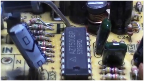
Starting to manufacture the device, you need to find a suitable power supply. For these purposes, suitable blocks in which there is a TL494 PWM controller or its full-fledged analogue K7500.
When the correct power supply is found, you need to check it. To start the unit, you need to connect the green wire to any of the black wires.
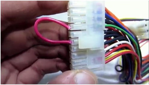
If the unit starts, you need to check the voltage on all tires. If everything is in order, then you need to remove the board from the tin case.
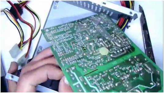
After removing the board, it is necessary to remove all wires, except for two black ones, two green ones and goes to start the unit. It is recommended to unsolder the remaining wires with a powerful soldering iron, for example, 100 watts.
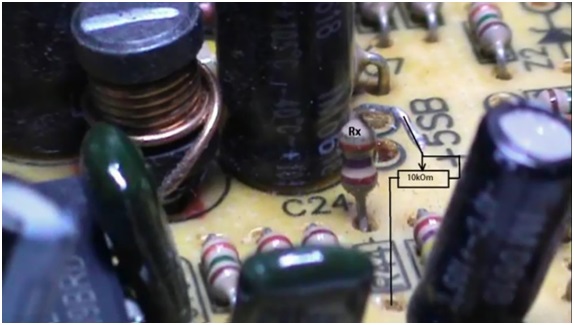
This step will require all of your attention, as this is the most important point in the whole rework. You need to find the first pin of the microcircuit (in the example, the microcircuit is 7500), and find the first resistor that is applied from this pin to the 12 V bus.
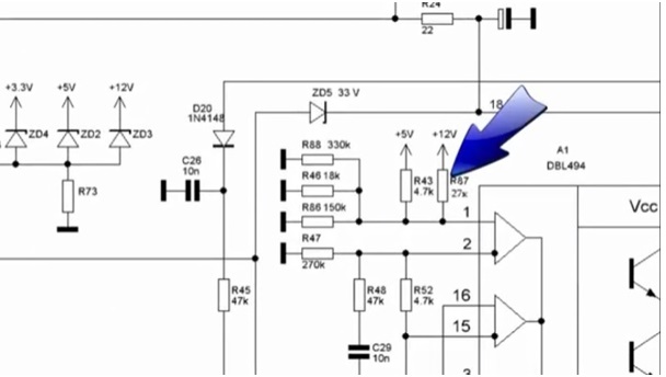
There are many resistors on the first output, but finding the right one is not difficult if you ring everything with a multimeter.
After finding the resistor (in the example it is 27 kOhm), it is necessary to unsolder only one output. In order not to get confused in the future, the resistor will be called Rx.
Now you need to find a variable resistor, say, 10 kOhm. Its power is not important. You need to connect 2 wires about 10 cm long each in this way:
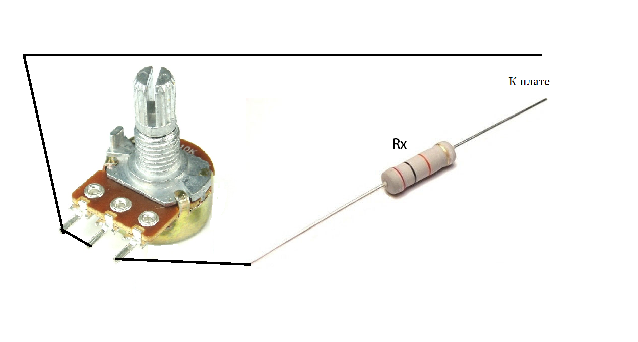
One of the wires must be connected to the soldered output of the Rx resistor, and the second one must be soldered to the board in the place where the output of the Rx resistor was soldered from. Thanks to this adjustable resistor, it will be possible to set the required output voltage.
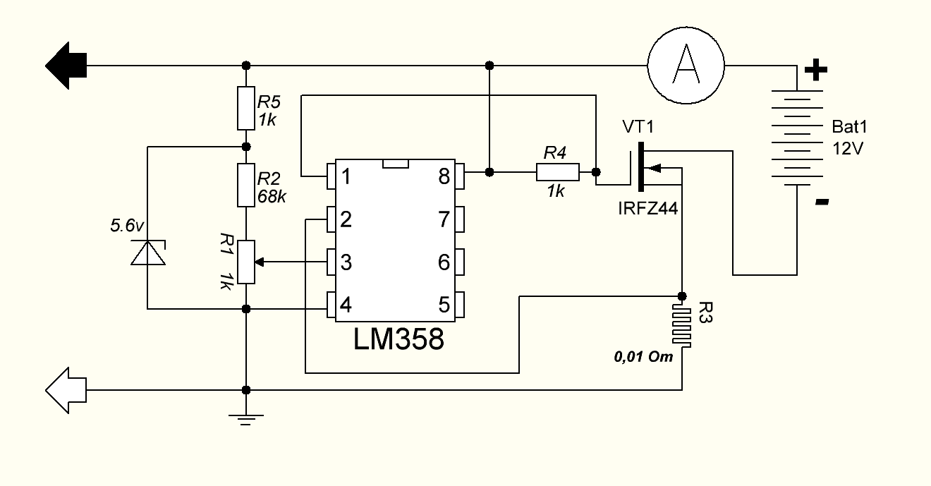
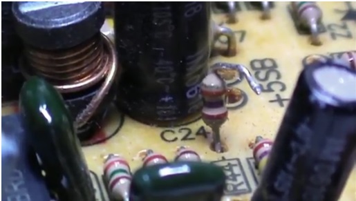
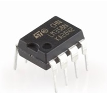
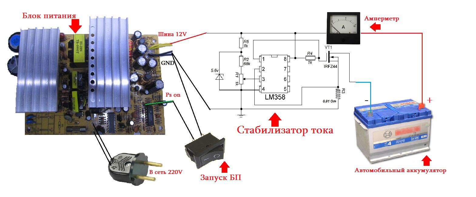
A stabilizer or charge current limiter is a very important addition that every charger should have. This node is made on the basis of an operational amplifier. Almost any "opamp" will do here. The example uses the budget LM358. There are two elements in the case of this microcircuit, but only one of them is needed.
A few words about the operation of the current limiter. This circuit uses an op amp as a comparator that compares the voltage across a low resistance resistor to a reference voltage. The latter is set using a zener diode. And the adjustable resistor now changes this voltage.
When the voltage value changes, the operational amplifier will try to smooth the voltage at the inputs and will do this by reducing or increasing the output voltage. Thus, the "opamp" will control the field effect transistor. The latter regulates the output load.
The field-effect transistor needs a powerful one, since all the charge current will pass through it. The example uses IRFZ44, although any other appropriate parameter can be used.
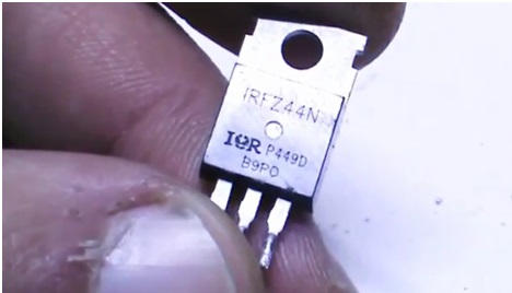
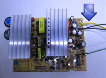
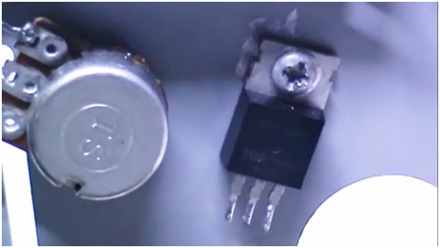
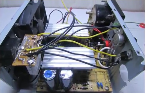
The transistor must be installed on a heat sink, because at high currents it will heat up well. In this example, the transistor is simply attached to the power supply case.
The printed circuit board was bred in haste but it worked out pretty well.
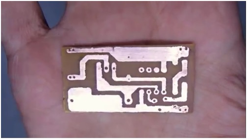
Now it remains to connect everything according to the picture and proceed with the installation.
The voltage is set in the region of 14.5 V. The voltage regulator can not be brought out. For control on the front panel, there is only a charge current regulator, and a voltmeter is also not needed, since the ammeter will show everything that needs to be seen when charging.
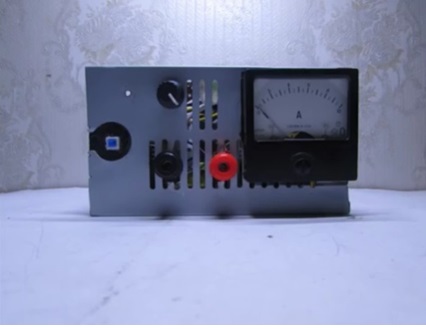
The ammeter can be taken Soviet analog or digital.
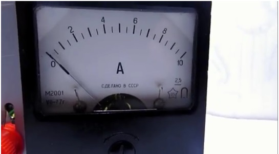
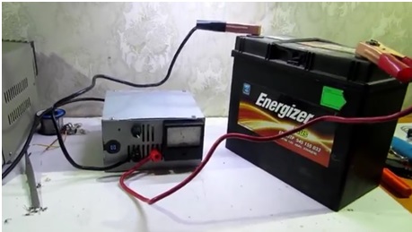
Also, a toggle switch for starting the device and output terminals was displayed on the front panel. Now the project can be considered completed.
It turned out to be an easy-to-make and inexpensive charger that you can safely repeat yourself.
Attached files: