Hyundai Accent is a fairly common car in a wide range of car owners. Over the years, the model has managed to take root on the streets of many cities. The older the car becomes and the less often technical inspections are carried out, the higher the likelihood that there will be problems with the electrics and appliances. In case of such malfunctions, the Hyundai Accent fuses and relays should be checked first. If the manual is not at hand, this article will help you.
List of fuses in the block under the hood
1 (100 A) - generator. If the battery began to discharge quickly, it is most likely the alternator and the lack of battery charge. Check this fuse, alternator belt tension, alternator connector pins, and wiring. There must be no short circuits in the car circuits. Check the voltage at the generator terminals with the car running (if there is no experience, it is better to contact an electrician).
If there is no voltage at the terminals, the brushes inside the generator may have worn out, in which case it can be repaired inexpensively. If squeaks or extraneous sounds are heard when turning the pulley, the bearings are most likely destroyed. In this case, it is better to replace the generator with a new one or send it in for repair.
2 (50 A) - door lock.(electric), brake lights, alarm, horn, heated rear window, interior lighting, electronic control unit (ECU).
If none of them work for you stop signal(including the cabin on the rear window), check this fuse first. If it is intact, then most likely the matter is in the “frog” (switch in the block above the brake pedal), connector or wiring.
If only one brake light does not light up, the lamp is most likely burned out. The lamps are double-filament, one thread for the size, the other for the stop. You can measure the voltage at the lamp connector with the brake pedal depressed, if it is there, it's in the lamp. If not, it's most likely wiring. See also the lamp connection diagram on the "Schemes" tab at the top of the page.
If it doesn't work" emergency gang“- check this fuse, fuses 1 and 7 in the passenger compartment and relay 10 in the passenger compartment, and then the power button and wiring.
If not working klaxon(beep), the case may be in this fuse, in the horn device itself, the wiring to it and the switch on the steering wheel. Try briefly applying 12V from the battery directly to the signal terminals. If no sound is heard, repair or replace it. This is a fairly common problem, especially in rainy weather. If there is sound, check the ground contact, it must be securely screwed. Wires should not have breaks and melted insulation.
If not working rear window heating, also check fuse 9 and relay 8 in the interior mounting block. If they are working, check the contacts of the heating elements on the rear pillar, as well as the threads on the glass for breaks.
Detected breaks can be repaired with a special conductive adhesive. You can check the voltage at the contacts of the heating elements, when the button is pressed, it should be there. If there is no voltage at the terminals, check the wiring laid along the body and the operation of the button.
3 (30 A) - head light and lamp dimensions. If the head light or dimensions lamps do not light up, also check fuses 27, 28, then in the passenger compartment relay 4, the lamps themselves, connector contacts, wiring and switch.
4 (20 A) - engine control unit. If the engine does not start, does not run smoothly or stalls for no apparent reason, check this fuse and its contacts, as well as fuses 5, 6, 16, 17, 18, 21, then fuse 5 and relay 3 in the passenger compartment. can be in the fuel system, gasoline pump, ignition system, candles and other components of systems. If there is no experience, it is better to conduct a complete engine diagnosis at.
5 (30 A) - engine start, ignition coils.
6 (20 A) - radiator fan. If the engine cooling fan does not turn on, also check relay 18 and fuse 10 in the passenger compartment. Try to apply 12 V voltage from the battery directly to the fan, thereby eliminating the possibility of its breakdown. It could also be a coolant temperature sensor (DTOZH) or a thermostat. Stop the engine immediately if you notice signs of overheating or overheating. Otherwise, you can end up with expensive repairs. If there is no experience, it is better to contact the workshop.
7 - connector.
8 - heater fan relay. If your stove has stopped working and it’s cold in the cabin, check this relay, as well as fuse 40. If the heater only works at maximum speed, check the resistor that controls the fan operation modes. If necessary, replace it with a new one. If the stove does not work in any of the modes, try applying 12 V directly from the battery to its motor.
To get to the motor, you need to remove the cover under the main glove box. If the motor does not work, it will need to be repaired or replaced with a new one. If you have the funds, it is better not to skimp and buy a new one. If the motor is running, check the wiring and the operation of the stove mode switch (along with its contacts).
9 - horn relay
10 (10 A) - interior lighting. If the light in the cabin does not light up, in addition, check fuse 2, the serviceability of the lamp and contacts in the ceiling, and the wiring. If the light does not come on only when the doors are opened, check the limit switches on the body that react to the opening and closing of the doors.
11 (10 A) - head unit of the audio system, radio. If the radio does not turn on, check this fuse, then remove it and check the contacts in the connectors on the back, as well as the fuse that is located directly on the wire (usually red). Wiring can also be the cause. Check where the power is supplied to the radio, from the ignition switch or directly from the battery. If 12 V voltage from the battery is applied directly to the necessary wires, the radio should turn on. If it does not turn on, it is most likely a malfunction inside it and it needs to be repaired or replaced.
12 - relay 2 of the fan of the heat exchanger of the condenser of the air conditioner. If the air conditioner stops working, check, in addition, fuses 13, 19, 20, 22, 32, as well as fuses 10 and 17 in the passenger compartment. If they are all OK, there may be no freon in the system and you need to refuel. It will not be superfluous to check the entire system and pipes for tightness and the absence of leaks. In winter, it is recommended to occasionally turn on the air conditioner so that it does not cause problems in the spring.
Look also at the compressor under the hood, when the mode is on, its clutch should spin. If it does not spin, either there is no freon, or one of the component systems is faulty.
13 - air conditioning compressor clutch relay. See previous paragraph.
14 - fog lamp relay. If none of the fog lights work, check, in addition, fuse 24, then fuse 10 and relay 2 in the passenger compartment. The front and rear PTFs are turned on with different buttons. Check the contacts and serviceability of the corresponding button on the dashboard, as well as the wiring. If only one “foglight” does not light up, check the voltage at its connector and, if present, replace the lamp.
15 - reserve.
16 (15 A) - idle speed controller (XX), camshaft position sensor (DPRV).
If the engine does not idle, does not start, stalls, or runs erratically, check this fuse, as well as the fuel system and fuel pump. The reason may be in addition to electrics in low-quality fuel, spark plugs, injectors and other components. If there is no experience, it is better to contact the diagnostic station.
17 (10 A) - engine control unit. See information about fuse 4.
18 - radiator fan relay. See information about fuse 6.
19 (10 A) - air conditioning. See information about fuse 12.
20 - relay 1 fan of the heat exchanger of the condenser of the air conditioning system. See 12.
21 (10 A) - engine control unit. See 4.
22 (10 A) - air conditioning compressor clutch. See 12.
23 (10 A) - sound signal. See 2.
24 (15 A) - fog lights. See 14.
25 (10 A) - headlight lamp on the right side.
26 (10 A) - headlight lamps on the left side. If both headlights are not working, see 3. If one headlight works and the other does not, check one of these fuses, as well as the serviceability of the lamp and contacts in its socket.
27 (10 A) - front and rear side light lamps on the right side.
28 (10 A) - front and rear side light lamps on the left side. If none of the indicator lamps are lit, see 3. If the lamps on only one side of the vehicle are not lit, check one of these fuses, the lamps and their connectors.
29 - lamp relay dimensions. See 3.
30 - generator pre-excitation resistor. See information about fuse 1.
31 - starter relay. If you turn the ignition key and the starter does not turn, check this fuse. If it is working, check the battery charge and the fastening of the terminals on it. They could oxidize or relax. Clean them inside with a sandpaper or a round file and fasten them well to the battery terminals. If after that the starter does not start to turn, check it by closing 2 contacts with a screwdriver or a metal object.
Before doing this, make sure the gearshift lever is in the neutral position. If the battery is charged and the starter does not work when the contacts are closed or 12 V is applied directly to it, most likely it is out of order. In this case, repair (replacing brushes or other worn parts) or buying a new one can help. If the starter only works with direct voltage, check the wiring and the ignition switch. Perhaps the tracks in the lock are oxidized or there is no contact in the connector.
32 (20 A) - fan of the heat exchanger of the condenser of the air conditioning system. See 12.
33 (30 A) - power windows. If none of the power windows work, in addition to this fuse, check relay 7 in the passenger compartment. If the power window does not work in one particular door, check the wires between the door and the body (they often break in this place), the control buttons on the door, and also the lift mechanism itself. To get to it, you need to remove the door trim. All cables must be in their grooves, the gears must be intact and the motor must work. Also check that there are no foreign objects in the mechanism.
34 (30 A) - ABS control unit. If the ABS system stops working on slippery surfaces and the wheels lock up when braking, check this fuse. If it is intact, it may be in the ABS unit, which is located under the air filter. The motor could fail in it or its brushes could wear out.
35 - low beam relay, permanently on. If both low beam headlights do not work, check this relay, as well as lamps and wiring. Both bulbs could burn out. If only one headlight does not light, check the lamp and the contacts in the connector. The lamps have 2 threads - one for the low beam, the other for the high beam.
36 - fuel pump relay. If the fuel pump stops working and the sound of its operation is not heard when the ignition is turned on, check this relay and the wiring in the cabin to the pump. The wires are usually laid under the driver's door sill and further along the body. Check that the wires are not damaged, melted or twisted.
If twists are found, they must be soldered securely. If you installed an alarm, then you may have installed an additional relay to block the fuel pump. In this case, check it too. This relay is usually located behind the small glove box. You can also apply 12 V to the fuel pump directly, thereby checking its performance.
37 (30 A) - ABS control unit. See 34.
38.39 - diode socket.
40 (30 A) - heater fan (stove). See 8.
Fuses in the cabin
The fuse box is located in the passenger compartment and is located below, at the left foot of the driver.
1 (10 A) - direction indicators. If the turn signals stop working and none of them light up, check, in addition to this fuse, also relay 10 in the passenger compartment and a relay installed separately under the steering wheel. If the relay is collapsible, you can remove the case and check the board for burnt tracks or blackened parts. Or replace it with a new one that is known to be good.
Then check the steering column switch, the health of the tracks and contacts in it, as well as the contacts in its connector and wiring. You should also check the lamps, which could burn out all at once. If only one turn signal does not work, most likely the problem is also in the lamp. Replace with a good one and check the contacts in the connector.
2 (10 A) - ABS, control lamps on the dashboard. If ABS does not work, see 34.
If the lamps on the panel do not work, check this fuse, the lamps themselves and the wiring.
3 (10 A) - devices on the panel. If your dashboard stops working, some of the devices work, and some don’t, most likely it’s the contacts on the panel board, or connectors. If this fuse is good, try to move the connectors on the back of the panel. Check the contacts in them and the wires. It may be necessary to remove and disassemble the entire panel to get to the boards inside it. The boards need to be inspected so that they do not have broken or burnt tracks and other visible traces of a short circuit, lack of contacts.
4 (15 A) - airbags. If at least one airbag has worked for you, then for the previous level of safety you will need to replace the deployed airbag module, the SRS control unit and the belts. The driver's pillow is located in the center of the steering wheel, the passenger one is above the glove compartment.
5 (10 A) - engine control unit, reversing lamps, automatic transmission control unit.
If you have engine problems, see fuse 4.
If the reverse lights do not light up when the gearbox is engaged in reverse gear, check the lamps themselves and their connectors, then the reverse gear switch, which is located on the gearbox in the upper part, and the wires coming from it. To get to it, you need to remove the battery and air filter. Through the received space, access to it will open. Replace with a new one or repair the old one if it fails.
The location of the reverse sensor on the gearbox
6 (10 A) - central locking, electric door lock. If only one door has stopped closing or opening, check the electric drive of the lock so that it is in good condition and does not jam, and there is also a sufficient amount of lubricant. The case can also be in the actuator (block with the board) or the relay inside it. The actuator is located in the door, looks like a small box. It supplies a short-term voltage of 12 V to electric locks of the required polarity (one polarity for opening the locks, the other for closing them).
Appearance of the door actuator block
7 (10 A) - alarm. If the “emergency gang” stops working, check, in addition, fuse 2, the correctness of the button and its contacts, wiring, and the lamps themselves.
8 (10 A) - brake lights. See information about fuse 2.
9 (20 A) - heated rear window. See 2.
10 (10 A) - power windows, headlight relay windings, headlight washer, air conditioning condenser heat exchanger fan, cooling radiator fan, fog lights (front and rear).
If the power windows do not work, see 33.
If the fog lights do not work, see 14.
If the radiator fan does not work, see 6.
11 (20 A) - windshield wiper and washer. If the “wipers” do not work, check, in addition to this fuse, relay 5. If they are serviceable, most likely it is the motor or the wiper mechanism. The motor is mounted on the rear wall of the engine compartment in the direction of travel on the right side, near the shock absorber strut.
You can disassemble the entire mechanism, the trapezoid, check the health of the motor by applying a voltage of 12 V to it, inspect all the rods and connections, clean and lubricate the rubbing and moving parts with WD or similar lubricants, then assemble the entire mechanism and re-check the operation of the wipers. If the wiper mechanism is old, then some parts could “stick”, in which case the best option would be to replace the entire trapezoid assembly. Its minimum price is in the range of 500-1000 rubles.
12 (10 A) - heated seats. If your seat heating stops working, check the contacts in the connector under the seat, as well as the wiring and the power button. Sometimes it can be the heating elements inside the seat, which could break off the wires.
13 (10 A) - ABS. See 34.
14 - reserve.
15 (15 A) - cigarette lighter. If the cigarette lighter stops working, check this fuse, the antennae inside the socket so that they do not close and are in place. If the fuse blows when the connector is inserted into the socket, most likely you are connecting a low-quality device, with a non-standard connector that closes or deforms the contacts. Also check the contacts and wires at the cigarette lighter socket under the panel. They should be 12 V.
16 (10 A) - electric mirrors. If one of the mirrors is no longer adjustable, it may be in the button or its contacts. Also check that there are no foreign objects or ice in the mirror mechanism. Try gently moving it with your hand. Check the wiring and connector, for this you need to remove the trim and the corner on the mirror.
The mechanism of the motors in the disassembled rear-view mirror
17 (10 A) - air conditioning. If the air conditioner does not work, see 12.
18 - reserve.
Relay in the cabin
The relay box is located in the passenger compartment behind the small glove box.
1 - relay of the electronic brake force distribution system EBD.
2 - rear fog lamp relay.
3 - the main relay of the engine management system.
4 - head light relay. See information on fuse 3.
5 - windshield wiper and washer relay. See information on fuse 11.
6 - ABS relay. See prev. 34.
7 - power windows relay. See prev. 33.
8 - rear window heating relay. See prev. 2.
9 - horn relay. See prev. 2.
10 - relay direction indicators, alarm. See prev. 1.
Connection diagrams
Diagram of wiring harnesses laid along the body
 |
Wiring diagram for brake lights
Hyundai Accent fuses and relays in the heating, ventilation and air conditioning system

1 - power supply +12 V
2 - +12 V power supply, the main engine control relay is on
3 - +12 V power supply, ignition on
4 - fuse box and relay (engine compartment)
5 - cabin fuse box
6 - stove fan fuse
7 - air conditioning compressor clutch fuse
8 - fuse for power windows, relay windings for headlights, headlight washer, air conditioning condenser heat exchanger fan, radiator fan, front and rear fog lights
9 - stove fan relay
10 - connector
11 - to the headlight washer relay
12 - air conditioning compressor clutch relay
13 - connector
14 - to the cabin relay unit
15 - automatic transmission control unit
16 - cabin fuse box
17 - air conditioner fuse
18 - stove fan motor
19 - engine control unit (ECU)
20 - from the block on the dashboard wiring harness
21 - stove fan motor resistor (heater operating modes)
22 - pressure switch
23 - air conditioner switch
24 - air conditioning compressor clutch
25 - from the block on the dashboard wiring harness
26 - stove speed switch (heater fan operation modes)
27 - thermal switch
28, 29 - to the block on the dashboard wiring harness
A free collection of color schemes in Russian for the electrical equipment of a Hyundai Accent (1.5i) car since 2000. It shows the relay and fuse box, as well as some other modules. Continuation of the catalog of schemes. Fuses are used to break the circuit when the current reaches a certain value, in order to protect elements and wires that can be damaged by too much current. A sudden increase in current is usually caused by a fault in the circuit, most often a short circuit. The designations of the circuits protected by fuses are indicated on the cover of the fuse box.
Before removing a fuse, turn off the corresponding circuit, then remove the fuse from the contacts. A wire should be visible inside the fuse; if the fuse is blown, the wire will be broken or melted. Always use fuses of the required capacity. Never use a fuse of a different capacity and do not replace it with something else. Do not replace the fuse more than once without correcting the source of the problem. The current protected by the fuse is indicated on the top of the fuse: note that the fuses have different colors for easy identification. If a fuse blows immediately after replacement, do not replace it again until the cause of the problem has been identified and corrected. In most cases, the fault is caused by a short circuit caused by poor insulation. If the fuse is protecting multiple circuits, try to find the circuit that is causing the fuse to blow, including each circuit in turn (if possible). Always have a set of spare fuses of different ratings in your car. They must be fixed at the base of the fuse box.
If you think the connection is not good, disassemble the connection and clean to bare metal the contact surface and the wire terminal or the surface of the grounding element. Remove all dirt and corrosion, then use a knife to remove a layer of paint in order to obtain a reliable metal-to-metal bond. When assembling, fix the connection securely; When installing the wire terminal, use toothed washers between the terminal and the body. After connection, apply a layer of Vaseline or silicone grease to the connection to prevent corrosion.
Fuses and relays HYUNDAI ACCENT
Mounting block for relays and fuses in the engine compartment
1 - fuse 100 A of the generator circuit; 2 - 50 A integrated fuse (circuits for the electric door lock, alarm, brake signals, rear window heating, horn, interior lighting lamp, ECU); 3 - fuse 30 A of the head and side light lamp circuit; 4 - 20 A fuse for the engine control unit circuit; 5 - 30 A fuse for starting the engine and ignition coils. 6 - 20 Amp fuse for the radiator fan circuit of the engine cooling system, 7 - wiring connector, 8 - heater fan relay. 9 - horn relay, 10 - 10 A fuse for Hyundai Accent interior lighting lamp circuit. 11 - 10 A fuse for the circuit of the head unit of the sound reproduction system. 12 - relay 2 of the air conditioning condenser heat exchanger fan, 13 - air conditioning compressor clutch relay, 14 - fog lamp relay socket; 15 - reserve fuse socket; 16 - fuse 15 A idle speed controller and camshaft position sensor. 17 - 10 A fuse for the engine control unit circuit. 18 - radiator fan relay of the engine cooling system; 19 - fuse 10 A for the air conditioning circuit; 20 - relay 1 of the fan of the heat exchanger of the condenser of the air conditioning system; 21 - 10 A fuse for the engine control unit circuit, 22 - 10 A fuse for the air conditioning compressor clutch circuit, 23 - 10 A fuse for the horn circuit; 24 - 15 A fuse for the fog lamp circuit. 25 - 10 A fuse for the right headlight lamp circuit. 26 - fuse 10 A of the circuit of the left head light lamp; 27 - fuse 10 A of the side light lamp circuit of the starboard side of the car; 28 - fuse 10 A of the side light lamp circuit of the left side of the car; 29 - relay lamps side light; 30 - generator pre-excitation resistor; 31 - Hyundai Accent starter relay, 32 - 20 A fuse for the condenser heat exchanger fan circuit, 33 - 30 A fuse for the power window circuit. 34 - 30 A fuse for the ABS control unit circuit; 35 - relay socket for constantly on low beam; 36 - fuel pump relay; 37 - 30 A fuse for the ABS control unit circuit; 38.39 - diode socket; 40 - 30 amp fuse for heater fan circuit.
Relay box in the passenger compartment


Hyundai fuse box


Location of wiring harnesses in Hyundai Accent


Car electrical diagrams
Power supply module


Earth connection diagram


Hyundai Accent Engine Start Wiring Diagram

Wiring diagram for generator and cooling system

Vehicle engine management system


Wiring diagrams of the Hyundai Accent car - a collection of color schemes in Russian for the electrical equipment of the Hyundai Accent car since 2000. shows the relay and fuse box, as well as some other modules.
Scheme of the ignition system and determining the speed of the car
Automatic transmission control circuit
Hyundai Accent


Scheme for switching on the automatic transmission lock

ABS wiring diagram
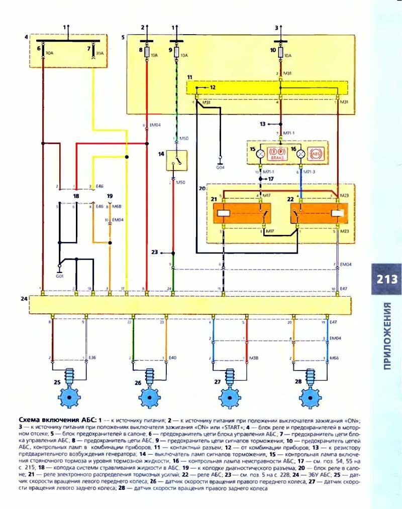
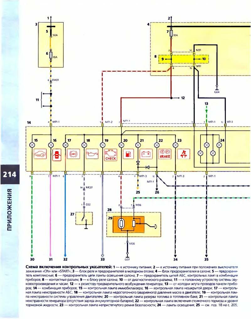
Connecting control pointers
Hyundai Accent

Block of cleaners and washers of a windshield

Scheme of blocking of the electric drive of doors

Power windows Hyundai Accent


Scheme of the electric drive of mirrors and heating unit

Turning on outdoor lighting - circuit diagram

Car headlight dimmer - wiring diagram

Audio System Diagram Accent

Scheme electrical sound signal (klaxon)

Direction and alarm indicators - connection

Clearance light and number plate lamps
Hyundai Accent

Rear lights and fog lights

Braking and reversing lamps - connection in the diagram

Illumination of the trunk and car interior


Symbols on electrical diagrams
Symbols on electrical diagrams
1...Battery
2 ... Ignition switch (lock)
3...Hyundai Accent starter
4...Generator
5... Fuse box under the hood
6... Front panel fuse/relay/multi-timer box
7... Horn button/headlight switch
a - starter switch
b - marker lights / headlights
c - front fog lights
d - flashing headlights
8... Cooling fan switch
9...Cooling fan motor
10...Cooling fan resistor
11...Diagnostic connector
12...Relay box under the hood
a - Hyundai Accent starter relay
b - injection system relay
c - cooling fan relay
d - relay low speed cooling fan
e - power steering relay
f - fuel filter heating relay
g - atmospheric pressure switch
15...Electric power steering pump
16...Security control unit
17 ... Passenger seat belt pretensioner
19...Driver airbag
20...Passenger airbag
21... Horn button/headlight switch
a - sound signal
b - marker lights / headlights
d - rear fog lights
e - direction indicator
22... Horn
23... Cigarette lighter
25 ... Heater fan assembly
26 ... Heater fan switch
a - Hyundai Accent switch
b - air conditioner switch
c - circulation switch
d - rear window heating switch
e - rear window heating indicator
f - recirculation indicator
g - air conditioner indicator
27 ... Interior lighting rheostat
30 ... Air conditioning control unit
31...Three-function air conditioner switch
32 ... Air conditioning clutch
35...Dashboard
a - fuel gauge
b - immobilizer indicator
c - injection system indicator
d - battery emergency charging indicator
e - fuel reserve indicator
f - emergency temperature indicator
g - indicator of emergency oil pressure drop
h - rear fog lamp indicator
i - fog lamp indicator
j - right turn indicator
k - left turn indicator
l - low beam indicator
m - high beam indicator
n - seat belt indicator
r - open door indicator
s - instrument lighting
t - temperature indicator
u - brake pad wear indicator
v - ABS indicator
w - brake system malfunction indicator
x - tachometer
y - speedometer Hyundai Accent
z - oil level indicator
a1 - on-board computer
36 ... Fuel pump / fuel level sensor unit
37 ... Emergency oil pressure drop sensor
38 ... Seat belt sensor
39 ... Temperature sensor / emergency increase in coolant temperature
40 ... Pad wear sensor
41 ... Sensor for emergency drop in brake fluid level
42 ... Parking brake lever position sensor
43... Oil level sensor
44 ... Wiper / washer switch
a - on-board computer reset button
b - windshield wiper
c - rear window wiper/washer
d - windshield washer
46...ABS control unit
47 ... Left front wheel sensor
48 ... Right front wheel sensor
49 ... Left rear wheel sensor
50 ... Right rear wheel sensor
51...Clock/outside temperature gauge (depending on equipment level)
52...Clock/outside temperature gauge/audio display (depending on equipment level)
53 ... Passenger side exterior mirror assembly (outside air temperature sensor)
54 ... Left marker lights
55... Right marker lights
56 ... Left headlight
57...Right headlight
58 ... Left rear light
a - tail light
b - reversing lamps
c - brake lights Hyundai Accent
d - direction indicators
e - fog lights
59...Right rear light
a - tail light
b - reversing lamps
c - brake lights
d - direction indicators
60...License plate lighting
61 ... Left front fog lamp
62...Right front fog lamp
65...Upper brake light
66 ... Reversing light switch (manual transmission)
67... Automatic transmission module
68 ... Automatic transmission control unit
69 ... Stoplight switch
70 ... Left turn signal
71 ... Right turn signal
72 ... Side repeater of the left direction indicator
73 ... Side repeater of the right direction indicator
74... Alarm switch
75 ... Headlight range control
76 ... Motor of the left headlight corrector
77 ... Right headlight corrector motor
80...Infrared receiver (if provided)
81 ... Luggage compartment lighting
82 ... Luggage compartment lighting switch
83... Front "polite" lighting
84 ... Switch in the driver's door
85 ... Switch in the passenger door
86 ... Switch in the left rear door
87 ... Switch in the right rear door
88 ... Windshield wiper motor
89 ... Rear window wiper motor
91 ... Windshield washer pump
92 ... Headlight washer pump relay
93 ... Rear window heater.


