The use of the bolted method of connecting parts allows, if necessary, to disassemble the structure or mechanism and simplifies dismantling for repair or restoration work.
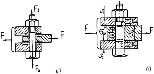
During operation of the structure, the connections of parts are tested different kinds loads to be taken into account in the design. Bolted connections can be subjected to loads directed along the bolt axes (tension-compression), radial (torsion), as well as loads directed in a plane perpendicular to the bolt axis. The latter, overcoming the friction force provided by tightening the bolt-nut pair, are capable of causing shear and shear deformation of the fastener (rivets, studs, pins, keys, etc. are also affected by such forces).
By using bolted connection it is possible to provide fastening of several parts, which increases the number of possible cutting planes, which is also necessarily taken into account when designing a structure.
When deriving, some simplifications are allowed when depicting the impacts experienced by the parts, and the values of the acting forces are taken as maximum to ensure reliability.
CALCULATION FORMULA FOR JOINTS EXPERIENCED LOADS ON SHEAR
Shear bolt design takes into account several factors that affect the ability of the connection to resist the forces acting on the parts to be joined. These factors become:
- roughness of parts;
- yield strength of materials;
- the difference between the diameters of the hole in the part and the bolt shaft;
- connection tightening force;
- transverse dimensions of the parts to be joined (thickness);
- the location of the holes relative to each other and the edges of the parts to be joined;
- bolt shaft diameter in its working part. The outer diameter of the thread is not taken into account, since it does not resist external forces;
- coefficients of friction of the materials from which the parts to be joined are made.
Depending on the various conditions connections, shear calculations are made according to different formulas.
Preloaded bolt diameter (without clearance) , is calculated per slice by the formula:
D = √4P/πt
D is the bolt diameter;
P is the transverse force acting on the bolt (in newtons);
t is the allowable shear stress (in MPa), which depends on the material and is set according to reference tables, usually 0.2-0.3 of the yield strength.
To prevent shearing of bolts installed with clearance , it is necessary to ensure the proper friction force between the parts, which is achieved by a certain tightening force of the bolts, and is calculated using the following formula:
Q=P/f
P is the force transverse to the shear (shear) force, created by tightening the bolt-nut pair;
f is the coefficient of friction. Depends on the materials from which the parts to be joined are made, on the cleanliness of the processing of the mating surfaces and the presence of lubrication, it is set according to reference books.
Also tightening force
can be calculated using the formula:
Q = πd²q/4
d is the inner diameter of the bolt thread;
q is the maximum allowable tensile stress, MPa.
For multiple joints
the bolt is calculated for the tightening force:
Q = P/fi
fi is the number of joints.
Tapered bolts are calculated in the same way as those installed with an interference fit, since the conical shape of the bolt head ensures mating with the part without clearance.
When calculating a connection that has several points of attachment of parts, the total load should be evenly distributed between the fasteners, or for the least loaded sections, the maximum values of shear forces should be taken.
Of course, the above formulas are of a general nature, not taking into account all the operating conditions of the connection. The previously considered factors affecting the strength of the joint are introduced, if necessary, into these formulas in the form of additional coefficients obtained by calculation or experience.
Moreover, when fastening parts with bolts, it is necessary to take into account the fact that different parts of the connection will be affected by forces that are not the same in absolute value and direction. To ensure the strength of the structure, the connection should be made taking into account the stress diagram, especially in cases not provided for by the standards.
Standards for bolted connections, developed taking into account the requirements for strength and reliability, establish the steel grades used for the manufacture of fasteners, dimensions fasteners and the distance between them. In addition, for bolts installed with a gap, the dimensions of the holes for them are regulated.
So, for example, the requirements for those used in construction are established by the industry standard STO 0041-2004 “Building steel structures. Bolted connections. Design and calculation.
Standards cover a wide range of sizes fasteners- bolts, nuts, lock washers, which allows you to design structures without resorting to unnecessary calculations of new parts and their production. It is enough to use the ones already produced by the industry, making adjustments taking into account the margin of safety (as a rule, its coefficient is taken equal to 1.3 of maximum load per connection).
DISPLAY OF BOLTED JOINTS ON DRAWINGS
When constructing threaded (including bolted) connections in the drawings, the screw thread is depicted conditionally. This achieves simplicity and speed of execution of drawings. Accepted conditional images are set in accordance with GOST 2.315-68.
The outer thread of the bolt along the outer diameter is conventionally indicated by a solid main line, along the inner diameter - by a solid thin line. On the projections of the bolt, formed by dissecting it with a plane perpendicular to the axis, the inner diameter is indicated by a thin line drawn on three quarters of the circle. In this case, the chamfer is not depicted, only on the longitudinal section of the bolt. The distance between the thin and main lines should not be more than the thread pitch, but should not be less than 0.8 mm.
The internal thread on the nut is depicted in reverse - the main line along the inner diameter.
Hatching in sections and cuts is performed up to a solid main line. When applied to the drawing of a bolted connection, the dimensions of the bolt, nut and washer are made in accordance with their standard sizes. That is, the dimensions of standard fasteners are set according to GOST on them.
Strength calculation threaded connections
Axial load of the screw is transmitted through the thread to the nut and is balanced by the reaction of its support. Each of Z threads are loaded by forces F1 , F2 , … F Z .
IN general case the loads on the coils are not the same. The problem of load distribution over the coils is statically indeterminate and was solved by the Russian scientist N.E. Zhukovsky in 1902 based on a system of equations for a standard hex nut. The graph shows a significant overload of the lower turns and the pointlessness of increasing the length of the nut, because. the last turns are practically not loaded. This load distribution was later confirmed experimentally. In calculations, uneven loading is taken into account by the empirical (experimental) coefficient Km , which is equal to 0,87 for triangular, 0,5 - for rectangular and 0,65 for trapezoidal thread.
The main types of destruction in fastening threads are the cut of the turns, in the running ones - the wear of the turns. Therefore, the main performance criterion
for the calculation of fastening threads - strength for shear shear stresses, and for lead threads - wear resistance for shear stresses.
Shear strength condition:
f/(π d 1 HKK m ) ≤[τ ] for screw; τ =f/ (π dHKK m ) ≤[τ ] for nut
Where H - the height of the nut or the depth of the screw into the workpiece, K =ab/p or K =ce/p – thread completeness factor, Km - coefficient of uneven load on the coils.
The condition of wear resistance to crushing:
s cm =f/ (π d 2 HZ ) ≤[ s]cm ,
Where Z - the number of working turns.
The equal strength of the thread and the screw shaft is the most important condition for assigning the height of standard nuts. So, taking the yield strength of the material as the ultimate stresses and taking into account that τ T ≈ 0,6 s T the condition of equal strength of the thread in shear and the screw shaft in tension will appear in the form: τ =f/ (π d 1 HKK m )= =0.6σ T =0.6F/ [(π/4) d 1 2 ]. At K = 0,87 And Km = 0,6 we get H ≈0,8 d1 , and given that d1 = d finally accept the height of the normal standard fastening nut H ≈0,8 d.
In addition to the normal standard, high H ≈1.2d and low H ≈0.5d nuts. For the same reasons, the depth of screwing screws and studs into parts is set: into steel H1 =d , in fragile - cast iron and silumin H =1.5d. Standard nut heights (except for low ones) and screwing depths save us from calculating the thread strength of standard fasteners.
In calculations, it is impossible to ignore the flexibility of the bolt and the parts to be joined. In the simplest case, with bolts of constant cross section and homogeneous parts
λ b = l b /(E b A b ) ; λ d = δ d / (E d A d ) ,
Where λ b , λ d - compliance of the bolt and parts, equal to their deformation under a single load (compliance is inverse to stiffness); E b , E d , A b , A d - moduli of elasticity and cross-sectional area of the bolt and parts; δ d - total thickness of parts δ d ≈ l b .
In a complex case, the flexibility of the system is determined as the sum of the flexibility of individual sections of the bolt and individual parts. Sectional areas A are understood to mean the areas of those parts that are subject to deformation from tightening the bolt. It is assumed here that deformations from the nut and bolt head are located deep into the parts along cones with an angle α =30 about . Equating the volume of these cones to the volume of the cylinder, find its diameter
D1=D +(δ1 +δ2 )/ 4; A d = π (D 1 2 –d resp 2 )/ 4.
deforms not only the bolt, but also gaskets, washers, Belleville springs, etc. (1,2). Therefore, when calculating the total bolt load F introduce the concept of external load factor χ equal to the bolt load increment in fractions of the external load. ThenF =F +χF . In this case, the elastic gaskets 1 and 2 cannot be considered as parts 3, 4 and 5, the deformation of which is reduced. In such cases, all connection details are divided into two systems:
1. Details of the bolt system, in which the absolute deformation increases under the action of the load (bolt, gaskets 1.2);
2. Parts of the hull system in which the absolute deformation is reduced (3,4,5).
Wherein 
In such connections, sets of elastic gaskets (washers, Belleville springs) significantly increase the compliance of the bolt system and, consequently, reduce the load on the bolt.
In the calculation of bolts, the force per bolt is first found. Then the whole variety of threaded joint arrangements can be reduced to three simple design schemes.
A. The bolt is inserted into the holes with clearance.
Connection loaded with longitudinal force Q . The bolt is stretched.
The tensile strength condition is written as: ![]()
Tensile stresses in the thread ![]()
From the condition of tensile strength, we find the inner diameter of the bolt thread ![]()
The found inner diameter of the thread is rounded up to the nearest larger in accordance with GOST 9150-59. There is also a specific size-number ( outside diameter threads) of the bolt.
B. The bolt is inserted into the holes without clearance.
R .
In this case, the bolt works on a shear. The inner diameter of the thread is calculated in the same way as in the tension case: ![]()
The procedure for assigning a bolt number is also similar to the previous case.
B. Bolt inserted with clearance.
Connection loaded with transverse force F .
Bolt tightening force V should give such a friction force between the parts that would be greater than the transverse shear force F .
The bolt works in tension, and from the moment of tightening it also experiences torsion, which is taken into account by the increase normal stresses on 30% (V 1,3 times).
According to the experience of numerous calculations, the value of the required tensile force is taken V depending on shear shear force F
V = 1.2 F/f.
Then the internal thread diameter of the bolt ![]()
Where f is the coefficient of friction.
In all cases, the calculation is the inner diameter of the thread, and the thread is indicated by the outer diameter. A common mistake is to calculate, for example, the inner thread diameter of a bolt 8mm , designate a bolt M8 , while the bolt should be assigned M10 , having an outer thread diameter 10mm , and internal 8mm .
The stress concentration in the cavities of the thread turns is taken into account by underestimating the allowable thread stresses by 40% compared to the corresponding allowable stresses of the material.
Types of destruction of threaded fasteners: rupture of the rod along the thread or transitional section at the head; damage or destruction of the thread (collapse and wear, shear, bend); damage to the head of the bolt (screw).
The dimensions of standard bolts, screws and studs meet the condition of equal strength of all connection elements. Therefore, one can limit oneself to the calculation according to one, the main criterion - the strength of the threaded part, and take the sizes of screws, bolts and nuts according to the tables of the standard, depending on the calculated thread diameter. The length of the bolt, screw and stud is selected depending on the thickness of the parts to be joined.
Consider the calculation of the strength of threaded connections under constant load.
The bolt is loaded with an external force F (bolt without pre-tightening), for example, a threaded section of a hook for hanging a load. Dangerous is the section of the hook, weakened by cutting (Fig. 26.21). From the tensile strength condition
![]() (26.22)
(26.22)
 (26.23)
where =0.6 is the allowable tensile stress of a carbon steel bolt.
The bolt is tightened with the tightening force Fc, and there is no external load (unloaded covers, brackets, etc.). The shank of the bolt experiences the combined action of tension and torsion, i.e. stretched by the axial force F 3 from tightening the bolt and twisted by a moment equal to the moment of friction forces in the thread T p (formula (26.16)), The strength of such bolts (Fig. 26.22) is determined by the equivalent stress
![]() (26.24)
(26.24)
where is the tensile stress, determined by the formula (26.22) at F=F s; - torsional stress, ![]() - the required safety factor of the bolt, taken depending on the material
- the required safety factor of the bolt, taken depending on the material
bolt, the nature of the load and the diameter of the bolt.
For standard metric threads, i.e., the calculation of the bolt for the combined action of tension and torsion can be replaced by the calculation for tension, but at a force F p increased by 1.3 times. For metric threads
 (26.25)
The design diameter of the thread of the bolt is determined by the formula (26.23), taking
The bolted connection is loaded with forces that shift the parts at the joint. The condition for the reliability of the connection is the absence of shift of the parts in the joint.
In connection with the gap (Fig. 26.23 a), the bolt is installed with pre-tightening. The external force F is not directly transferred to the bolt, so it is calculated for tension along
tightening force F c.
Rice. 26.23
In order to avoid shear of parts in the presence of a gap, the friction force on the joint surfaces must be not less than the external shear force F:
![]() (26.26)
(26.26)
Where i- the number of joints in the connection; f- coefficient of friction; K– safety factor ( TO= 1.3 – 1.5 at static and TO== 1.8 - 2.0 with variable load); Z is the number of bolts in the connection.
The bolt in this case is calculated by the tightening force
 (26.27)
When installing a bolt without a gap (Fig. 26.23 b), pre-tightening is not required. The bolt is sheared and buckled. Bolt shank count on
cut, and with thin details - and crushing. Strength conditions:
![]() (26.28)
(26.28)
where - respectively, the design and allowable stresses for the bolt material for shear, = (0.2 - 0.3); d o is the diameter of the uncut part of the bolt; - respectively, the calculated and the lowest allowable collapse stress (for the material of the bolt or part), = (0.8 - 1.0) ; S– smallest part thickness.
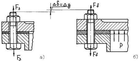
The bolt is tightened, and the external load tends to open the joint (bolts for fastening the covers of gas and liquid tanks loaded with pressure above atmospheric pressure, fastening cylinders, pumps, frames to foundations, etc.). The tightening of the bolts must ensure the tightness of the joint or the non-opening of the joint (to prevent the appearance of a gap) under load. This problem is solved taking into account the deformation of the connection parts.
An external load (R is the resultant load; Z is the number of bolts) causes the bolt to elongate by (Fig. 26.24), and the deformation of the parts decreases by the same amount. The load from the parts on the bolt will also decrease. That is why it is believed that the bolt perceives part of the external load.
where is the external load coefficient, showing what part of the external load is perceived by the bolt (takes into account the compliance of the bolt and the parts to be connected).
The value is determined by the condition of equality of additional deformations of the bolt and parts. From the condition of maintaining the density of the joint of the parts to be joined (the impossibility of forming a gap), take
![]() (26.31)
(26.31)
where K z is the preload safety factor: at a constant load K z = 1.25 - 2.0; with variable Kz = 2.5 – 4.
When calculating the strength, if subsequent tightening of the bolt is possible, it is calculated according to the design load F p, taking into account torsion: ![]() (26.32)
(26.32)
Dimensions are given for wheels with external teeth.