External characteristics of the welding arc power sources
The external characteristic of power sources (welding transformer, rectifier and generator) is the dependence of the voltage at the output terminals on the magnitude of the load current. The relationship between the voltage and current of the arc in steady state (static) mode is called the current-voltage characteristic of the arc.
The external characteristics of the welding generators shown in fig. 1 (curves 1 and 2) are falling. The length of the arc is related to its voltage: the longer the welding arc, the higher the voltage. With the same voltage drop (change in arc length), the change in welding current is not the same with different external characteristics of the source. The steeper the characteristic, the less influence the length of the welding arc has on the welding current. When the voltage changes by the value δ with a steeply falling characteristic, the change in current is equal to a1, with a gently falling characteristic - a2.
To ensure stable arc burning, it is necessary that the characteristic of the welding arc intersect with the characteristic of the power source (Fig. 2).
At the moment of ignition of the arc (Fig. 2, a), the voltage drops along the curve from point 1 to point 2 - until it intersects with the generator characteristic, i.e., to the position when the electrode is removed from the surface of the base metal. When the arc is extended to 3 - 5 mm, the voltage increases along curve 2-3 (at point 3, the arc burns steadily). Usually, the short-circuit current exceeds the operating current, but not more than 1.5 times. The voltage recovery time after a short circuit to the arc voltage should not exceed 0.05 s, this value evaluates the dynamic properties of the source.
On fig. 2.6 shows the falling characteristics 1 and 2 of the power source with a hard arc characteristic 3, the most acceptable for manual arc welding.
The open-circuit voltage (no load in the welding circuit) with decreasing external characteristics is always greater than the operating voltage of the arc, which greatly facilitates the initial and re-ignition of the arc. The open-circuit voltage must not exceed 75 V at a rated operating voltage of 30 V (increasing the voltage makes it easier to start the arc, but at the same time increases the risk of electric shock to the welder). For direct current, the ignition voltage must be at least 30 - 35 V, and for alternating current 50 - 55 V. According to GOST 7012 -77E for transformers rated for a welding current of 2000 A, the open circuit voltage should not exceed 80 V.
Increasing the open-circuit voltage of the AC source leads to a decrease in the cosine "phi". In other words, increasing the open-circuit voltage reduces the efficiency of the power supply.
The power source for manual arc welding with a consumable electrode and automatic submerged arc welding must have a falling external characteristic. A rigid characteristic of power sources (Fig. 1, curve 3) is necessary when welding in shielding gases (argon, carbon dioxide, helium) and some types of flux-cored wires, for example, SP-2. For welding in shielding gases, power sources with gently increasing external characteristics are also used (Fig. 1, curve 4).
The relative duration of work (PR) and the relative duration of inclusion (PV) in intermittent mode characterize the intermittent operation of the power source.
The value of PR is defined as the ratio of the duration of the working period of the power source to the duration of the full cycle of work and is expressed as a percentage

where tp is continuous operation under load; tc is the duration of a full cycle. It is conditionally accepted that, on average, tp = 3 min, and tc = 5 min, therefore, the optimal value of PR % is taken to be 60%.
The difference between PR% and PV% is that in the first case, the power source is not disconnected from the mains during a pause and operates at idle when the welding circuit is open, and in the second case, the power source is completely disconnected from the mains.
WELDING TRANSFORMERS
Welding transformers according to the phase of the electric current are divided into single-phase and three-phase, and according to the number of posts - into single-station and multi-station. A one-station transformer is used to supply welding current to one workplace and has an appropriate external characteristic.
A multi-station transformer serves to simultaneously power several welding arcs (welding stations) and has a rigid characteristic. To create a stable burning of the welding arc and ensure a falling external characteristic, a choke is included in the arc welding circuit. For arc welding, welding transformers are divided into two main groups according to their design features:
transformers with normal magnetic scattering, structurally made in the form of two separate devices (transformer and choke) or in a single common housing;
transformers with developed magnetic leakage, structurally differing in the method of regulation (with moving coils, with magnetic shunts, with step regulation).
MAINTENANCE OF WELDING TRANSFORMERS
When operating welding transformers, it is necessary to monitor the reliability of the contacts, to prevent overheating of the windings, the core and its parts. It is necessary to lubricate the adjusting mechanism once a month and prevent contamination of the working parts of the transformers.
It is necessary to monitor the reliability of grounding and protect the transformer from mechanical damage.
During the operation of the transformer, it is impossible to allow the welding current to exceed the value indicated in the passport. It is forbidden to drag the transformer or regulator with welding wires.
Once a month, the transformer must be blown (cleaned) with a jet of dry compressed air and the condition of the insulation checked.
The ingress of moisture on the transformer windings sharply reduces the electrical resistance, resulting in a danger of insulation breakdown. If welding transformers are installed outdoors, they must be protected from atmospheric precipitation. In such cases, sheds or special mobile booths should be made.
Specifications of welding transformers
| Options | Brand of transformers | ||||||||||||||||
| STE- 24U |
STE- 34U |
STN- 350 |
STN- 500 |
STN- 500-1 |
TSK- 300 |
TSK- 500 |
TS -300 |
TS -500 |
TSD- 500 |
TSD- 1000-3 |
TSD- 2000-2 |
STSH- 500 |
STSH -500-80 |
TSP -1 |
TD -500 |
TD -502 |
|
| Rated mode work, PR% |
65 | 65 | 65 | 65 | 65 | 65 | 65 | 65 | 65 | 60 | 65 | 65 | 60 | 60 | from 20 | 60 | 60 |
| Open circuit voltage, V | 65 | 60 | 70 | 60 | 60 | 63 | 60 | 63 | 60 | 80 | 69-78 | 77―85 | 60 | 80 | 65―70 | 60―75 | 59―73 |
| Rated voltage, V | 30 | 30 | 30 | 30 | 30 | 30 | 30 | 30 | 30 | 45 | 42 | 53 | 30 | 50 | 30 | 30 | 40 |
| Rated power, kVA | 23 | 30 | 25 | 32 | 32 | 20 | 32 | 20 | 32 | 42 | 76 | 180 | 32 | - | 12 | 32 | 26,6 |
| Limits of regulation welding current, A |
100-500 | 150-700 | 80-450 | 150-700 | 150-700 | 110-385 | 165-650 | 110-385 | 165-650 | 200-600 | 400-1200 | 800-2200 | 145-650 | 260-800 | 105,15 | 85-720 | |
| Mains voltage, V | 220,38 | 220,38 | 220,38 | 220,38 | 220,38 | 380 | 220,38 | 220,38 | 220,38 | 220,38 | 220,38 | 380 | 220,38 | 220,38 | 220,38 | 220 or 380 | 220,38 |
| K. p. d.,% | 83 | 86 | 83 | 86 | 86 | 84 | 84 | 84 | 85 | 87 | 90 | 89 | 90 | 92 | 75 | - | - |
| Power factor (cosine "phi") |
0,5 | 0,53 | 0,5 | 0,54 | 0,52 | 0,73 | 0,65 | 0,51 | 0,53 | 0,62 | 0,62 | 0,64 | 0,53 | 0,62 | - | 0,53 | 0,8 |
| Dimensional dimensions transformer, mm: - length - width - height |
690 |
690 |
695 |
772 |
775 |
760 |
840 |
760 |
840 |
950 |
950 |
1050 |
670 |
225 |
570 |
||
| Weight, kg: - transformer - regulator |
130 62 |
160 100 |
220 - |
250 - |
275 - |
215 - |
280 - |
185 - |
250 | 445 | 540 | 670 | 220 | 323 | 35 | 210 | 230 |
Transformers with normal magnetic dissipation
Transformers with separate choke. The rigid external characteristic of such a transformer is obtained due to insignificant magnetic scattering and low inductive resistance of the transformer windings. Falling external characteristics are created by a choke having a large inductive resistance.
Technical data transformers STE-24U and STE-34U with chokes are shown in the table.
STN type transformers with built-in choke. According to this design scheme, transformers STN-500 and STN-500-1 for manual arc welding and transformers with remote control TS D-500, TS D-2000-2, TSD-1000-3 and TSD-1000-4 for automatic and semi-automatic submerged arc welding. The technical data of these transformers are given in the table.
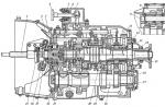
The design diagram of the STN type transformer of the system of Academician V.P. Nikitin and its external static characteristics are shown in Fig. 1. Magnetic leakage and inductive resistance of the windings (1 and 2) of the transformer are small, the external characteristic is hard. The falling characteristic is created due to the reactive winding 3, which creates an inductive resistance. The upper part of the magnetic circuit is also part of the inductor core.
The value of the welding current is regulated by moving the movable package 4 (by a screw mechanism using the handle 5). The open circuit voltage of these transformers is 60-70 V, and the rated operating voltage Unom = 30 V. Despite the combined magnetic circuit, the transformer and the inductor operate independently of each other. In electrical terms, transformers of the STN type do not differ from transformers with separate chokes of the STE type.
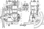
For automatic and semi-automatic welding, transformers of the TSD type are used. A general view of the design of the TSD-1000-3 transformer and its electrical circuit are shown in fig. 2 and 3.
Transformers type TSD have an increased open-circuit voltage (78-85 V), which is necessary for stable excitation and burning of the welding arc during automatic submerged arc welding. The falling external characteristic of the transformer is created by the reactive winding.
The TSD type transformer has a special electric drive for remote control of the welding current. To turn on the drive synchronous three-phase electric motor DP with a step-down worm gear, two magnetic starters PMB and PMM, controlled by buttons, are used. The movement of the moving part of the magnetic core package is limited by the VKB and VKM limit switches.
The transformers are equipped with filters to suppress radio interference. In addition to being used for automatic and semi-automatic submerged arc welding, TSD-1000-3 and TSD-2000-2 transformers are used as a power source for heat treatment of welded joints made of alloyed and low-alloyed steels.
|
|
| Rice. 1. (a) and its external characteristics (b): 1 - primary winding, 2 - secondary winding, 3 - inductor winding, 4 - movable magnetic circuit package, 5 - handle, 6 - magnetic circuit. |
|
|
| Rice. 2. : 1 - fan, 2 - transformer windings, 3 - magnetic circuit, 4 - reactive winding, 5 - movable package of magnetic drive, 6 - mechanism for moving the movable package, 7 - frame, 8 - clamping panels, 9 - running gear. |
|
|
|
Rice. 3. : Tr - step-down transformer, KUB, KUM - buttons for remote control of welding current - "More", "Less", PMB, PMM - magnetic starters, DP - motor of the wire of the mechanism for moving the magnetic core package, VKB, VKM - limit switches, DV - motor fan, Trs - welding transformer |


Transformers with developed magnetic dissipation
Transformers of the TC and TSK types are mobile step-down rod-type transformers with increased leakage inductance. They are designed for manual arc welding and surfacing, can be used for submerged arc welding with thin wires. In transformers of the TSK type, a capacitor is connected in parallel with the primary winding to increase the power factor.
Transformers such as TS, TSK do not have moving cores that are prone to vibration, so they operate almost silently. The welding current is regulated by changing the distance between the moving coil I and the fixed coil II (Fig. 1, c). When the moving coil is moved away from the fixed coil, the leakage magnetic fluxes and the inductive resistance of the windings increase. Each position of the moving coil has its own external characteristic. The farther apart the coils are, the greater the number of magnetic lines of force will close through the air spaces without capturing the second winding, and the steeper the external characteristic will be. The open-circuit voltage in transformers of this type with shifted coils is 1.5-2 V higher than the nominal value (60 - 65 V)
The design of the TC-500 transformer and external current-voltage characteristics are shown in the figures. Technical data of transformers TS and TSK are given in Table. 1 .
For automatic welding, welding transformers of the TDF-1001 and TDF-1601 types have been used, designed to power the arc during submerged arc welding with a single-phase alternating current with a frequency of 50 Hz. Transformers are designed for operation in enclosed spaces, with increased leakage inductance. They ensure the creation of the necessary steeply falling external characteristics and the smooth regulation of the welding current within the required limits, as well as its partial stabilization in case of voltage fluctuations in the network ranging from 5 to 10% of the nominal value. The technical data of the TDF type transformer are given in Table. 2.
Technical characteristics of transformers STSH-250 and TSP-2
| Options | TDF-1001 | TDF-1601 |
| Rated welding current, A | 1000 | 1600 |
| Limits of regulation of welding current, A: - at the stage of "small" currents - at the stage of "large" currents |
400-700 700-1200 |
600-1100 1100-1800 |
| Rated primary voltage, V | 220 or 380 | 380 |
| frequency Hz | 50 | 50 |
| Primary current, A: - for 220 V version - for 380 V version |
360 220 |
- 480 |
| Secondary open circuit voltage, V: - at minimum welding current - at maximum welding current |
68 71 |
95 105 |
| Conditional rated operating voltage, V | 44 | 60 |
| Secondary voltage depending on the values of welding current (Isv), V |
Un=20+0.04 Iv | Un=50+0.00625 Iv |
| Working hours ratio period to cycle duration (PV),% |
100 | 100 |
| Efficiency, % | 87 | 88 |
| Power consumption, kW | 82 | 182 |
| Weight, kg | 740 | 1000 |
The external characteristics of the transformer TDF-1001 and TDF-1601 are shown in fig. 2, a and b.
Transformers of the TDF-1001 and TDF-1601 types are stationary installations in a single-case design with forced ventilation. The installation consists of a transformer, a mains contactor, a fan and a control block diagram.
|
|
|
| Rice. 2. External characteristics of transformers: a - TDF-1001, b - TDF-1601. | |
 |
|
|
Rice. 3. Electrical diagram of the transformer STSH-500: 1 - magnetic circuit; 2 - primary winding coil; 3 - coil of the secondary winding; 4 - magnetic shunts Rice. 4. Electric circuit of the transformer TM-300-P |
|
 |
|
| Rice. 1. (a), its external current-voltage characteristics (b) and magnetic circuit (c): 1 - welding current control mechanism, 2 - low voltage clamps, 3 - moving coil, 4 - magnetic circuit, 5 - fixed coil, 6 - casing , 7 - adjusting screw, 8 - high voltage clamps, 9 - cover. | Rice. 5. (a) and its external characteristics (b): I, II, III, IV - switching circuits for various current values; 1, 2, 3, 4, 5, 6, 7 - terminal numbers |


Transformers with magnetic shunts such as STAN, OSTA and STSH (currently not available).
Transformer STSH rod type, single-phase, made in a single-case design and designed to power an electric welding arc with alternating current with a frequency of 50 Hz during manual arc welding, cutting and surfacing of metals. On fig. 3 shows the diagram of the STSH-500 transformer.
The magnetic core (transformer core) is made of electrical steel E42 with a thickness of 0.5 mm. Steel sheets are connected with insulated studs.
The coils of the primary winding of the transformer are made of insulated aluminum wire of rectangular cross section, and the secondary coils are made of a bare aluminum bus, between the turns of which asbestos gaskets are laid to isolate the turns from short circuits.
The current regulator consists of two movable magnetic shunts located in the magnetic circuit window. By turning the screw clockwise, the shunts move apart, and counterclockwise they move, the welding current is smoothly regulated. The smaller the distance between the shunts, the lower the welding current, and vice versa. Shunts are made from the same electrical steel as the magnetic core.
To reduce the interference that occurs during welding, a capacitive filter of two capacitors of the KBG-I type is used. The capacitors are mounted on the high voltage side.
The industry has created a number of new portable power sources for the welding arc with alternating current - small-sized transformers. Examples of such transformers are, for example, installation transformers TM-300-P, TSP-1 and TSP-2.
Mounting transformer TM-300-P is designed to power the welding arc during single-station arc welding during installation, construction and repair work. The transformer provides a steeply falling external characteristic (with a ratio of short-circuit current to the current of the rated operating mode of 1.2-1.3) and stepwise regulation of the welding current, which allows welding with electrodes with a diameter of 3.4 and 5 mm. It is single hull, light weight and easy to transport. The TM-300-P transformer has separate windings, which makes it possible to obtain a significant inductive resistance to create falling external characteristics. The core-type magnetic core is made of cold-rolled textured steel E310, E320, E330 with a thickness of 0.35-0.5 mm. The electrical circuit of the transformer is shown in fig. 4.
The primary winding consists of two coils of the same size, completely placed on one core of the magnetic circuit. The secondary winding also consists of two coils, of which one - the main one - is placed on the core of the magnetic circuit along with the primary winding, and the second - reactive - has three taps and is placed on the other core of the magnetic circuit.
The reactive secondary winding is significantly removed from the primary winding and has large leakage fluxes, which determine its increased inductive resistance. The value of the welding current is regulated by switching the number of turns of the reactive winding. Such current regulation makes it possible to increase the open-circuit voltage at low currents, providing conditions for stable burning of the welding arc.
The primary winding is made of copper wire with insulation, and the secondary winding is wound with a shank. The windings are impregnated with FG-9 silicon lacquer, which makes it possible to increase their heating temperature to 200°C. The magnetic circuit with the windings is placed on a trolley with two wheels. For welding under installation conditions with electrodes with a diameter of 3 and 4 mm, a lightweight transformer TSP-1 is used. The transformer is designed for short-term operation with a load factor of the post less than 0.5 and electrodes with a diameter of up to 4 mm. The electrical circuit and external characteristics of such a transformer are shown in fig. 5. Due to the large distance between the primary winding A and the secondary winding B, significant fluxes of magnetic leakage are formed.
The voltage drop due to the inductive resistance of the windings provides steeply falling external characteristics.
Regulation of welding current step, as well as at the welding transformer TM-300-P.
To reduce the weight, the design of the transformer is made of high quality materials - the magnetic circuit is made of cold-rolled steel, and the windings are made of aluminum wires with heat-resistant glass insulation.
Technical data of the TSP-1 transformer are given in table 1.
For welding in installation conditions, small-sized lightweight welding transformers STSH-250 with smooth regulation of welding current, developed by the E. O. Paton Electric Welding Institute, and TSP-2, developed by the All-Union Research Institute of Electric Welding Equipment, are also produced.
To carry out welding work at various heights under installation conditions, a special welding transformer TD-304 on a skid was created, equipped with remote control of the welding current directly from the workplace of the electric welder.
Multi-stage and special welding transformers
For multi-station welding any welding transformer of the STE type with a rigid external characteristic can be used, provided that a current regulator (choke) of the RST type is connected to each post, providing a falling external characteristic.
The number of posts connected to a multi-station welding transformer is determined by the formula
n=Itr / Ip ּ K,
where n is the number of posts; Itr - rated current of the welding transformer; Ip - welding current of the post; K - load factor equal to 0.6-0.8.
On fig. 1 shows the electrical circuit of multi-station welding from a single-phase transformer with a rigid characteristic and a current regulator of the RST type.
The use of multi-post welding transformers allows more complete use of the power of the equipment. For multi-post welding, three-phase transformers with parallel power supply of several welding posts are also used. As can be seen from fig. 2, such a transformer has a delta-connected primary winding 1 and a star-connected secondary winding 2. The phase voltage (voltage between the bullet wire and any of the phases) should be 65-70 V. The welding current is regulated and the falling characteristic is provided at each welding station using PCT chokes.
Multi-stage welding transformers are of limited use. A three-phase welding transformer can be used for manual arc welding with two electrodes (Fig. 3). In this case, greater welding productivity is ensured, energy is saved, the cosine "phi" is greater, the load is more evenly distributed between the phases. The current regulator of such a transformer Tr consists of two cores with adjustable air gaps. Two regulator windings 1 and 2 are located on the same core and are connected in series with the electrodes, winding 3 is on the second core and is connected to the structure to be welded. In three-phase welding, three arcs burn simultaneously according to the scheme under consideration: two between each of the electrodes 4, 5 and the workpiece 6 and one between electrodes 4 and 5. To stop the arc burning between electrodes 4 and 5, a magnetic contactor K is provided, the coil of which is connected in parallel to the winding 3 regulators and breaks the electrical circuit between the electrodes.
Parallel connection of single-phase welding transformers
Welding transformers are connected for parallel operation in order to increase the power of the power source. To do this, use two or more transformers of the same type with the same external characteristics and primary windings designed for the same voltage. The connection must be made to the same phases of the network of the corresponding clamps of the primary windings of the transformers of the same name, their secondary windings are also connected through the clamps of the same name.
The scheme of parallel connection of single-phase welding transformers with chokes of the STE type is shown in the figure. When two transformers are connected in parallel, the value of the welding current in the circuit increases, respectively, by 2 times compared with one transformer. Accordingly, with the connection of three transformers for parallel operation, the current increases by 3 times.
A necessary condition for the parallel operation of transformers is the uniform distribution of the welding current between them. The amount of welding current should be adjusted simultaneously by the same number of turns of the knobs of all regulators or by simultaneously pressing the buttons (as, for example, in transformers of the TSD type). The equality of loads between transformers is checked by ammeters.
Oscillators and impulse arc exciters
Oscillator- this is a device that converts low voltage industrial frequency current into high frequency current (150-500 thousand Hz) and high voltage (2000-6000 V), the imposition of which on the welding circuit facilitates excitation and stabilizes the arc during welding.
The main application of oscillators was found in argon-arc welding with alternating current with a non-consumable electrode of metals of small thickness and in welding with electrodes with low ionizing properties of the coating. The circuit diagram of the OSPZ-2M oscillator is shown in fig. 1.
The oscillator consists of an oscillatory circuit (capacitor C5, a movable winding of a high-frequency transformer and an arrester R) and two inductive choke coils Dr1 and Dr2, a step-up transformer PT, and a high-frequency high-frequency transformer are used as an induction coil.
The oscillatory circuit generates a high-frequency current and is inductively connected to the welding circuit through a high-frequency transformer, the secondary windings of which are connected: one to the grounded terminal of the output panel, the other through capacitor C6 and fuse Pr2 to the second terminal. To protect the welder from electric shock, capacitor C6 is included in the circuit, the resistance of which prevents the passage of high voltage and low frequency current into the welding circuit. In the event of a breakdown of the capacitor C6, a Pr2 fuse is included in the circuit. The OSPZ-2M oscillator is designed to be connected directly to a two-phase or single-phase network with a voltage of 220 V.
 |
 |
| Rice. 1. : ST - welding transformer, Pr1, Pr2 - fuses, Dr1, Dr2 - chokes, C1 - C6 - capacitors, PT - step-up transformer, VChT - high-frequency transformer, R - arrester | Rice. 2. : Tr1 - welding transformer, Dr - choke, Tr2 - step-up transformer of the oscillator, R - arrester, C1 - circuit capacitor, C2 - protective circuit capacitor, L1 - self-induction coil, L2 - communication coil |
During normal operation, the oscillator crackles evenly, and due to the high voltage, the gap of the spark gap breaks down. The spark gap should be 1.5-2 mm, which is regulated by compressing the electrodes with an adjusting screw. The voltage on the elements of the oscillator circuit reaches several thousand volts, so the regulation must be performed with the oscillator turned off.
The oscillator must be registered with the local telecommunications inspectorate; during operation, monitor its correct connection to the power and welding circuits, as well as the good condition of the contacts; work with the cover on; remove the casing only during inspection or repair and with the mains disconnected; monitor the good condition of the working surfaces of the arrester, and if soot appears, clean them with sandpaper. Oscillators with a primary voltage of 65 V are not recommended to be connected to the secondary terminals of welding transformers such as TS, STN, TSD, STAN, since in this case the voltage in the circuit decreases during welding. To power the oscillator, you need to use a power transformer with a secondary voltage of 65-70 V.
The connection diagram of the M-3 and OS-1 oscillators to the STE type welding transformer is shown in Fig. 2. The technical characteristics of the oscillators are given in the table.
Specifications of the oscillators
| Type | Primary voltage, V |
secondary voltage idling, V |
Consumed Power, W |
Dimensional dimensions, mm |
Weight, kg |
| M-3 OS-1 OSPC TU-2 TU-7 TU-177 OSPZ-2M |
40 - 65 65 200 65; 220 65; 220 65; 220 220 |
2500 2500 2300 3700 1500 2500 6000 |
150 130 400 225 1000 400 44 |
350x240x290 315x215x260 390x270x310 390 x 270 x 350 390 x 270 x 350 390 x 270 x 350 250 x 170 x 110 |
15 15 35 20 25 20 6,5 |
Pulsed arc exciters
These are devices that serve to supply synchronized pulses of increased voltage to the welding arc of alternating current at the moment of polarity change. Thanks to this, the re-ignition of the arc is greatly facilitated, which makes it possible to reduce the open-circuit voltage of the transformer to 40-50 V.
Pulse exciters are used only for gas-shielded arc welding with a non-consumable electrode. Exciters from the high side are connected in parallel to the power supply of the transformer (380 V), and at the output - in parallel to the arc.
Powerful serial exciters are used for submerged arc welding.
Pulse arc exciters are more stable in operation than oscillators, they do not create radio interference, but due to insufficient voltage (200-300 V) they do not provide arc ignition without electrode contact with the workpiece. There are also cases of combined use of an oscillator for the initial ignition of the arc and a pulsed exciter to maintain its subsequent stable burning.
Welding arc stabilizer
To increase the productivity of manual arc welding and economical use of electricity, a welding arc stabilizer SD-2 was created. The stabilizer maintains a stable burning of the welding arc when welding with alternating current with a consumable electrode by applying to the arc at the beginning of each period of a voltage pulse.
The stabilizer expands the technological capabilities of the welding transformer and allows you to perform AC welding with UONI electrodes, manual arc welding with a non-consumable electrode of products made of alloyed steels and aluminum alloys.
The scheme of external electrical connections of the stabilizer is shown in fig. 3, a, the oscillogram of the stabilizing pulse - in fig. 3b.
Welding with the use of a stabilizer makes it possible to use electricity more economically, expand the technological possibilities of using a welding transformer, reduce operating costs, and eliminate magnetic blast.
Welding device "Discharge-250". This device was developed on the basis of the TSM-250 welding transformer and the welding arc stabilizer, which produces pulses with a frequency of 100 Hz.
The functional diagram of the welding device and the oscillogram of the open-circuit voltage at the output of the device are shown in fig. 4, a, b.
 |
 |
|
Rice. 3. : a - diagram: 1 - stabilizer, 2 - cooking transformer, 3 - electrode, 4 - product; b - oscillogram: 1 - stabilizing pulse, 2 - voltage on the secondary winding of the transformer |
Rice. 4. a - device diagram; b - oscillogram of open-circuit voltage at the output of the device |
The Discharge-250 device is designed for manual arc welding with alternating current with consumable electrodes of any type, including those intended for welding with direct current. The device can be used when welding with non-consumable electrodes, for example, when welding aluminum.
Stable arc burning is ensured by applying to the arc at the beginning of each half period of the alternating voltage of the welding transformer a voltage pulse of direct polarity, i.e., coinciding with the polarity of the specified voltage.
The initial data for such a calculation are: P nom - rated short-term power of the transformer, PV nom - rated on-time, U 1 - voltage in the network supplying the machine, E 2 - e. d.s. secondary winding, as well as the limits and number of steps of regulation. Rnom and E 2 are usually set for the case of turning on the transformer at the penultimate stage, which, when turned on at the last, highest stage (E 2 has the maximum value), provides some power reserve.
The calculation of a welding transformer begins with determining the dimensions of the core. The core cross section (in cm 2) is determined by the formula
Where E 2- estimated e. d.s. secondary winding of the transformer in V
f- AC frequency (typically 50 Hz)
w2- the number of turns of the secondary winding (one, rarely two);
IN- maximum allowable induction in gauss (gs)
k- coefficient taking into account the presence between thin steel sheets from which the core is assembled, insulation and air gaps.
Permissible induction B depends on the steel grade. When using alloyed transformer steel in resistance welding transformers, the maximum induction usually lies in the range of 14000 - 16000 gauss.
With good contraction of the core from sheets 0.5 mm thick insulated with varnish, k - 1.08; with paper insulation, k can rise to 1.12.
In an armored transformer with a branched magnetic circuit, the calculated cross section obtained by the formula refers to the central rod that passes the full magnetic flux. The cross section of the remaining sections of the magnetic circuit, passing half the flow, is reduced by 2 times.
The cross section of each transformer rod is usually a rectangle with an aspect ratio of 1:1 to 1:3.
The number of turns of the primary winding depends on the limits of regulation of the secondary voltage of the transformer. This regulation is in most cases achieved by changing the transformation ratio by turning on more or less turns of the primary winding. For example, with a primary voltage of 220 V and a maximum value of E 2 \u003d 5 V, the transformation ratio is 44 and with one turn of the secondary winding, the primary winding should have 44 turns; if it is necessary to lower E 2 (in the process of regulating the power of the transformer) to 4, the transformation ratio rises to 55, which requires 55 turns of the primary winding. Usually, the control limits of contact machines (the ratio E 2 max / E 2 min) vary from 1.5 to 2 (in some cases, these limits are even wider). The wider the regulation limits of the transformer (the smaller E 2 min at a constant value of E 2 max), the more turns its primary winding should have and the correspondingly more copper consumption for the manufacture of the transformer. In this regard, wider control limits are used in machines of a universal type (this expands the possibility of their use in production) and narrower ones - in specialized machines designed to perform a specific welding operation.
Knowing the value of E 2 for the nominal stage and the control limits, it is easy to calculate the total number of turns of the primary winding using the formula
With two turns of the secondary winding, the resulting value w l doubles.
The number of power control steps of a resistance welding transformer usually lies in the range of 6-8 (sometimes it increases to 16 or even 64). The number of turns included at each stage of regulation is selected in such a way that the ratio between e. d.s. for any two adjacent steps was approximately the same.
The cross section of the primary winding wire is calculated from the continuous current at the rated stage I l ave. The short-term rated current is preliminarily determined by the formula
The continuous current is calculated from the nominal value of PV%, using the formula or graph in Fig. 128. The wire cross section is calculated by the formula
where j lnp is the allowable continuous current density in the primary winding. For copper wires of the primary winding with natural (air) cooling j lnp \u003d 1.4 - 1.8 a / mm 2. With a snug fit of the primary winding to the elements of the secondary coil, which have intensive water cooling, the current density in the primary winding can be significantly increased (up to 2.5 - 3.5 A / mm 2) due to their better cooling. As mentioned above, the cross section of the turns of the primary winding, which are switched on only at low stages of regulation (at a relatively low current), can be reduced in comparison with the cross section of the turns that pass the maximum current, when switched on at the last stage. The required cross section of the secondary coil is determined by the continuous current I 2pr in the secondary circuit of the machine. Approximately I 2pr \u003d n * I 1pr,
where n is the transformation ratio at the nominal turn-on stage of the transformer. The cross section of the secondary coil is
Depending on the design and method of cooling in the copper secondary coil, the following current densities can be allowed: in an uncooled flexible coil made of copper foil - 2.2 A / mm 2; in a coil with water cooling - 3.5 a / mm 2; in an uncooled rigid coil - 1.4-1.8 a / mm 2. With an increase in current density, the weight of copper decreases, but losses in it increase and the efficiency of the transformer decreases.
The number of turns of the primary and secondary windings of the transformer and their cross section (taking into account the location of the insulation) determine the size and shape of the window in the core of the transformer, in which the winding elements should be placed. This window is usually designed with an aspect ratio of 1:1.5 to 1:3. The elongated shape of the window makes it possible to place the windings without resorting to a high coil height, which leads to an increase in copper consumption due to a noticeable elongation of the outer turns of the winding. The dimensions of the window and the previously found sections of the core rods completely determine the shape of the latter.
The next step in the calculation of the transformer is to determine its no-load current. To do this, the weight of the core is preliminarily calculated and the active energy losses in it R f are determined. Further, the active component of the no-load current is calculated by the formula
And its reactive component (magnetizing current) - according to the formula ![]() . The total no-load current is defined as the length of the hypotenuse in a right triangle
. The total no-load current is defined as the length of the hypotenuse in a right triangle
The work of the welding transformer is based on the phenomenon of electromagnetic induction. The idle mode of the transformer is set with the secondary winding open at the moment the primary winding is connected to the AC mains with voltage U1.
Transformer operation
In this case, current I1 flows through the primary winding, which creates an alternating magnetic flux Ф1. This flux induces an alternating voltage U2 in the secondary winding. Since the secondary circuit is open, no current flows in it I2 = 0 and there is no energy consumption in the secondary circuit. Therefore, the secondary voltage at no-load is maximum and this value is called the no-load voltage U2 \u003d Uxx.
The ratio of the voltages of the primary and secondary windings at idle is called the transformation ratio K. It is also equal to the ratio of the number of turns of the primary winding w1 and the secondary winding w2:

In welding transformers, the mains voltage of 220 V or 380 V is converted into a lower open-circuit voltage U2 = Uхх = 60...80 V.
The load mode is set due to the closure of the secondary winding circuit at the moment of ignition of the arc. In this case, under the action of voltage U2, a current I2 = Ist appears in the secondary winding and the arc. This current in the core creates an alternating magnetic flux, which tends to reduce the amount of flux created by the primary winding F1. Counteracting this, the current strength in the primary winding increases. The increase in energy consumption in the primary winding should be equal to the increase in the energy output of the arc by the secondary winding in accordance with the law of conservation of energy.
The voltage in the secondary winding of the transformer under load is:

where Ud is the voltage drop across the arc; XL is the inductive resistance of the welding circuit.
The ohmic resistance of the welding circuit R, including the electrode extension, is much less than the inductive resistance XL. For this reason, when calculating U2, the value of R is neglected.
Part of the magnetic flux Fr along the way from the primary winding to the secondary is dissipated in space. The leakage magnetic flux is greater, the greater the distance between the windings.
As a result, the secondary winding permeates the magnetic flux Ф2. The falling external current-voltage characteristic of the welding transformer is obtained due to a change in the magnitude of the dissipation of the magnetic flux Fr.
In this case, the arc voltage Ud decreases Ud \u003d U2 - Iw XL with an increase in the strength of the welding current Iw and inductive resistance XL.
As shown in the figure below, the transformer can be adjusted:
by changing the inductive reactance of the welding transformer XL,
by changing the open circuit voltage Uxx.

Regulation of the strength of the welding current Iw, the strength of the short circuit current Ikz and the no-load voltage Uxx of the transformer
The first method is more common and allows you to smoothly adjust the welding current. The second method is used as an additional one. As a rule, the transformer has one or two fixed values \u200b\u200bof Uxx and U "xx. U" xx is obtained by installing additional sections in the primary or secondary windings. With an open-circuit voltage value U "xx, as with Uxx, it is possible to smoothly adjust the inductive resistance XL, and therefore the welding current Iw and the short-circuit current Ikz.
Smooth dual-range current regulation allows to reduce the weight and dimensions of the transformer. To obtain a high current range, both primary and secondary coils are connected in pairs in parallel, as shown in the figure below. To obtain a range of low currents, the coils of the primary and secondary windings are connected in series.
![]()
Structural diagram of a welding transformer with moving coils of the secondary winding
Regulation of the welding current Iw (as well as Ikz) at a constant open-circuit voltage of the transformer Uxx is possible only by changing the inductive resistance.
In the existing designs of transformers, the regulation of the inductive resistance of the secondary circuit can be performed:
changing the distance between the primary and secondary windings;
by changing the gap of the magnetic circuit of the inductor, made separately from the transformer.
The first option is interesting for its simple and reliable design. However, if it is necessary to weld at a distance of 10 ... 40 meters from the transformer, then a separate regulator will always be at hand for the welder. Such a regulator weighs much less than a transformer, so it is easier to move.
In the event of a short circuit, the electrode touches the product Ud \u003d 0. The voltage in the secondary winding U2 \u003d Ikz XL. From here
Voltage over 36 volts is considered dangerous in the mains. The secondary open-circuit voltage of welding transformers reaches 80 volts, and when carrying out electric welding work, the welder can get an electric injury and in damp rooms and with a fatal outcome.
The secondary open-circuit voltage during the welding process decreases according to the steeply falling load characteristic.
The use of primary protective equipment in the production of welding work, in the form of rubber gloves and boots, creates additional inconvenience and does not always protect against electric shock.
The use of welding machines with a low voltage of the secondary circuit will lead to unstable ignition of the welding arc, the duration of the ignition time is not less than 20 ms - not less than the contact time of the welding electrode with the workpiece. Almost all factory welding transformers have an open circuit voltage of 80 volts and an operating voltage of 36-46 volts AC at maximum welding arc current.
The use of stationary devices to reduce the open circuit voltage of welding machines in a portable version is impossible for a number of reasons: large dimensions and weight, mandatory secondary grounding, malfunctions from fuzzy switching when using relay switching.
Device Purposes:
It is possible to reduce the secondary voltage of the welding machine by simple methods:
1. Install a resistor in the primary circuit - a rheostat with smooth resistance adjustment. The disadvantage of such a device is the large dimensions and the loss of electricity for heating the resistance, the inability to automatically maintain the voltage of the secondary circuit in the given aisles.
2. You can get rid of heat losses by the second method - supplying the primary winding through an isolation capacitor, the disadvantage of such an inclusion is that under certain conditions a voltage resonance is created and their almost double growth on the capacitor and transformer windings.
This can lead to failure of these elements and even fire.
3. The third way to reduce the open circuit voltage is simple to implement, but requires additional costs for the implementation of the circuit for limiting the idling of the welding machine, allows you to maintain the secondary voltage at a safe level for an arbitrarily long time, automatically, almost instantly, ignites the arc in any condition of the surface of the metal being welded .
Device specifications:
Mains voltage -220/380 V.
The power of the welding machine is not limited.
Welding current - not limited.
The open circuit voltage of the welding circuit is 16-36 volts AC.
The ignition voltage of the welding arc is -80 -120 volts.
Arc ignition time 8-16 ms.
Mains frequency 50 Hz.
Energy savings at duty cycle 30% to 62%.
Current regulation 36%.
Purpose of using the device:
1) protection of personnel in the production of welding work in hazardous industrial and domestic conditions
2) reducing the voltage of the welding circuit to acceptable limits
3) limiting the loading of the electrical network by no-load currents
4) lowering the temperature of the welding transformer during operation
5) improving the quality of welding due to the possible regulation of the welding current and stable ignition of the arc
6) saving electricity consumed by the unit for idling.
The principle of operation of the device consists in the preliminary limitation of the open circuit voltage of the welding circuit, automatic, stable, ignition of the welding arc, by briefly supplying increased voltage to the welding circuit and maintaining the welding current in the established aisles.
Device diagram limiting the idling of the welding machine consists of a budget power welding transformer T 3 (Fig. 1) with protection circuits FU1 and switching SA1 of the primary circuit and secondary circuit elements - a diode bridge VD 7, a choke L 1 and a filter capacitor C7.
A powerful triac VS1 with anti-interference circuits C6, R15 is included in the break in the primary circuit of the welding transformer.
In the secondary circuit of the welding transformer T3, a current transformer T2 is installed to remove the feedback signal necessary to start the circuit and adjust the welding current.
For galvanic isolation of the control unit circuit from the dangerous effects of the mains, the electronic circuit is powered through a power transformer T1, and the triac VS1 is controlled through a dinistor optocoupler DA2 included in the collector circuit of the amplifier on the transistor VT2. The HL1 LED indicates the operating status of the device.
A programmable analog timer on the DA1 chip allows you to set the necessary operating modes of the device in time.
The input amplifier of the feedback signal on the transistor VT1 allows you to pre-amplify a weak signal to a level sufficient to switch the timer to the operating mode, with the development of functions - limiting the open circuit voltage, pulse ignition of the welding arc and setting the operating current depending on the cross section of the welding electrode.
When the welding current passes through the winding (1) of the current transformer T2, a small voltage arises, which, after rectification by the diode bridge VD4, is smoothed out by the capacitor C4 and stabilized at the level of three volts by the stabilizer VD3. From the setting resistor R7 through the reverse diode VD2, the feedback voltage is fed to the input of the pre-amplifier on the transistor VT1. The gain depends on the properties of the transistor and the values of the resistors R1, R2, R3. The initial collector voltage of 2/3 Up prohibits the start of the DA1 timer, and in the presence of a feedback input signal, the transistor VT1 instantly switches and the collector voltage drops to 1/3 Up, which creates the conditions for starting the timer. Capacitor C2 improves switching conditions and delays switching off by a fraction of a second when the welding electrode breaks, protecting against arc loss.
A low level at the input 2DA1 of the lower timer comparator of the standby multivibrator allows its operation and a high level appears at the output (3).
The waiting multivibrator on the timer begins to generate a rectangular voltage pulse at the output with a duration of T1 \u003d 1.1 (R4 + R5) C1, at the end of this process and when the voltage on the capacitor reaches 2 / 3U, the upper comparator is triggered at the input (6) DA1, the output of the microcircuit switches to the zero state, the internal transistor of the timer will open and discharge the capacitor C1 with time T2 = C1R6. If there is a feedback signal, the process of generating rectangular pulses will continue.
The power supply of the microcircuit and the preamplifier is made from a parametric stabilizer on the zener diode VD1 and a limiting resistor R8.
Pulses of positive polarity through resistor R9 from output 3 DA1 of the timer are fed to the base VT2 of the transistor amplifier, and resistors R7 set the open circuit voltage of the secondary winding of the welding transformer.
Transistor VT2 with a frequency determined by the parameters of the external elements of the timer DA1 through the optocoupler DA2 opens the triac VS1 in both polarities of the AC network.
The radio components in the circuit are factory-installed: resistors MLT -0.125 or C-29 -0.12, resistor R16 with a power of at least two watts. Capacitors type KM and K50. Reverse conduction transistors with a gain of at least V -100 of the KT315 and KT815B types, respectively, with a circuit. Instead of the DA1 timer, you can install an analogue of the 555 or 7555 series.
The type of triac used depends on the welding transformer. Current transformer T2 type TK 20 -100 / 5.
Power transformer T1 - CCI -112 for a voltage of 8-10 volts and a current of at least 100 mA, a power of 8-15 watts.
The board of the device for limiting idling of the welding transformer is installed in a housing of the appropriate size, the current transformer T2 is separately placed, it is possible to install the device outside the housing of the welding machine.
Device setup start by monitoring the voltage across the resistor R8. The upper output of the resistor R7 must first be disconnected from the circuit. Resistor R5 with temporarily closed outputs 2.6 DA1 set the secondary voltage of the welding transformer is not lower than 16 volts and not higher than 36 volts, depending on the operating conditions. Next, having closed the welding circuit with an electrode with a diameter of 3 mm, set the switching point of the DA1 timer with the resistor R7 to increase the brightness of the control LED HL1 and the appearance of full voltage on the secondary winding of the transformer T3. Resistor R4 regulates the welding current within small limits. The scheme of the device is made on a board with dimensions of 140 * 35 mm from one-sided foil fiberglass.
Literature:
1.S.Zamkova. Welding transformer voltage limiter. "Radio" No. 8, 1984, pp. 55-56.
List of radio elements
| Designation | Type | Denomination | Quantity | Note | Shop | My notepad |
|---|---|---|---|---|---|---|
| DA1 | Programmable timer and oscillator | NE555 | 1 | KR1006VI11 | To notepad | |
| VT1 | bipolar transistor | KT3102B | 1 | To notepad | ||
| VT2 | bipolar transistor | KT972A | 1 | To notepad | ||
| VD1 | zener diode | KS210B | 1 | To notepad | ||
| VD2 | zener diode | KS512B | 1 | To notepad | ||
| VD3 | zener diode | KS133A | 1 | To notepad | ||
| VD4-VD6 | Diode bridge | KTS407A | 3 | To notepad | ||
| VD7 | Diode | D160 | 4 | To notepad | ||
| VS1 | Thyristor & Triac | TS132-40-12 | 1 | To notepad | ||
| DA2 | optocoupler | AOU103V | 1 | To notepad | ||
| C1, C3 | Capacitor | 0.01uF | 2 | To notepad | ||
| C2 | 1 uF | 1 | To notepad | |||
| C4 | electrolytic capacitor | 10 uF | 1 | To notepad | ||
| C5 | electrolytic capacitor | 470uF 50V | 1 | To notepad | ||
| C6 | Capacitor | 1uF 600V | 1 | To notepad | ||
| C7 | electrolytic capacitor | 10000uF 100V | 1 | To notepad | ||
| C7 | Capacitor | 0.1uF 600V | 1 | To notepad | ||
| R1 | Resistor | 16 kOhm | 1 | To notepad | ||
| R2 | Resistor | 1 MΩ | 1 | To notepad | ||
| R3 | Resistor | 1.2 kOhm | 1 | To notepad | ||
| R4 | Resistor | 3.6 kOhm | 1 | To notepad | ||
| R5 | Variable resistor | 220 kOhm | 1 | To notepad | ||
| R6 | Resistor | 120 ohm | 1 | To notepad | ||
| R7 | Trimmer resistor | 3.3 kOhm | 1 | To notepad | ||
| R8 | Resistor | 910 ohm | 1 | To notepad | ||
| R9 | Resistor | 560 ohm | 1 | To notepad | ||
| R10 | Resistor | 470 kOhm | 1 | To notepad | ||
| R11 | Trimmer resistor | 510 kOhm | 1 |
Welding transformers according to the phase of the electric current are divided into single-phase and three-phase, and according to the number of posts - into single-station and multi-station. Single station transformer serves to supply welding current to one workplace and has a corresponding external characteristic.
Multi-stage transformer serves to simultaneously power several welding arcs (welding stations) and has a rigid characteristic. To create a stable burning of the welding arc and ensure a falling external characteristic, a choke is included in the arc welding circuit. For arc welding, welding transformers are divided into two main groups according to their design features:
transformers with normal magnetic scattering, structurally made in the form of two separate devices (transformer and choke) or in a single common housing;
transformers with developed magnetic leakage, structurally differing in the method of regulation (with moving coils, with magnetic shunts, with step regulation).
In the USSR, transformers of both groups have found application, and in recent years, mainly transformers in a single-case design with developed magnetic scattering and with magnetic shunts.
Transformers with normal magnetic scattering.
Transformers with separate choke. The rigid external characteristic of such a transformer is obtained due to insignificant magnetic scattering and low inductive resistance of the transformer windings. Falling external characteristics are created by a choke having a large inductive resistance.
Technical data of STE-24U and STE-34U transformers with chokes are given in Table. 23.
Table 23
Specifications of welding transformers

Continuation of the table. 23

STN type transformers with built-in choke. According to this design scheme, transformers STN-500 and STN-500-1 for manual arc welding and remote-controlled transformers TSD-500, TSD-2000-2, TSD-1000-3 and TSD-1000-4 for automatic and semi-automatic welding under flux. The technical data of these transformers are given in Table. 23.
The design diagram of the STN type transformer of the system of Academician V.P. Nikitin and its external static characteristics are shown in Fig. 58. Magnetic leakage and inductive resistance of windings ( 1
And 2
) of the transformer are small, the external characteristic is rigid. The falling characteristic is created by a reactive winding 3
, which creates an inductive reactance. The upper part of the magnetic circuit is also part of the inductor core.

The value of the welding current is regulated by moving the movable package 4
(screw mechanism with handle 5
). The open circuit voltage of these transformers is 60 - 70 V, and the rated operating voltage U nom = 30 V. Despite the combined magnetic circuit, the transformer and inductor operate independently of each other. In electrical terms, transformers of the STN type do not differ from transformers with separate chokes of the ste type.
For automatic and semi-automatic welding, transformers of the TSD type are used. A general view of the design of the TSD-1000-3 transformer and its electrical circuit are shown in fig. 59 and 60.


Transformers of the TSD type have an increased open circuit voltage (78 - 85 V), necessary for stable excitation and burning of the welding arc in automatic submerged arc welding.
The falling external characteristic of the transformer is created by the reactive winding 4
. The TSD type transformer has a special electric drive for remote control of the welding current. To turn on the drive synchronous three-phase electric motor DP with a step-down worm gear, two magnetic starters PMB and PMM, controlled by buttons, are used. The movement of the moving part of the magnetic core package is limited by the VKB and VKM limit switches.
The transformers are equipped with filters to suppress radio interference. In addition to being used for automatic and semi-automatic submerged arc welding, TSD-1000-3 and TSD-2000-2 transformers are used as a power source for heat treatment of welded joints made of alloyed and low-alloyed steels.
Transformers with developed magnetic dissipation. Transformers type TS and TSK are mobile step-down rod-type transformers with increased leakage inductance. They are designed for manual arc welding and surfacing, can be used for submerged arc welding with thin wires. In transformers of the TSK type, a capacitor is connected in parallel with the primary winding to increase the power factor.
Transformers such as TS, TSK do not have moving cores that are prone to vibration, so they operate almost silently. Welding current is regulated by changing the distance between the movable I and motionless II coils (Fig. 61, c). When the moving coil is moved away from the fixed coil, the leakage magnetic fluxes and the inductive resistance of the windings increase. Each position of the moving coil has its own external characteristic. The farther apart the coils are, the greater the number of magnetic lines of force will close through the air spaces without capturing the second winding, and the steeper the external characteristic will be. Open circuit voltage in transformers of this type with coils shifted by 1.5 - 2 V more than the nominal value (60 - 65 V).

The design of the TC-500 transformer and external current-voltage characteristics are shown in fig. 61, a, b. Technical data of transformers TS and TSK are given in Table. 23.
Transformers with magnetic shunts such as STAN, OSTA and STSH.
Welding transformers of the STSH-500 (A-760) type developed by the Institute of Electric Welding named after E. O. Paton have high performance and long service life compared to transformers of the TS, TSK, TD types.
The STSH rod-type transformer, single-phase, is made in a single-case design and is designed to power an electric welding arc with alternating current with a frequency of 50 Hz in manual arc welding, cutting and surfacing of metals. On fig. 62 shows a diagram of the transformer STSH-500.

The magnetic circuit (transformer core) is made of electrical steel E42 with a thickness of 0.5 mm. Steel sheets are connected with insulated studs.
The coils of the primary winding of the transformer are made of insulated aluminum wire of rectangular cross section, and the secondary coils are made of a bare aluminum bus, between the turns of which asbestos gaskets are laid to isolate the turns from short circuits.
The current regulator consists of two movable magnetic shunts located in the magnetic circuit window. By turning the screw clockwise, the shunts move apart, and counterclockwise they move, the welding current is smoothly regulated. The smaller the distance between the shunts, the lower the welding current, and vice versa. Shunts are made from the same electrical steel as the mainline.
To reduce interference to radio receivers that occur during welding, a capacitive filter of two capacitors of the KBG-I type is used. The capacitors are mounted on the high voltage side.
At present, a number of new portable AC welding arc power sources have been created - small transformers. Examples of such transformers are, for example, installation transformers TM-300-P, TSP 1 and TSP-2.
Mounting transformer TM-300-P is designed to power the welding arc during single-station arc welding during installation, construction and repair work. The transformer provides a steeply falling external characteristic (with a ratio of short circuit current to the current of the rated operating mode 1.2 - 1.3) and stepwise regulation of the welding current, which allows welding with electrodes with a diameter of 3, 4 and 5 mm. It is single body, light weight and easy to transport. The TM-300-P transformer has separate windings, which makes it possible to obtain a significant inductive resistance to create falling external characteristics. The core-type magnetic core is assembled from cold-rolled textured steel E310, E320, E330 with a thickness of 0.35 - 0.5 mm. The electrical circuit of the transformer is shown in fig. 63.

The primary winding consists of two coils of the same size, completely placed on one core of the magnetic circuit. The secondary winding also consists of two coils, of which one - the main one - is placed on the core of the magnetic circuit along with the primary winding, and the second - reactive - has three taps and is placed on the other core of the magnetic circuit.
The reactive secondary winding is significantly removed from the primary winding and has large leakage fluxes, which determine its increased inductive resistance. The value of the welding current is regulated by switching the number of turns of the reactive winding. Such current regulation makes it possible to increase the open-circuit voltage at low currents, providing conditions for stable burning of the welding arc.
The primary winding is made of copper wire with insulation, and the secondary winding is wound with a shank. The windings are impregnated with FG-9 silicon lacquer, which makes it possible to increase their heating temperature to 200°C. The magnetic circuit with the windings is placed on a trolley with two wheels. For welding under installation conditions with electrodes with a diameter of 3 and 4 mm use a lightweight transformer TSP-1. The transformer is designed for short-term operation with a load factor of the post less than 0.5 and electrodes with a diameter of up to 4 mm. The electrical circuit and external characteristics of such a transformer are shown in fig. 64. Due to the large distance between the primary winding A and secondary winding B significant fluxes of magnetic scattering are formed. The voltage drop due to the inductive resistance of the windings provides steeply falling external characteristics.

Regulation of welding current step, as well as at the welding transformer TM-300-P.
To reduce weight, the construction of the transformer is made of high quality materials - the magnetic circuit is made of cold-rolled steel, and the windings are made of aluminum wires with heat-resistant glass insulation.
The technical data of the TSP-1 transformer are given in Table. 23.
For welding in installation conditions, small-sized lightweight welding transformers STSH-250 with smooth regulation of welding current, developed by the E. O. Paton Electric Welding Institute, and TSP-2, developed by the All-Union Research Institute of Electric Welding Equipment, are also produced. The main technical data of these transformers are given in Table. 24.
Table 24
Technical characteristics of transformers STSH-250 and TSP-2
To carry out welding work at various heights under installation conditions, a special welding transformer TD-304 on a skid was created, equipped with remote control of the welding current directly from the workplace of the electric welder. The main technical data of such a transformer in comparison with the TS-300 transformer are given in Table. 25.
Table 25
Technical characteristics of transformers TD-304 and TS-300