The site is in test mode. We apologize for errors and inaccuracies.
We ask you to write to us about inaccuracies and problems through the feedback form.
Battery capacity meter on a microcontroller.
The device developed by the author is designed to automatically measure the capacity of most types of batteries - from small-sized to car batteries. The principle of measurement is based on discharging the battery with a stable current with automatic calculation of the discharge time and further multiplication of these values, the result is obtained in the usual dimension - ampere-hours. The basis of the device is the microcontroller (MK) Atmega8, which works according to the program, the codes of which are given in the article. In addition to the MK, the meter contains three microcircuits (K155ID3, KR142EN5V, LM358N) and an IRL2505 transistor. To indicate the results, two LED digital indicators are used: a three-digit TOT3361 (it shows the value of the discharge current in the X.XX format) and a nine-digit E90361-L-F (shows the value of the capacity in ampere-hours in the XX.XXX format and the voltage to which the battery can be discharged, ranging from 1 to 25.5 V). The current voltage of the battery is monitored. The codes of the MK program and the drawing of the printed circuit board are given. The MK program will also be hosted on our FTP server at< ftp:// ftp . radio . ru / pub /2009/03/ izm . zip >.
This capacitance meter can measure the capacitance of capacitors with a resolution of 1 pF at the lower end of the range. The maximum measurable capacitance is 10,000 uF. The actual accuracy is not known, but the linear error lies within a maximum of 0.5%, and is usually less than 0.1% (obtained by measuring several capacitors connected in parallel). The greatest difficulties arise when measuring high-capacity electrolytic capacitors.
The capacitance meter works in the mode of automatic selection of measurement limits, or in the lower or upper range of capacities forcibly. The device has two different measurement limits, realizing two measurements for the same capacitor. This makes it possible to check the veracity of the measurement and find out whether the measured part is really a capacitor. With this method, electrolytes exhibit their characteristic non-linearity, giving different values at different measurement limits.
The capacitance meter has a menu system, which also allows you to calibrate the zero value and the capacitance of 1 uF. Calibration is stored in EEPROM.
One of the smallest chips, Atmega8, was chosen for the project. The circuit is powered by a 9V battery through a 7805 linear regulator. 
The device can operate in three modes: measurement in the lower range, in the upper range, and in discharge mode. These modes are determined by the state of the outputs PD5 and PD6 of the controller. During discharging, PD6 has a log. 0 and the capacitor is discharged through the resistor R7 (220 ohms). In the upper measurement range, PD5 has a log. 1, charging the capacitor through R8 (1.8K) and PD6 is in the Z-state to allow the analog comparator to compare the voltage. In the lower measurement range, PD5 is also in the Z-state, and the capacitor is charged only through R6 (1.8MΩ).
Any 16x2 character display on the HD44780 controller can be used as an indicator. The display connector pinout is shown in this figure:

The device is assembled on a breadboard and housed in a simple rectangular plastic case. Holes for the indicator, button and LED are cut out in the case cover, which are fixed with hot glue:

Capacitance meter program
The device can use atmega8 and atmega48/88/168 controllers of the family. When replacing the controller in the program, you need to change the line responsible for the configuration of the timer of a particular controller.
A modular version of a visual and accurate battery ampere-hour meter, assembled at minimal cost from computer garbage.
This is my response to the article.
A little prelude...
Under my patronage is a fleet of 70 computers, different years of release and condition. Naturally, the vast majority have uninterruptible power supplies (in the text - UPS). The organization is budgetary, of course they don’t give money, like - do what you want, but everything should work. After short tests with a load in the form of a 150-watt light bulb, I found that 70% of the UPSs do not hold the load for more than 1 minute, the APC UPSs sin with the switching relay contacts (it goes to the battery, buzzes, squeaks, and the output is completely zero). Of course, no one let me check all the UPSs at once. The way out turned out to be simple: once every half a year - a year I took the computers for cleaning, lubrication, and at the same time the UPS for a test and inspection of offal.
Of course, UPSs of different brands and capacities (there is an old man with 600 watts produced in 1992, the native battery died this fall, before that I did resuscitation 4 years ago). If someone is not in the know, batteries of different types, cases, voltages and capacities are used in household-office UPSs. The typical representative is GP1272F2 (12 Volt, 7 Ah). But they also come across 6V - 4.5 A / h.
Batteries often cost more than half the price of a new UPS. Moreover, in the desk (in which I work part-time), dead batteries also accumulate. The question arose, what is the real capacity before and after picking up from the trash can, how many minutes of work can be expected from the UPS. And then an article caught my eye I. Nechaeva In the magazine "Radio" 2/2009 about such a meter.
Of course, I didn’t like some moments, I’m such a bastard.
And so let's start with...
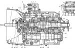
This is the original diagram from the article.

TTX: discharge current 50, 250, 500 mA, cut-off voltage 2.5-27.5 Volts.
I will list what did not like: the maximum discharge current is only 0.5A (and it’s not interesting to wait when 7 Ah is discharged), the cutoff range is too wide and it’s easy to knock it down, all the current goes to the start through the button, the current stabilizer on the field for the LED is too much, the diode in the control output increases the required drop on current resistors is up to 1.8V and in the event of a breakdown, 317 kayuk walkers.
About the discharge current: in batteries, it happens that the active mass is, as it were, sealed in a spread (not to be confused with sulfation), while the mobility of the electrolyte decreases and if it is discharged with a low current, it can give up the capacity completely, but when installed in a UPS, the test will not pass. Well, then you need to discharge it with a small current and charge it, i.e. treat.
The modularity of what I got is good in that you can make 2 or more discharge modules (you can 1 and switch current resistors) of different capacities or even types and 2 cutters for 6 and 12-volt batteries or 1 with a switch.
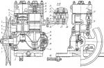
Pictures of my meter:

We see: a cut-off block, current load, Chinese clocks.
I repeat, I work as a sysadmin, sometimes I fix motherboards, so there is some dead iron slide.
I'll start in the reverse order: the walkers are slightly modified to run when powered from 1.5 to 25 volts.
Walker modification scheme:

1117 pulled from a dead motherboard.
A 2 kΩ resistor is the minimum load on the regulator.


accordingly the scheme:

It's 2 amps. Since R1 turned out to be more than 0.75 ohms, I had to add 2 resistances (this is R3, two in one in the photo) so that the current would be 2 amperes. If someone has not noticed, there are no gaskets between the micro with the transistor on the radiator. You can of course use another circuit, such as in radio 3/2007 p. 34, just add a reference voltage.
There is current and thermal protection in 317 (real).
Well, the scariest part is the cutter.


Super 3D-montage, but only 3 cm cubic, on the signet it will be much larger. Polevik, if on a 6V battery, then it is very desirable with logical control.
This part is almost the same as the original one, the start button has been moved from the drain-source to the collector-emitter, the variable has been replaced with a fixed divider, a Chinese super-bright LED through a resistor.
Possible variations: replace the upper shoulder (according to the original scheme, this is R4) with resistance + variable, thus limiting the setting range (required when the discharge current is commensurate with the battery capacity); other ideas are possible.
For formulas Uref=2.5v for regular 431, and for 431L it is 1.25v.
Fixed voltage cut-off:

Calculation formula: Uot = Uref(1+R4/R5)
or R5=(Ures-Uref)/(Uref*R4)
Voltage-adjustable cut-off:

Formula for calculation: Uots = Uref(1+(R4+R6)/R5)
or R5 = (Ures-Uref) / (Uref*(R4+R6))
But here it is necessary to count from the variable, on it, at a discharge of 0.1 s, (Udelta) 1.15v for 6v acb and 2.30v for 12v acb should fall.
Therefore, the formulas are converted and the calculation is somewhat different.
Umin see the table below.
R5 = Uref * R6 / Udelta
R4 = ((Umin -Uref) * R5) / Umin
A device with which you can check the capacity of lithium-ion AA batteries. Quite often, laptop batteries become unusable due to the fact that one or more batteries lose their capacity. As a result, you have to buy a new battery when you can get by with a little bloodshed and replace these worthless batteries.
What you need for the device:
Arduino Uno or any other compatible one.
16x2 LCD display using Hitachi HD44780 driver
Solid State Relay OPTO 22
Resistor 10 MΩ at 0.25 W
18650 battery holder
Resistor 4 ohm 6W
One button and power supply from 6 to 10V at 600 mA


Theory and operation
The voltage on a fully charged Li-Ion battery at no load is 4.2V. When a load is connected, the voltage rapidly drops to 3.9V, and then slowly decreases as the battery works. A cell is considered discharged when the voltage across it drops below 3V.
In this device, the battery is connected to one of the analog outputs of the Arduino. The voltage on the battery without load is measured and the controller waits for the “Start” button to be pressed. If the battery voltage is above 3V. , pressing the button will start the test. To do this, a 4 ohm resistor is connected to the battery through a solid state relay, which will act as a load. The voltage is read by the controller every half a second. Using Ohm's law, you can find out the current given to the load. I=U/R, U is read by the analog input of the controller, R=4 Ohm. Since measurements are taken every half second, 7200 measurements are obtained in each hour. The author simply multiplies 1/7200 of an hour by the current value, and adds the resulting numbers until the battery is discharged below 3V. At this moment, the relay switches and the display shows the measurement result in mAh
LCD pinout
PIN Purpose
1 GND
2 +5V
3 GND
4 Digital PIN 2
5 Digital PIN 3
6,7,8,9,10 No connected
11 Digital PIN 5
12 Digital PIN 6
13 Digital PIN 7
14 Digital PIN 8
15 +5V
16 GND


The author did not use a potentiometer to adjust the brightness of the display, instead he connected pin 3 to ground. The battery holder is connected negatively to ground and positively connected to analog input 0. A 10 MΩ resistor is connected between the plus of the holder and the analog input, which acts as a pull-up resistor. The solid state relay is turned on with a minus to the ground, and a plus to digital output 1. One of the relay's contact outputs is connected to the positive of the holder, a 4 ohm resistor is placed between the second output and the ground, which acts as a load when the battery is discharged. Keep in mind that it will get pretty hot. The button and switch are connected according to the diagram in the photo.

Since PIN 0 and PIN 1 are used in the scheme, they must be disabled before downloading the program to the controller.
After you connect everything, fill in the firmware attached below, you can try to test the battery.


The photo shows the voltage value that the controller considered.
The voltage on it must be higher than 3V.
This device is designed to measure the capacity of Li-ion and Ni-Mh batteries, as well as to charge Li-ion batteries with a choice of initial charge current.
Control
We connect the device to a stabilized power supply 5v and a current of 1A (for example, from a cell phone). The indicator displays the result of the previous capacitance measurement "ххххmA/c" for 2 seconds, and the value of the OCR1A register "S.xxx" is displayed on the second line. We insert the battery. If you need to charge the battery, then briefly press the CHARGE button, if you need to measure the capacity, then briefly press the TEST button. If you need to change the charge current (the value of the OCR1A register), then long (2 seconds) press the CHARGE button. We go to the window of register adjustment. We release the button. By briefly pressing the CHARGE button, we change the values \u200b\u200bof (50-75-100-125-150-175-200-225) of the register in a circle, the first line shows the charge current of an empty battery at the selected value (provided that you have a resistor 0 in your circuit .22 ohm). Briefly press the TEST button, the value of the OCR1A register is stored in non-volatile memory.
If you have done various manipulations with the device and you need to reset the clock, the measured capacity, then press the TEST button for a long time (the value of the OCR1A register is not reset). As soon as the charge is completed, the display backlight turns off, to turn on the backlight, briefly press the TEST or CHARGE button.
The logic of the device is as follows:
When power is applied, the indicator displays the result of the previous measurement of the battery capacity and the value of the OCR1A register stored in non-volatile memory. After 2 seconds, the device switches to the mode of determining the type of battery by the voltage value at the terminals.
If the voltage is more than 2V, then it is a Li-ion battery and the full discharge voltage will be 2.9V, otherwise it is a Ni-MH battery and the full discharge voltage will be 1V. Only after the battery is connected, the control buttons are available. Next, the device waits for the Test or Charge buttons to be pressed. The display shows "_STOP". By briefly pressing the Test button, the load is connected via the MOSFET.
The discharge current value is determined by the voltage across the 5.1 Ohm resistor and, every minute, is added to the previous value. The device uses 32768Hz quartz to operate the clock.
The display shows the current value of the battery capacity "ххххmA/c" and the discharge rate "А.ххх", as well as the time "хх:хх:хх" from the moment the button was pressed. An animated low battery icon is also shown. At the end of the test for the Ni-MH battery, the inscription "_STOP" appears, the measurement result is displayed on the display "ххххmA/c" and stored.

If the battery is Li-ion, then the measurement result is also displayed on the display "xxxxmA / c" and stored, but the charge mode immediately turns on. The display shows the contents of the OCR1A register "S.xxx". An animated battery icon is also shown.
The charge current is adjusted using PWM and is limited by a 0.22 Ohm resistor. Hardware charge current can be reduced by increasing the resistance of 0.22 ohm to 0.5-1 ohm. At the beginning of the charge, the current gradually increases to the value of the OCR1A register or until the voltage at the battery terminals reaches 4.22V (if the battery was charged).

The value of the charge current depends on the value of the register OCR1A - more value - more charge current. When the voltage at the battery terminals exceeds 4.22V, the value of the OCR1A register decreases. The recharging process continues until the value of the OCR1A register is 33, which corresponds to a current of about 40 mA. This completes the charge. The display backlight turns off.

Setting
1. Connect the power.
2. Connect the battery.
3. Connect the voltmeter to the battery.
4. Using the temporary buttons + and - (PB4 and PB5), we achieve the coincidence of the voltmeter readings on the display and on the reference voltmeter.
5. Long press the TEST button (2 seconds), memorization occurs.
6. Remove the battery.
7. We connect the voltmeter to the 5.1 Ohm resistor (according to the diagram near the 09N03LA transistor).
8. We connect an adjustable PSU to the battery terminals, set it to a 4V PSU.
9. Briefly press the TEST button.
10. We measure the voltage across the 5.1 Ohm resistor - U.
11. Calculate the discharge current I=U/5.1
12. Use the + and - time buttons (PB4 and PB5) to set the calculated discharge current I on the "A.xxx" indicator.
13. Long press the TEST button (2 seconds), memorization occurs. 
The device is powered by a stabilized source with a voltage of 5 volts and a current of 1A. Quartz at 32768Hz is designed for accurate timing. The ATmega8 controller is clocked from an internal 8 MHz oscillator, and it is also necessary to set the EEPROM erasure protection with the appropriate configuration bits. When writing the control program, training articles from this site were used.
The current values of the voltage and current coefficients (Ukof . Ikof) can be seen if you connect a 16x4 display (16x4 is preferred for debugging) on the third line. Or in Ponyprog if you open the EEPROM firmware file (read from the EEPROM controller).
1 byte - OCR1A , 2 bytes - I_kof, 3 bytes - U_kof, 4 and 5 bytes the result of the previous capacitance measurement.
 Video of the device operation: