Probably, any radio amateur is familiar with the microcircuit: a simple circuit, good sound quality, low price. Recently, I decided to take a look at the other side, again stumbling upon an article about Lincor's "MF-1" amplifier.
This is my first article, it is intended for beginner lovers of good sound. Also presented is a drawing of the PCB and a manufacturing option for the amplifier case.
My introduction didn't go very smoothly. At that time, there were a lot of fakes. They sometimes burned immediately at the first power supply, and if they did start, they did not give out a sound, but something remotely resembling it, because of which I wanted to douse the board with gasoline and set it on fire to get rid of this ULF and never remember about it. Maybe my inexperience was also the reason for this, or maybe the topology of the board of my own manufacture measuring 35 × 45 mm (when remembering that board, large-pimple goosebumps run through the author's body).
After reading, a decision was made to assemble according to the following criteria:
1) a clean ending without a volume control (the amplifier works in conjunction with a PC, and the sound is adjusted from it),
2) 2 amplification channels according to the double mono scheme (there were 2 transformers from UM Vega,
3) lower coefficient. channel penetration and beautiful stereo),
4) forced cooling with the help of 2 computer coolers and fans at low speeds,
5) and all this is mandatory in the case in the form of a finished structure, which is not ashamed to be posted on Datagor.

My version of PP
Strange as it may seem, the home-made amplifier of my neighbor, a former radio amateur, served as the case, assembled in the case of an unknown laboratory device. The amp was put on the landing, because. He was already unnecessarily, but it's a pity to throw it in the trash. I remembered this case when I decided to assemble the MF-1.
In the process of finalizing the hull, simple and inexpensive parts were used:
Aluminum corner 15 × 15 x 1 mm, bought at the Home Center.
M3 bolts with a countersunk head, nuts.
Metal spacers with M3 thread.
And here's what we got:

Transformers and filter

Rectifiers

Terminations with coolers
It's time for the panels. Because We have a fan for cooling, the air must come out somewhere and come in from somewhere. First of all, I started sawing the back panel with an air outlet:

Everything was done with a drill, electric jigsaw, engraver and needle files. Now we cut out the grille from the computer power supply case, clean the edges of the hole:


Now we take soldering acid, a soldering iron with a power of at least 100 W and solder the grate to the panel in several places:


We place input and output connectors on the panel, IT IS MANDATORY TO ISOLATE THEM FROM THE CASE:


We solder the shielding lead of the case to the panel. This will be the ONLY connection between the case and the common power wire. We connect the case to the ground contacts of the input connectors through 1-2 W resistors with a nominal value of 1.5-2 Ohm. These measures are needed in order not to grab the "earth loop", which will spoil us in the form of a 50 Hz background.

Back panel in place:

Now we transfer the Zobel circuit from the board to the PA output connectors. On the board, she does not quite have a place, because. it (the circuit) is a resonant system:

Now it's up to the front panel. It only has a power switch. The panel itself is made of aluminum, behind it is a false panel made of moderately soft plastic, on which you can fix anything with M3 screws with countersunk heads. I used the button from an old dead Wilma-104-Stereo cassette deck:


The panel is mounted on tin corners with hexagon bolts. That's it, the amplifier is ready!

Results
About the sound, I wrote a comment in the topic about:Guys, I didn't know! I didn't think I'd ever say this, but it's true! Pleasant soft bass, distinct highs (now I can distinguish percussion and hand claps on tracks I know by heart), and all this is a pleasure on homemade three-band TH with 8" woofers.
I want to reassure everyone who is repelled by an increased level of high frequencies: it does not feel like a rise in high frequencies, but as an increase in the quality of the source, an increase in “transparency”.
And I still do not go back on my words. For several months, the amplifier did not bother me at all, as it often happens with me. The sound is not annoying, I want to listen to everything and a lot, no matter at low or high volume.
By the way, about low volume. This ULF has a nice feature: at any volume level, the listener does not lack low frequencies, which can be compared with the use of TKRG, only with smooth (correct) adjustment and without blocking the midrange.
In my version, the board is slightly redone. The choice of "mute" and "standby" modes was thrown out as unnecessary, the main bank of capacitors was moved closer to the MS.
Power supply 2×23 V. KD213B diodes are used in the rectifier. Electrolytes are shunted with a capacity of 100 nF, transformer secondary - 47 nF.
Each MS is isolated from the heatsinks by a mica plate, the heatsinks are in turn grounded to the case.
All wires are twisted together to reduce interference.
The background is not audible even with an open input, even close to the speaker. The goal, so to speak, has been achieved!
Further, the plans are to drill holes for air intake in the right side of the bottom cover of the case, make a fan speed control device with control over the temperature of the radiators, it is possible to build in a preamplifier with a tone control, and paint the case.
Updated: 04/27/2016
An excellent amplifier for the home can be assembled on the TDA7294 chip. If you are not strong in electronics, then such an amplifier is ideal, it does not require fine tuning and debugging like a transistor amplifier and is easy to build, unlike a tube amplifier.
The TDA7294 chip has been produced for over 20 years and still has not lost its relevance, and is still in demand among radio amateurs. For a beginner radio amateur, this article will be a good help for getting to know integrated audio frequency amplifiers.
In this article I will try to describe in detail the amplifier device on the TDA7294. I will focus on a stereo amplifier assembled according to the usual scheme (1 microcircuit per channel) and briefly talk about the bridge circuit (2 microcircuits per channel).
Chip TDA7294 and its features
TDA7294 is the brainchild of SGS-THOMSON Microelectronics, this microcircuit is an AB class low frequency amplifier, and is built on field effect transistors.
Of the advantages of TDA7294, the following can be noted:
- output power, with distortion 0.3–0.8%:
- 70 W into 4 ohm load, typical circuit;
- 120 W into 8 ohm load, bridged;
- mute function (Mute) and standby function (Stand-By);
- low noise level, low distortion, frequency range 20–20000 Hz, wide operating voltage range - ±10–40 V.
Specifications
| Technical characteristics of the TDA7294 chip | |||||
|---|---|---|---|---|---|
| Parameter | Conditions | Minimum | Typical | Maximum | Units |
| Supply voltage | ±10 | ±40 | IN | ||
| Frequency response | Signal 3 db Output power 1W |
20-20000 | Hz | ||
| Long Term Output Power (RMS) | harmonic distortion 0.5%: Up \u003d ± 35 V, Rn \u003d 8 Ohm Up \u003d ± 31 V, Rn \u003d 6 Ohm Up \u003d ± 27 V, Rn \u003d 4 Ohm |
60 60 60 |
70 70 70 |
Tue | |
| Peak Musical Output Power (RMS), duration 1 sec. | harmonic factor 10%: Up \u003d ± 38 V, Rn \u003d 8 Ohm Up \u003d ± 33 V, Rn \u003d 6 Ohm Up \u003d ± 29 V, Rn \u003d 4 Ohm |
100 100 100 |
Tue | ||
| General harmonic distortion | Po = 5W; 1kHz Po = 0.1-50W; 20–20000Hz |
0,005 | 0,1 | % | |
| Up \u003d ± 27 V, Rn \u003d 4 Ohm: Po = 5W; 1kHz Po = 0.1-50W; 20–20000Hz |
0,01 | 0,1 | % | ||
| Protection operation temperature | 145 | °C | |||
| Quiescent current | 20 | 30 | 60 | mA | |
| Input impedance | 100 | kOhm | |||
| Voltage gain | 24 | 30 | 40 | dB | |
| Peak output current | 10 | A | |||
| Working temperature range | 0 | 70 | °C | ||
| Case thermal resistance | 1,5 | °C/W | |||
Pin assignment
| Pin assignment of the TDA7294 chip | |||
|---|---|---|---|
| Chip output | Designation | Purpose | Connection |
| 1 | Stby-GND | "Signal Ground" | "General" |
| 2 | In- | Inverting input | Feedback |
| 3 | In+ | Non-inverting input | Audio signal input via coupling capacitor |
| 4 | In+Mute | "Signal Ground" | "General" |
| 5 | N.C. | Not used | – |
| 6 | Bootstrap | "Voltage Boost" | Capacitor |
| 7 | +Vs | Input stage power (+) | |
| 8 | -Vs | Front stage power (-) | |
| 9 | Stby | Standby mode | Control block |
| 10 | Mute | Mute mode | |
| 11 | N.C. | Not used | – |
| 12 | N.C. | Not used | – |
| 13 | +PwVs | Output stage power (+) | Positive terminal (+) of the power supply |
| 14 | Out | Exit | Audio output |
| 15 | -PwVs | Output stage power (-) | Negative terminal (-) of the power supply |
Note. The microcircuit housing is connected to the power supply minus (pins 8 and 15). Don't forget to insulate the heatsink from the amplifier case, or isolate the chip from the heatsink by installing it through a thermal pad.
I also want to note that in my circuit (as well as in the datasheet) there is no separation of input and output "lands". Therefore, in the description and on the diagram, the definitions of “common”, “ground”, “case”, GND should be taken as concepts of the same sense.
Differences in hulls
The TDA7294 chip is available in two types - V (vertical) and HS (horizontal). TDA7294V, having a classic vertical design of the case, was the first to leave the assembly line and to this day is the most common and affordable.

Protection complex
The TDA7294 chip has a number of protections:
- protection against power surges;
- protection of the output stage against short circuit or overload;
- thermal protection. When the microcircuit is heated to 145 °C, the mute mode is activated, and at 150 °C, the standby mode (Stand-By) is activated;
- protection of microcircuit outputs from electrostatic discharges.
Power amplifier on TDA7294
A minimum of parts in the harness, a simple printed circuit board, patience and obviously good parts will allow you to easily assemble an inexpensive UMZCH on the TDA7294 with clear sound and good power for home use.
You can connect this amplifier directly to the line output of your computer's sound card. the nominal input voltage of the amplifier is 700 mV. And the nominal voltage level of the line output of the sound card is regulated within 0.7–2 V.
Structural diagram of the amplifier

The diagram shows a variant of a stereo amplifier. The structure of the amplifier in a bridge circuit is similar - there are also two boards with TDA7294.
- A0. power unit
- A1. Control unit for Mute and Stand-By modes
- A2. UMZCH (left channel)
- A3. UMZCH (right channel)
Pay attention to block connections. Improper wiring inside the amplifier can cause additional noise. To minimize noise as much as possible, follow a few rules:
- Power to each amplifier board must be supplied with a separate harness.
- Power wires must be twisted into a pigtail (bundle). This will compensate for the magnetic fields created by the current flowing through the conductors. We take three wires (“+”, “-”, “Common”) and weave a pigtail out of them with a slight tightness.
- Avoid ground loops. This is such a situation when a common conductor, connecting the blocks, forms a closed circuit (loop). The connection of the common wire must go in series from the input connectors to the volume control, from it to the UMZCH board and further to the output connectors. It is advisable to use connectors insulated from the body. And for the input circuits also shielded wires in isolation.
Parts list for PSU TDA7294:

When purchasing a transformer, note that the effective value of the voltage is written on it - U D, and by measuring with a voltmeter you will also see the effective value. At the output after the rectifier bridge, the capacitors are charged to the amplitude voltage - U A. The amplitude and effective voltages are related by the following relationship:
U A \u003d 1.41 × U D
According to the characteristics of TDA7294 for a load with a resistance of 4 ohms, the optimal supply voltage is ± 27 volts (U A). The output power at this voltage will be 70 watts. This is the optimal power for TDA7294 - the level of distortion will be 0.3-0.8%. There is no point in increasing power to increase power. the level of distortion grows like an avalanche (see graph).

We calculate the required voltage of each secondary winding of the transformer:
U D \u003d 27 ÷ 1.41 ≈ 19 V
I have a transformer with two secondary windings, with a voltage of 20 volts on each winding. Therefore, in the diagram, I designated the power terminals as ± 28 V.
To obtain 70 W per channel, taking into account the efficiency of the microcircuit 66%, we consider the power of the transformer:
P = 70 ÷ 0.66 ≈ 106 VA
Accordingly, for two TDA7294, this is 212 VA. The nearest standard transformer, with a margin, will be 250 VA.
Here it is appropriate to state that the power of the transformer is calculated for a pure sinusoidal signal, corrections are possible for a real musical sound. So, Igor Rogov claims that for a 50 W amplifier, a 60 VA transformer will be enough.
The high-voltage part of the PSU (before the transformer) is assembled on a 35 × 20 mm printed circuit board, it can also be surface mounted:

The low-voltage part (A0 according to the block diagram) is assembled on a 115 × 45 mm printed circuit board:

All amplifier boards are available in one.
This power supply for TDA7294 is designed for two microcircuits. For more chips, you will have to replace the diode bridge and increase the capacitance of the capacitors, which will entail a change in the dimensions of the board.
Control unit for Mute and Stand-By modes
The TDA7294 chip has a standby mode (Stand-By) and a mute mode (Mute). These functions are controlled through pins 9 and 10, respectively. The modes will be enabled as long as there is no voltage on these pins or it is less than +1.5 V. To “wake up” the microcircuit, it is enough to apply a voltage of more than +3.5 V to pins 9 and 10.
To simultaneously control all UMZCH boards (especially important for bridge circuits) and save radio components, it makes sense to assemble a separate control unit (A1 according to the block diagram):

Parts list for control box:
- Diode (VD1). 1N4001 or equivalent.
- Capacitors (C1, C2). Polar electrolytic, domestic K50-35 or imported, 47uF 25V.
- Resistors (R1-R4). Ordinary underpowered.
The printed circuit board of the block has dimensions of 35 × 32 mm:

The task of the control unit is to ensure silent switching on and off of the amplifier due to the Stand-By and Mute modes.
The principle of operation is the following. When the amplifier is turned on, along with the capacitors of the power supply, the capacitor C2 of the control unit is also charged. As soon as it is charged, the Stand-By mode will turn off. Capacitor C1 takes a little longer to charge, so the Mute mode will turn off in the second turn.
When the amplifier is disconnected from the network, the capacitor C1 is first discharged through the VD1 diode and turns on the Mute mode. Then the capacitor C2 is discharged and sets the Stand-By mode. The microcircuit becomes silent when the power supply capacitors have a charge of about 12 volts, so no clicks or other sounds are heard.
Amplifier on TDA7294 in the usual way
The circuit for switching on the microcircuit is non-inverting, the concept corresponds to the original one from the datasheet, only the component values have been changed to improve the sound characteristics.
Parts list:
- Capacitors:
- C1. Film, 0.33-1 uF.
- C2, C3. Electrolytic, 100-470uF 50V.
- C4, C5. Film, 0.68 uF 63 V.
- C6, C7. Electrolytic, 1000uF 50V.
- Resistors:
- R1. Variable dual with linear characteristic.
- R2-R4. Ordinary underpowered.
Resistor R1 is dual because stereo amplifier. Resistance not more than 50 kOhm with a linear, not a logarithmic characteristic for smooth volume control.
The R2C1 circuit is a high-pass filter (HPF), suppresses frequencies below 7 Hz, not passing them to the input of the amplifier. Resistors R2 and R4 must be equal to ensure stable operation of the amplifier.
Resistors R3 and R4 organize a negative feedback circuit (NFB) and set the gain:
Ku = R4 ÷ R3 = 22 ÷ 0.68 ≈ 32 dB
According to the datasheet, the gain should be in the range of 24-40 dB. If less, then the microcircuit will be self-excited, if more, distortion will increase.
Capacitor C2 is involved in the OOS circuit, it is better to take it with a larger capacitance in order to reduce its effect on low frequencies. Capacitor C3 provides an increase in the supply voltage of the output stages of the microcircuit - "voltage boost". Capacitors C4, C5 eliminate interference introduced by wires, and C6, C7 supplement the capacitance of the power supply filter. All capacitors of the amplifier, except for C1, must be with a voltage margin, so we take 50 V.
The printed circuit board of the amplifier is single-sided, rather compact - 55 × 70 mm. During its development, the goal was to breed the "earth" with a star, provide versatility and at the same time maintain minimal dimensions. I think this is one of the smallest boards for TDA7294. This board is designed for the installation of one chip. For the stereo version, respectively, you will need two boards. They can be installed side by side or one above the other like mine. I'll talk more about versatility a little later.

The radiator, as you can see, is indicated on one board, and the second, similar one, is attached to it from above. Photos will be a little further.
Amplifier on TDA7294 in a bridge circuit
A bridge circuit is a pairing of two conventional amplifiers with some amendments. Such a circuit solution is designed to connect acoustics with a resistance of not 4, but 8 ohms! Acoustics is connected between amplifier outputs.
There are only two differences from the usual scheme:
- the input capacitor C1 of the second amplifier is connected to ground;
- added feedback resistor (R5).
The printed circuit board is also a combination of amplifiers in the usual way. The board size is 110×70 mm.

Universal board for TDA7294
As you have already noticed, the above boards are essentially the same. The next PCB option fully confirms the versatility. On this board, you can assemble a 2x70W stereo amplifier (conventional circuit) or a 1x120W mono amplifier (bridged). The board size is 110×70 mm.


Note. To use this board in a bridge version, you must install the resistor R5, and install the jumper S1 in a horizontal position. In the figure, these elements are shown by dotted lines.
For a conventional circuit, resistor R5 is not needed, and the jumper must be installed in a vertical position.
Assembly and adjustment
Assembling the amplifier will not cause any particular difficulties. As such, the amplifier does not require adjustment and will work immediately, provided that everything is assembled correctly and the microcircuit is not defective.
Before first use:
- Make sure the radio components are installed correctly.
- Check the correct connection of the power wires, do not forget that on my amplifier board the "ground" is not in the center between plus and minus, but on the edge.
- Make sure the chips are isolated from the heatsink, if not, then check that the heatsink is not in contact with ground.
- Apply power to each amplifier in turn, so there is a chance not to burn all the TDA7294 at once.
First power on:
- We do not connect the load (acoustics).
- We close the inputs of the amplifiers to the "ground" (close X1 with X2 on the amplifier board).
- We serve food. If everything is fine with the fuses in the PSU and nothing smoked, then the launch was a success.
- With a multimeter, we check the absence of direct and alternating voltage at the output of the amplifier. A slight constant voltage is allowed, not more than ± 0.05 volts.
- We turn off the power and check the microcircuit case for heating. Be careful, the capacitors in the PSU are discharged for a long time.
- Through a variable resistor (R1 according to the diagram), we give a sound signal. We turn on the amplifier. The sound should appear with a slight delay, and immediately disappear when turned off, this characterizes the operation of the control unit (A1).
Conclusion
I hope this article will help you build a high-quality amplifier on the TDA7294. Finally, I present a few photos during the assembly process, do not pay attention to the quality of the board, the old textolite was unevenly etched. As a result of the assembly, some edits were made, so the boards in the .lay file are slightly different from the boards in the photographs.


The amplifier was made for a good friend, he came up with and implemented such an original case. Photos of the stereo amplifier on the TDA7294 assembly:


On a note: All printed circuit boards are collected in one file. To switch between "seals" click on the tabs as shown in the figure.

list of files
Pretty simple. Even a person who is not very strong in electrical engineering can repeat it. ULF on this chip will be ideal for use as part of a speaker system for a home computer, TV, cinema. Its advantage is that fine tuning and tuning is not required, as is the case with transistor amplifiers. And what can we say about the difference from lamp structures - the dimensions are much smaller.
No high voltage is required to power the anode circuits. Of course, there is heating, as in lamp designs. Therefore, if you plan to use the amplifier for a long time, it is best to install, in addition to an aluminum radiator, at least a small fan for forced airflow. Without it, on the TDA7294 microassembly, the amplifier circuit will work, but there is a high probability of switching to temperature protection.
Why TDA7294?
This chip has been very popular for over 20 years. It has won the trust of radio amateurs, since it has very high characteristics, amplifiers based on it are simple, anyone, even a beginner radio amateur, can repeat the design. The amplifier on the TDA7294 chip (the diagram is given in the article) can be either monophonic or stereophonic. The internal device of the microcircuit consists of an audio frequency amplifier built on this microcircuit belongs to class AB.
Advantages of the microcircuit
Benefits of using a microchip for:
1. Very high output power. About 70 W if the load has a resistance of 4 ohms. In this case, the usual scheme for switching on the microcircuit is used.
2. Approximately 120W into 8 ohms (bridged).
3. A very low level of extraneous noise, insignificant distortion, reproducible frequencies lie in the range that is completely perceived by the human ear - from 20 Hz to 20 kHz.
4. The microcircuit can be powered from a constant voltage source of 10-40 V. But there is a small drawback - you must use a bipolar power supply.
It is worth paying attention to one feature - the distortion factor does not exceed 1%. On the TDA7294 microassembly, the power amplifier circuit is so simple that it is even surprising how it allows you to get such high-quality sound.
The purpose of the pins of the microcircuit

And now in more detail about what conclusions the TDA7294 has. The first leg is the “signal ground”, it is connected to the common wire of the entire structure. Conclusions "2" and "3" - inverting and non-inverting inputs, respectively. The "4" pin is also a "signal ground" connected to ground. The fifth leg is not used in audio frequency amplifiers. The "6" leg is a volt additive, an electrolytic capacitor is connected to it. "7" and "8" conclusions - plus and minus the power supply of the input stages, respectively. Leg "9" - standby mode, used in the control unit.
Similarly: "10" leg - mute mode, also used when designing an amplifier. "11" and "12" conclusions are not used in the design of audio frequency amplifiers. From the "14" output, the output signal is taken and fed to the speaker system. "13" and "15" pins of the microcircuit are "+" and "-" for connecting the power supply of the output stage. On the TDA7294 chip, the circuit is no different from those proposed in the article, it is only supplemented by which it is connected to the input.
Features of microassembly

When designing an audio frequency amplifier, you need to pay attention to one feature - the power minus, and these are the legs "15" and "8", electrically connected to the microcircuit case. Therefore, it is necessary to isolate it from the heat sink, which in any case will be used in the amplifier. For this purpose it is necessary to use a special thermal pad. If you use a bridge amplifier circuit on the TDA7294, pay attention to the version of the case. It can be vertical or horizontal type. The most common is the version designated as TDA7294V.
Protective functions of the TDA7294 chip

The microcircuit provides several types of protection, in particular, against a drop in the supply voltage. If the supply voltage suddenly changes, the microcircuit will go into protection mode, therefore, there will be no electrical damage. The output stage is also protected against overloads and short circuits. If the body of the device heats up to a temperature of 145 degrees, the sound is turned off. When it reaches 150 degrees, it goes into standby mode. All pins of the TDA7294 chip are protected from electrostatics.
Amplifier
Simple, accessible to everyone, and most importantly - cheap. In just a few hours, you can assemble a very good audio frequency amplifier. And most of the time you will spend on etching the board. The structure of the entire amplifier consists of power and control units, as well as 2 ULF channels. Try to use as few wires as possible in the design of the amplifier. Follow these simple guidelines:
1. A prerequisite is the connection of a power source by wires to each UZCH board.
2. Bundle the power wires. With this, it will be possible to slightly compensate for the magnetic field that is created by the electric current. To do this, you need to take all three supply wires - “common”, “minus” and “plus”, with a slight tension weave them into one pigtail.
3. In no case do not use the so-called "earth loops" in the construction. This is the case when a common wire connecting all blocks of the structure closes in a loop. The ground wire must be connected in series, starting from the input further to the UZCH board, and must end at the output connectors. It is extremely important to connect the input circuits with shielded wires in isolation.
Standby and mute control unit

This chip also has muting. It is necessary to control the functions using the conclusions "9" and "10". The mode is turned on if there is no voltage on these legs of the microcircuit, or it is less than one and a half volts. To enable the mode, it is necessary to apply a voltage to the microcircuit legs, the value of which exceeds 3.5 V. In order for the amplifier boards to be controlled simultaneously, which is important for bridge-type circuits, one control unit is assembled for all cascades.
When the amplifier turns on, all the capacitors in the power supply are charged. In the control unit, one capacitor also accumulates a charge. When the maximum possible charge is accumulated, the standby mode is turned off. The second capacitor used in the control unit is responsible for the operation of the mute mode. It charges a little later, so the mute mode is disabled second.
Hi-Fi class low-frequency power amplifier, made in a bridge circuit using two TDA7294 integrated circuits. Allows you to get up to 170 watts of output power, perfect for a subwoofer.
Specifications
- Output power at a load of 8 ohms and a supply of ± 25V - 150 W;
- Output power at a load of 16 ohms and a supply of ± 35V - 170 W.
circuit diagram
The amplifier provides output stage short-circuit protection, thermal protection (switching to reduced power in case of overheating that occurs under heavy loads), surge protection, standby mode, input on / off mode (Mute), and protection from the "click" when turning on / off. All this has already been implemented in TDA7294 integrated circuits.
Rice. 1. The bridge circuit for switching on two TDA7294 microcircuits is a powerful LF bridge amplifier.
Parts and circuit board

Rice. 2. Printed circuit board for the bridge version of the inclusion of TDA7294 microcircuits.
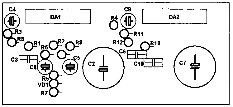
Rice. 3. The location of the components for the bridge version of the inclusion of TDA7294 microcircuits.
To power such a power amplifier, a power supply with a transformer with a power of at least 250-300 watts is required. In the rectifier circuit, it is desirable to install electrolytic capacitors of 10,000 microfarads or more on each arm.
Bridge switching circuit from the datasheet

Rice. 4. Bridge circuit for switching on two TDA7294 microcircuits (from the datasheet).
In bridge mode, the load resistance must be at least 8 ohms, otherwise the microcircuits will burn out from overcurrent!
Printed circuit board
Universal printed circuit board for two-channel and bridge versions of the power amplifier.
The UMZCH bridge switching circuit is two identical channels, in one of which the signal input is connected to ground, and the feedback input (leg 2) is connected through a 22K resistor to the output of the second channel.
Also, the 10th legs of the microcircuits (Mute) and the 9th legs (Stand-By) must be connected to the mode control circuit assembled on resistors and capacitors (Figure 6).

Rice. 5. Printed circuit board for a power amplifier based on TDA7294 chips.
The boards have slight deviations (for the better) from the scheme from the datasheet:
- At the inputs of the microcircuits (leg 3), capacitors are installed at 4 microfarads, and not 0.56 microfarads;
- A 470uF capacitor is connected between the 680 ohm resistor (which goes to pin 2) and ground;
- Capacitors between legs 6 and 14 - 470uF, not 22uF;
- For power supply, instead of 0.22 μF capacitors, it was proposed to install 680 nF (0.68 μF);
In bridging, pins 10 and 9 are connected together, respectively, and connected to the mode control circuit.

Rice. 6. A simple control scheme for Standby-Mute modes for TDA7294 microcircuits.
To turn on the microcircuits (out of the quiet and power-saving modes), it is enough to connect the "VM" and "VSTBY" contacts to the +Vs positive power output.
This printed circuit board is universal, it can be used for both dual-channel and bridged modes of operation of the amplifier on TDA7294 microcircuits. The ground wiring (GND) is very well done here, which will improve the reliability and noise immunity of the UMZCH.
Literature:
- Datasheet for the TDA7294 chip - Download (7-Zip archive, 1.2MB).
- FAQ on TDA7294 - cxem.net/sound/amps/amp129.php
A low frequency amplifier (ULF) is such a device for amplifying electrical oscillations corresponding to the frequency range audible to the human ear, i.e. ULF should amplify in the frequency range from 20 Hz to 20 kHz, but some ULF can have a range up to 200 kHz. ULF can be assembled as an independent device, or used in more complex devices - TVs, radios, radios, etc.
The peculiarity of this circuit is that the 11th output of the TDA1552 microcircuit controls the operating modes - Normal or MUTE.

C1, C2 - bypass blocking capacitors, used to cut off the constant component of the sinusoidal signal. Electrolytic capacitors should not be used. It is desirable to place the TDA1552 chip on a heatsink using heat-conducting paste.
In principle, the presented circuits are bridge circuits, since there are 4 amplification channels in one TDA1558Q microassembly case, therefore pins 1 - 2, and 16 - 17 are connected in pairs, and they receive input signals from both channels through capacitors C1 and C2. But if you need an amplifier for four speakers, then you can use the circuit option below, although the power will be 2 times less per channel.
The basis of the design is the TDA1560Q class H microassembly. The maximum power of such a ULF reaches 40 W, with a load of 8 ohms. Such power is provided by an approximately doubled voltage due to the operation of the capacitors.

The output power of the amplifier in the first circuit assembled on the TDA2030 is 60W at a load of 4 ohms and 80W at a load of 2 ohms; TDA2030A 80W at 4 ohm load and 120W at 2 ohm load. The second circuit of the considered ULF is already with an output power of 14 watts.

This is a typical two-channel ULF. With a little piping of passive radio components on this chip, you can assemble an excellent stereo amplifier with an output power of 1 watt per channel.
Microassembly TDA7265 - is a fairly powerful two-channel Hi-Fi class AB amplifier in a typical Multiwatt package, the microcircuit has found its niche in high-quality stereo technology, Hi-Fi class. Simple switching circuits and excellent parameters made the TDA7265 a perfectly balanced and excellent solution for building high-quality amateur radio equipment.
First, a test version was assembled on a breadboard exactly as per the datasheet on the link above, and successfully tested on S90 speakers. The sound is good, but something was missing. After some time, I decided to remake the amplifier according to the modified circuit.
The Micro Assembly is a class AB quad amplifier designed specifically for use in automotive audio applications. Based on this microcircuit, several high-quality ULF variants can be built using a minimum of radio components. The microcircuit can be advised to beginner radio amateurs for home assembly of various acoustic systems.
The main advantage of the amplifier circuit on this microassembly is the presence of four independent channels in it. This power amplifier works in AB mode. It can be used to amplify various stereo signals. If desired, you can connect to the speaker system of a car or a personal computer.
TDA8560Q is just a more powerful analogue of the TDA1557Q chip, widely known to radio amateurs. The developers only strengthened the output stage, thanks to which the ULF is perfect for a two-ohm load.
The LM386 micro-assembly is a ready-made power amplifier that can be used in low-voltage designs. For example, when the circuit is powered by a battery. LM386 has a voltage gain of about 20. But by connecting external resistances and capacitances, you can adjust the gain up to 200, and the output voltage automatically becomes equal to half the supply voltage.
The LM3886 micro-assembly is a high quality amplifier with an output of 68 watts into 4 ohms or 50 watts into 8 ohms. At the peak moment, the output power can reach a value of 135 watts. A wide voltage range from 20 to 94 volts is applicable to the microcircuit. Moreover, you can use both bipolar and unipolar power supplies. The ULF harmonic coefficient is 0.03%. Moreover, this is over the entire frequency range from 20 to 20,000 Hz.

The circuit uses two ICs in a typical connection - KR548UH1 as a microphone amplifier (installed in the PTT) and (TDA2005) in bridge connection as a terminal amplifier (installed in the siren case instead of the original board). As an acoustic emitter, a modified alarm sipen with a magnetic head is used (piezo emitters are not suitable). Improvement consists in disassembling the siren and throwing out the native tweeter with an amplifier. Microphone - electrodynamic. When using an electret microphone (for example, from Chinese handsets), the connection point of the microphone with the capacitor must be connected to + 12V through a resistor ~ 4.7K (after the button!). The 100K resistor in the K548UH1 feedback circuit is better to put with a resistance of ~ 30-47K. This resistor is used to adjust the volume. It is better to install the TDA2004 chip on a small radiator.
To test and operate - with a radiator under the hood, and a tangent in the cabin. Otherwise, squealing due to self-excitation is inevitable. The trimmer resistor sets the volume level so that there is no strong sound distortion and self-excitation. With insufficient volume (for example, a bad microphone) and a clear margin of power of the emitter, you can increase the gain of the microphone amplifier by increasing the value of the trimmer in the feedback circuit several times (the one that is 100K according to the scheme). In a good way - we would need another primambas that does not allow the circuit to self-excite - some kind of phase-shifting chain or a filter for the excitation frequency. Although the scheme and without complications works fine