The vacuum brake booster appeared on mass-produced cars back in the 50s and 60s of the last century and made it possible to significantly lighten the effort on the brake pedal and the effectiveness of the brakes. This article will describe in detail the device and principle of operation of a vacuum amplifier, knowledge of which will greatly help even novice drivers to independently identify and eliminate the most common amplifier malfunctions, which will also be described in this article (and how to fix them).
The vacuum booster serves to reduce the force that the driver applies to the brake pedal, thereby making it easier to control the machine and increase the effectiveness of the brakes. The amplifier is located in the engine compartment (engine compartment) of the car and is attached with a rear flange to the pedal bracket and the partition separating the engine compartment from the passenger compartment.
Next, the device of the VAZ vacuum brake booster will be described in detail, which is quite common and does not differ much in design from the amplifiers of other cars, including foreign cars. The principle of operation for many amplifiers of different machines is the same, with the exception of some little things.
The operation of the brake booster is, of course, possible when the engine of the car is running, that is, when air is created in the intake manifold of the engine, but about the operation of the amplifier a little later, but first we will consider its device, knowledge of which will allow beginners to better understand the principle of operation and possible problems.
VAZ brake booster device .
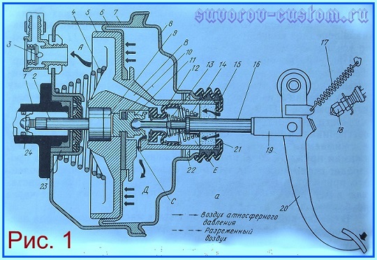
Figure 1 - vacuum booster at the moment of braking. 1 - master cylinder, 2 - rod, 3 - vacuum valve, 4 - return spring, 5 - valve body, 6 - diaphragm, 7 - booster housing, 8 - booster cover, 9 - rod buffer, 10 - piston thrust plate, 11 - piston, 12 - booster valve, 13 - valve spring, 14 - valve return spring, 15 - air filter, 16 - pusher, 17 - return spring, 18 - stoplight switch tip, 19 - pusher fork, 20 - brake pedal, 21 - boot, 22 - cuff, 23 - sealant, 24 - adjusting bolt.
The vacuum brake booster consists of a body 7 (see Figure 1) of a cover 8 and a valve body 5 with a diaphragm 6. Thanks to the body 5 and the rubber diaphragm 6, the booster is divided into two cavities, one of which is vacuum A, and the second is atmospheric D. In addition the valve body 5 not only divides the amplifier into two cavities, but also acts as a large piston that moves in the common body 7.
On most cars, the valve body 5 is made of plastic and has a through hole from which channels B and C extend. The channel marked B in the figure connects the central hole to the vacuum cavity, and channel C connects the central hole to the atmospheric cavity.
The pusher 16 enters the center of the valve body 5, which is pivotally connected to the brake pedal 20 through the fork 19. The front end of the pusher has a ball tip, which is fixed in the piston 11.
The longitudinal movement of the piston 11 relative to the valve body is limited by the thrust plate 10, which is fixedly fixed in the valve body and which enters the annular groove in the piston. And the piston width is slightly larger than the plate.
The annular gap between the valve body 5 and the neck of the cover 8 is sealed with a cuff 22, which must be in good condition. And the surface of the valve body must be lubricated with grease (Litol 24 or TsIATIM-221).
From the ingress of dust and dirt, the neck of the cover 8 is protected by a rubber corrugated anther 21 (of course, this anther should not have cracks, and even more so gaps). Also, a filter 15 is installed around the pusher for cleaning the air entering the cavity of the amplifier and the support cups of the springs, the springs themselves 13 and 14 and the rubber valve 12 are also installed.
In front of the body 7 of the vacuum booster, at the outlet of the rod 2, a seal 23 is inserted. And at the end of the rod 2 there is an adjusting bolt 24, which, when the machine is braked, rests against the seat in the piston 1. With its rear part, the rod 2 rests against the rubber buffer 9, which is installed between the rod and piston 11.
In the absence of vacuum or mechanical action, the return spring 4 moves the valve body 5 to the extreme right position. And the vacuum cavity A is connected by a hose to the internal cavity of the engine intake manifold through a fitting in which the check valve 3 is located. This check valve opens when the pressure difference between the cavity A of the amplifier and the engine intake manifold.
As mentioned above, the operability of the amplifier is possible only when the engine of the machine is running, when there is an air vacuum in the intake manifold, which is transmitted to cavity A.
Operation of the vacuum brake booster .
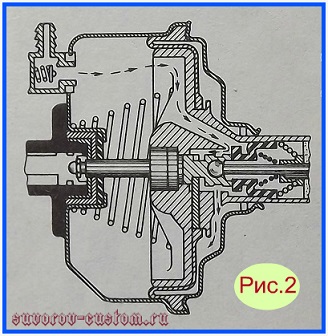
Figure 2. Vacuum booster when the brake pedal is not depressed.
The principle of operation of the vacuum amplifier is based on the pressure difference in the vacuum and atmospheric chambers. And the pressure created in the vacuum chamber moves the rod and presses on the piston of the main brake cylinder, thereby making it easier for the driver to press on the brake pedal. The principle of operation was briefly described above, and if it is much more detailed, then we read further.
The operation of the amplifier is as follows: with the brake pedal lowered (see Figure 2), the vacuum cavity A, through channels C and B, communicates with the atmosphere of the cavity D, using an annular slot between the front end of the valve 12 and the annular protrusion of the valve body 5 located in front of it.
At the same time, the atmospheric cavity D is isolated from the atmosphere by the end of the rubber valve 12, which, due to the force of the spring 13, is pressed against the rear end of the piston 11. And at the same time, there is a vacuum on both sides of the diaphragm, and the diaphragm and the valve body are pressed against the cover 8 of the amplifier housing under the action of the spring 4 .
When the car brakes, the pusher 16, together with the piston 11 and the movable part of the rubber valve 12 pressed against it, moves forward until the annular gap disappears and the end of the valve 12 rests against the annular protrusion of the valve body 5. In this case, the vacuum cavity A will be isolated from the atmospheric cavity D.
During braking, further movement of the brake pedal 20 and its pusher 16 will move the piston 11 away from the valve 12 (as shown in Figure 1) and this will lead to the formation of an annular gap between them and air will go into the atmospheric cavity D from the cavity E, which is connected to the atmosphere through a vortex air filter 15.
Due to the pressure difference, the valve body 5 and the diaphragm 6 will begin to move forward, from this the head of the adjusting bolt 24 of the stem 2 will begin to put pressure on the piston of the brake master cylinder. In this case, the piston will create excess pressure in the hydraulic brake system of the car.
![]()
Figure 3. Operation of the vacuum booster when the brake pedal is depressed.
When the brake pedal stops moving forward (see Figure 3), due to the vacuum in cavity A, the valve body 5, together with the rubber valve 12 pressed against it, will move forward until the valve 12 rests against the rear end of the piston 11. From this, the communication between the cavity D and the cavity E will stop, as well as the movement of the valve body 5 will stop.
In this case, equilibrium will be established and the brake fluid in the hydraulic brake system will be under constant pressure.
In the event of emergency braking of the machine, the piston 11 will rest through the rubber buffer 9 against the rod 2 and begin to mechanically act on the piston of the main brake cylinder. In addition, the piston 11, moving away from the valve 12, will ensure its stop in the annular protrusion of the valve body 5. This will lead to the separation of the cavity D and the cavity A and communication of the cavity D with the atmosphere, and this will increase the pressure created in the hydraulic brake system.
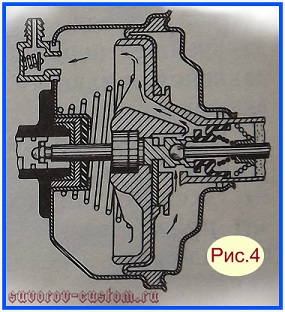
Figure 4. Vacuum booster operation when the driver releases the brake pedal (braking occurs)
When the braking of the machine is no longer required and the driver releases the brake pedal, the moving parts of the drive will return back to their initial position (as in Figure 4) from the action of the return spring 17 of the brake pedal and from the action of the return spring 4 of the vacuum brake booster, well, from the action of the return springs of the main brake cylinder.
In this case, the piston 11 will press the valve 12 from the annular protrusion of the valve body 5 and at the same time an annular gap is formed through which air will begin to flow through channels B and C from cavity D into cavity A and, at the same time, be sucked out by vacuum in the engine intake manifold. In this case, the communication of the cavity D with the cavity E will stop, since the end of the valve 12 is pressed against the piston 11 by the force of the spring 13.
When the car's engine is not running (or if the vacuum brake booster is faulty), the car can be braked, but the brake pedal travel will increase slightly and the brake efficiency will decrease. In this case, the drive of the pistons of the main brake cylinder will be carried out only mechanically, from the brake pedal through the pusher 16, the piston 11, the rubber buffer 9 and the rod 2.
The main malfunctions and repair of the vacuum amplifier .
Like any mechanism, a vacuum booster, or rather its parts, wear out over time and require replacement, maintenance, or repair. A hint to the driver that something is wrong with the vacuum booster will be an increase in the force applied to the brake pedal and a decrease in braking efficiency.
A decrease in braking efficiency, of course, can also occur for other reasons, for example, due to a malfunction of the calipers (I advise you to read more about their restoration) or for other reasons described in the article “The brake system, its structure and malfunctions” (the article is located), but here an increase in effort on the brake pedal is a sure sign of a malfunctioning vacuum booster.
A common cause of amplifier failure that appears over time, especially if the car often drives on dusty roads, is clogging of the air filter 15 with dirt or dust (see figure 1). A dirty filter should be washed, dried, or replaced with a new one.
And with a sufficiently large mileage of the car, malfunctions may occur due to jamming of the valve body 5 from swelling (from old age) of the diaphragm 6. Also, malfunctions may occur due to loose fastening of the vacuum hose that connects the vacuum brake booster to the intake manifold fitting of the engine. Or, due to the aging of the hose, cracks or breaks appear on it.
It is quite easy to identify cracks or breaks visually, or you can hear it by a characteristic hiss (air leak). By the way, with such a malfunction (leakage or damage to the hose), the car’s engine usually works intermittently, or loses power, as excess air enters the intake manifold and the combustible mixture becomes depleted in all engine operating modes.
Well, an even less common malfunction that can occur with careless care or from the use of low-quality (fake and cheap) brake fluid, or due to gasoline or oil getting into the brake fluid, is swelling of the seals of the hydraulic cylinders of the brake system. And there is a jamming of moving parts in hydraulic cylinders.
To identify a malfunction, you should flush the air filter (if it is dirty), check the operation of the crankcase ventilation system (I wrote how to improve it), replace the vacuum hose if it is swollen or has cracks, and even more so breaks, and securely fasten the vacuum hose with a new clamp (preferably a stronger one made of stainless steel).
In case of stem sticking, the brake master cylinder should be disassembled and the swollen cuffs replaced with new ones. With such a malfunction (swelling of the seals), before replacing the rubber bands, it is imperative to flush the entire brake system with isopropyl alcohol (if it is not there, then rinse with fresh brake fluid of the same brand that will be used in the system). After flushing the system and installing new cuffs, fill in fresh brake fluid and.
If after carrying out the work described above, the malfunction is not eliminated (the force on the brake pedal, with the engine running, remains as heavy as with the engine turned off), then most likely the cause of the malfunction is a swollen or torn diaphragm 6.
Replacing the diaphragm with a new one is not so easy, since most amplifiers have a non-separable case (cover 8 is rolled to body 7), and it is not always possible to buy a new diaphragm. In this case, the vacuum brake booster must be replaced.
You can check the serviceability of the vacuum booster not only by reducing the effort on the brake pedal with the engine running, but also in another way. With the engine off, press the brake pedal with a little effort, then start the engine. After the engine has started, if the brake pedal goes forward a little (fails a little), then everything is in order with the vacuum booster.
And the last thing: on the vacuum booster and the main brake cylinder adjacent to it, there should be no fogging, and even more so no leakage of brake fluid. You can find out exactly where it is leaking from if you thoroughly wash the body of the amplifier and the main brake cylinder and then start the engine and press the brake pedal several times. After that, leaks are usually detected immediately, and, of course, bad seals should be replaced with new ones.
That seems to be all, I hope this article will help novice drivers to determine the malfunction of the vacuum brake booster and eliminate most of its malfunctions, success to everyone.