Toyota Timing Belt Replacement
Removing and installing timing belt Toyota(engines series A). 1 - high voltage wires, 2 - power steering pump drive belt, 3 - coolant pump pulley, 4 - wiring harness protection, 5 - wiring harness, 6 - washer reservoir, 7 - right engine support, 8 - oil filler cap, 9 - hoses of the crankcase ventilation system, 10 - sealing washer, 11 - cylinder head cover, 12 - gasket, 13 - timing belt, 14 - timing belt cover No. 3, 15 - tensioner roller spring, 16 - air conditioning compressor bracket, 1.7 - air conditioning compressor, 18 - right side of the engine protection, 19 - air conditioning compressor drive belt, 20 - generator drive belt, 21 - crankshaft pulley, 22 - timing belt cover No. 1, 23 - timing belt guide, 24 - cover timing belt No. 2, 25 - CPS sensor.
1. Disconnect the negative plug from the storage battery.
2. Remove the right side of the engine protection.
3. Loosen the coolant pump pulley bolt.
4. Remove the alternator drive belt.
A) Loosen the pinch bolt.

5. Remove the A/C compressor drive belt.
6. Remove the washer reservoir.
7. Remove the power steering pump drive belt.
A) Loosen the pinch bolt.
B) Loosen the adjusting bolt and remove the belt.

8. Remove the harness guard and disconnect the harness.
9. Disconnect high voltage wires.
10. Disconnect the crankcase ventilation hoses.
11. Remove the cylinder head cover.
12. Remove timing belt cover #3.
13. (4A-FE, 7A-FE) Disconnect the combustion chamber pressure sensor wire.
14. Remove the air conditioning compressor by disconnecting the electromagnetic clutch connector, hose and unscrewing the 4 mounting bolts.

15. Remove the compressor bracket by unscrewing the 4 mounting bolts.
16. Turn away 4 bolts and remove a pulley of the pump of a cooling liquid.
17. Remove timing belt cover #2.
18. Set the piston of the first cylinder to the TDC of the end of the compression stroke.
A) Rotate the crankshaft pulley and align the groove on the pulley with the "O" mark on the #1 timing belt guard.

6) Make sure that the hole in the camshaft drive pulley is aligned with the mark on its bearing cap.
Otherwise turn the crankshaft one revolution (360°).
19. Remove the crankshaft pulley,
A) Using a suitable tool, remove the pulley fixing bolt.

b) Using a puller, remove (compress) the crankshaft pulley.
20. Remove timing belt cover #1.
21. Remove the timing belt guide.

23. Disconnect the right engine mount by unscrewing 3 bolts and 3 fastening nuts.
24. Remove the timing belt.
In case of reusing the belt, draw an arrow in the direction of the belt (in the direction of rotation of the engine crankshaft) and make marks on the belt and pulleys as shown in the figures.
A) Loosen the tensioner roller mounting bolt, move it all the way to the left and then temporarily fix it in this position with the same mounting bolt.

b) Remove the timing belt
25. Remove the tension roller and tension spring by completely unscrewing the tension roller mounting bolt.
26. If necessary, remove the crankshaft sprocket. In case of difficulty, use 2 screwdrivers. Note: to prevent damage to the elements of the cylinder block, place a rag

30. If necessary, remove a gear pulley of a camshaft. Holding the camshaft from turning, setting the adjustable wrench on its hex part, unscrew the fixing bolt and remove the pulley.
Timing belt installation for Toyota A series engines 5a - fe, 4a - fe, 7a - fe,
Keep water and oil away from the camshaft and crankshaft pulleys and keep them clean.
1. Install the camshaft sprocket (if removed).
A) Align the dowel pin on the camshaft nose with the toothed pulley groove and fit the pulley onto the camshaft.

b) Temporarily install the pulley bolt.
C) Holding the camshaft by its hex part with a wrench, tighten the camshaft pulley bolt.
Tightening torque.......................59 Nm
2. Install the crankshaft sprocket (if removed).
A) Align the key on the crankshaft with the keyway of the toothed pulley.
B) Push the pulley onto the toe of the crankshaft until it stops with the flare inward.

3. Temporarily install the roller tensioner with spring.
A) Fix the roller with the bolt without tightening it.
b) Install the spring.
B) Pull the roller to the left until it stops and tighten the bolt;
4. Install the timing belt.
Engine 5A-FE
A) Set the piston of the 1st cylinder to the BMI position at the end of the compression stroke.

Using the crankshaft sprocket bolt, turn the crankshaft 'and align the timing marks on the sprocket and on the oil pump housing

Warning: The engine must be cold.
Note: If the belt is to be reused, align the previously made marks on the pulleys and the belt, and take into account the direction of rotation of the belt.
Install the timing belt, observing the marks and providing the necessary tension in the area between the toothed pulleys of the crankshaft and camshaft.
Slowly loosen the idler pulley bolt.

- Slowly turn the crankshaft 2 turns clockwise from TDC to TDC after installing the toothed pulley mounting bolt.
Make sure the timing marks on each pulley align with the timing marks on the oil pump housing (for > crankshaft pulley) and on the camshaft bearing cap as shown in the illustration
Tightening torque ........................38 N.m
D) Install the toothed belt guide with the flare outward, as shown in the figure.

e) Install protective cap #1.
Bolt tightening torque ........... 8 N.m
Engine 4A-FE
A) Set the piston of the 1st cylinder to the TDC position at the end of the compression stroke.
With an adjustable wrench on the hex section of the camshaft, turn it and align the mark on the camshaft bearing cap with the center of the small hole on the camshaft pulley.

- Temporarily install the timing belt.
Install the timing belt guide with the right side facing out.
Install timing belt cover #1.

- Install the crankshaft pulley.
Turn the crankshaft pulley and align it with the alignment mark "O" on the cover No. 1 of the timing belt.
b) Install the timing belt.
The engine must be cold.
If the belt is to be reused, align the previously marked marks on the pulleys and the belt, and take into account the direction of rotation of the belt.
Install the timing belt, observing the marks and providing the necessary tension in the area between the toothed pulleys of the crankshaft and camshaft,
B) Check the correct installation of the belt (camshaft timing).
Slowly loosen the idler pulley bolt

Slowly turn the crankshaft 2 turns clockwise from TDC to TDC after installing the toothed pulley mounting bolt.
Make sure the timing marks on each pulley align with their respective timing marks as shown.
Tighten the tensioner pulley bolt.

Tightening torque .............. 38 N m
5. Install the right engine mount by tightening the 3 bolts and 3 fastening nuts.
Torque:
Nut.........................................53 N.m
Bolt.......................................74 Nm
6. Lower the engine with a hoist.
7. Install the crankshaft pulley.
A) Align the key on the crankshaft with the pulley groove and fit the pulley onto the shaft.
b) Using a suitable tool, install and tighten the crankshaft pulley mounting bolt.
Tightening torque ................120 N.m
8. Install the water pump pulley.
9. Establish an arm of the compressor of the conditioner, having wrapped 4 bolts of fastening.
Tightening torque ........................48 N.m
10. Install the air conditioning compressor by tightening the 4 mounting bolts. Tightening torque .............. 25 N.m
11. (4A-FE, 7A-FE) Install the combustion chamber pressure sensor wire.
12. Install timing belt cover #3.
Tightening torque .......................... 8 N.m
13. Establish a cover of a head of the block of cylinders.
a) Remove old sealant.
b) Apply a layer of fresh sealant in the places shown in the figure.
B) Install the gasket under the cylinder head cover.
D) Install the block head cover, securing it with 4 nuts installed on the sealing washers.

Nut tightening torque ..................6 N.m
14. Connect the crankcase ventilation hoses.
15. Connect high voltage wires.
16. Connect the wiring harness and install the wire harness guard.
17. Install the power steering pump drive belt.
18. Install the A/C compressor drive belt.
19. Install the washer reservoir,
20. Install the alternator drive belt.
21. Tighten the pulley mounting bolts
Coolant pump. Tightening torque ........................10 Nm
22. Install the right side of the engine protection.
23. Connect the negative plug to the storage battery.
Article rating
Toyota: 4A, 5A, 7A-FE engines. Guide - part 6
4. Install the first qi piston
lindra at TDC at the end of the compression stroke.
4.1.
a) Turn the crankshaft pulley
la and align the groove on the pulley with
label "O" on the protective cover No. 1
timing belt.
6)(4A-F, 5A-F)
Make sure the valve lifters
1st cylinder released. In against
otherwise, turn the crankshaft pulley
shaft for one complete revolution.
4.2. (4A-FE, 5A-FE and 7A-FE)
Make sure the hole in the pulley
camshaft drive with
fit with a label on its lid
bearing.
Otherwise, check
a) Turn the crankshaft pulley
and align the groove on the pulley with
coy "0" on the protective cover No. 1 rem
nya timing drive (for models AE and
AT) or with index pin
(for AW model).
b) Remove the oil filler cap
neckline and make sure you can
you can see the notch on the distributor
shaft.
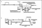
Removing and installing the timing belt (4A-GE (AE92, AW11 and AT160)). 1 - pulley to
crankshaft (alternator drive pulley and coolant pump
sti), 2 - crankshaft pulley mounting bolt (MZ = 137 N.m), 3 - wedge
howling drive belt for the generator and coolant pump, 4 - for
shield cover No. 1 timing belt, 5 - coolant pump pulley,
6 - protective cover No. 2 of the timing belt, 7 - protective cover No. 3 of the timing belt,
8 - protective casing of the engine wiring, 9 - protective gasket
timing belt covers, 10 - timing belt tensioner, 11 - mounting bolt
timing belt tension roller (MZ = 37 N.m) (for AW model on the head
Timing, 13 - tension roller spring, 14 - timing belt
(timing belt), 15 and 16 - toothed camshaft pulleys respectively
inlet and outlet valves, 17 and 18 - mounting bolts
toothed pulleys of camshafts, respectively, inlet and
exhaust valves MZ = 47 Nm (AE92 until 1987, AW11 and AT160).
MZ = 59 Nm (AE92 after 1987). 19 - a gear pulley of a cranked shaft
for timing belt.
Otherwise, check
crankshaft for one revolution (360°).
5. Remove the crankshaft pulley.
a) Using the right tool
loosen the fixing bolt
b) Using a puller, remove
(compress) the crankshaft pulley.
4A-F, 5A-F and 4A-FE (AE92, AE95
AT171 and AT180).
6. Remove belt guards
timing drive.

4A-FE(AE101 AND A T 1 9 0) ,
5A-FE and 7A-FE.
4A-GE
7. Remove the belt guide
timing drive.
8. Remove the timing belt.
Attention: in case of reuse
belt use, draw
belt direction arrow
(in the direction of rotation of the crankshaft
motor shaft) and make marks
on the belt and pulleys, as shown in
drawings.
a) Loosen the tension bolt
foot roller, move it until it stops
ra to the left and then temporarily fix
rut it in this position with the same
mounting bolt.
Removal and installation of the timing belt (4A-GE (AE101, AE111)). 1 - washer tank,
2 - hydraulic booster reservoir, 3 - right engine support, 4 - protective cover
wires of the ignition system, 5 - oil filler cap,
6 - spark plug high voltage wires, 7 - spark plugs, 8 - tooth
Timing belt tensioner, 11 - protective cover No. 1 of the timing belt, 12 - pulley to
crankshaft (alternator drive pulley and coolant pump
sti), 13 - right engine protection cover, 14 - compresso drive belt
air conditioner and power steering pump, 15 - generator drive belt
and coolant pump, 16 - coolant pump pulley,
17 - tensioner roller for the drive belt of the generator and the cooling pump
fluid, 18 - protective cover No. 3 timing belt, 19 - protective cover No. 2
timing belt, 20 - washer pump connectors.
Engine - mechanical part
(4A-GE(AE101,AE111))
a) Unscrew the nuts (bolts) and remove
the timing belt tensioner.
b) Remove the timing belt.
Attention: when the timing belt is removed, do not
turn junction
and crankshafts to avoid
collision between pistons and valves.

Engine - mechanical part
9.(All except 4A-GE (AE101, AE111))
Remove the tension roller and tension
spring by completely unscrewing the bolt
tension roller attachment.
10. If necessary, remove the gear
crankshaft pulley. When
difficulties, use 2 screwdrivers.
Attention: to prevent
damage to cylinder block elements
ditch place a rag as shown
on the image.
11.(All except 4A-GE (AE101, AE111))
If necessary, remove the gear
distributor drive pulley
shaft (4A-F, 5A-F, 4A-FE, 5A-FE and
7A-FE) or drive pulleys
camshafts (4A-GE
(AE92,AW11,AT160)).
Holding the camshaft
from cranking by setting times
water wrench on his hex
part, unscrew the fixing bolt
and remove the pulley.
Note: for 4A-GE (AE92, AW11,
AT160) remove the pulley from each race
limiting shaft.
4A-F, 5A-F, 4A-FE, 5A-FE and 7A-FE.
4A-GE(AE92,AW11,AT160).
3.(All except 4A-GE (AE101, AE111))
Check the tension roller spring.
Measure the free length of the spring
condition (see picture), as well as
Lie required for a given de
formations (stretch marks) of the spring ("mouth
new "amplifying).
Attention: when performing this operation
walkie-talkie do not damage the wrench
what is the head of the block.
(4A-GE(AE101,AE111))
See relevant procedures
section "Checking and adjusting the
valve clearances" (p. 9-15).
Checking the state of the elements
timing gear
1. Check the timing belt
Timing.
Attention:
The belt must not be bent
twist or turn inside
her side out.
The belt must not contact
wash with oil, water or steam.
Can't use tension
belt when loosening or
turning the fixing bolt
camshaft pulley.
If you have the following
defects, check their possible
a) Premature dissection
or broken belt, check
the correctness of the installation of the belt and its
shield covers.
b) Damage or breakage
belt teeth check fastening
camshaft.
c) With significant wear or
damage on the outer surface
belt, check the presence of
damage or dents on the surface
tension roller.
d) If there is wear or damage
only one side of the belt
check the condition of the guide
belt and/or pulleys.
e) If there is significant wear
check the condition of the belt teeth
protective covers, correct
ness of installation of the gasket and cash
any foreign objects on
pulley teeth.
If there are defects
replace the timing belt.
2. Make sure the tension roller
rotates smoothly, without jamming. IN
otherwise, replace the roller.
The length of the spring in the free state
early releases 43.3 mm
late releases 38.4 mm
4A-FE (Models AE92, AE95,
AT171.AT180) 43.3 mm
4A-FE (Models AE101,
AT190) 35.3 mm
5A-FE 36.9mm
7A-FE 31.8mm
4A-GE (models AE92, AW11
and AT160) 43.5 mm
Force required to increase
spring length to "installation"
states:
early releases (50.2 mm) 69H
later releases
(50.2 mm) 35.5 - 39.5 N
4A-FE (Models AE92, AE95,
AT171, AT180) (50.2 mm) 65-73 N
4A-FE (Models AE101,
AT190) (43.6 mm) 35-39H
5A-FE (43.6mm) With 34 -38 N
7A-FE (37.6 mm) 47.5 - 51.5 N
4A-GE (models AE92, AW11
and AT160) (50.2 mm) 93 - 103 N
If the spring length and/or "set
internal" force do not correspond
specifications, replace
4.(4A-GE(AE101,AE111))
Check tensioner seal for
no grease leaks, and the stem is
no wear, cracks or scratches.
Note: minor traces
lubricants on the stem seal are not
indicate a malfunction on
loader.
Timing belt installation
Note: Don't get hit
water or oil on the gear
camshaft pulleys
shafts and keep them in
purity.
1.(All except 4A-GE (AE101, AE111))
Install the drive pulley
camshaft (if
(4A-F, 5A-F, 4A-FE, 5A-FE and 7A-FE)
a) Align the dowel pin
on the toe of the camshaft with
groove of the toothed pulley and fit
those pulley on the camshaft.
Attention: for 4A-FE, 5A-FE and 7A-FE
2 types of pulleys are used with one
or two grooves, in the last
case dowel pin on
camshaft wear
should be aligned with the groove,
labeled accordingly
("A" - 4A-FE, "K" - 5A-FE,"E" - 7A-FE).

Engine - mechanical part
b) Using the gear bolt
that crankshaft pulley,
return the crankshaft and
Keep the sync marks on
toothed pulley and on the oil housing
foot pump.
(4A-GE(AE92, AW11 and AT160))
a) By setting divorce in turn
wrench for hex sections
camshafts, rotate
them and align the synchronizing
marks on the gear pulleys
casting shaft and on the protective
cover #4 of the timing belt.
b) Rotate the crankshaft and
fit sync marks
on the toothed pulley and on the housing
lye pump.
(4A-GE(AE101,AE111))
a) Make sure the labels on the
head cover and pulleys.
4A-F and 5A-F.
5. Install the piston of the 1st cylinder in
TDC position at the end of the compression stroke.
(4A-F, 5A-F, 4A-FE, 5A-FE and 7A-FE)
a) Installing the wrench on
hex section
shaft, rotate it and
fit the mark on the bearing cover
nick camshaft with
the center of the small hole on the pulley
camshaft (4A-F and
5A-F) or with hole center,
labeled accordingly
("A" - 4A-FE, "K" - 5A-FE, "E" - 7A-FE).
c) Holding each - distribute
body shaft for its hexagonal
part with an adjustable wrench, tighten
distribution pulley bolt
body shaft (MZ = 59 Nm).
2.(4A-GE)
Install qi head covers
lindrow (see "Installing the block head
ka cylinders").
b) Temporarily install the crepe bolt
pulley.
c) Holding the distributive
shaft for its hex part times
with a water wrench, tighten the bolt
capturing the camshaft pulley.
Torque:
4A-F, 5A-F 47 Nm
4A-FE. 5A-FE and 7A-FE 59 N.m
(4A-GE (AE92, AW11 and AT160))
a) Position the installation
camshaft pins,
as it shown on the picture.
b) Align the dowel pins
camshafts with grooves
kami toothed pulleys and fit"
pulleys for camshafts.
In this case, the installation marks should
we be located at the top like
shown in the figure.
3. Install the crankshaft pulley
that shaft (if removed).
a) Align the key on the crank
tom shaft with keyway
toothed pulley.
b) Put the pulley on the toe of the crank
of that shaft to the stop by flanging in
inside.
4.(All except 4A-GE (AE101, AE111))
Temporarily install the tension roller
and tension spring.
a) Fix the roller with the bolt without tightening
bending the last one.
b) Install the tension spring.
c) Pull the roller to the left as far as it will go and
tighten the bolt.
Svyatoslav, Kyiv ( [email protected])
The phenomenon and repair of "diesel" noise on old (mileage 250-300 thousand km) 4A-FE engines.
"Diesel" noise occurs most often in throttle mode or engine braking mode. It is clearly audible from the passenger compartment at a speed of 1500-2500 rpm, as well as with the hood open when the gas is released. Initially, it may seem that this noise in frequency and sound resembles the sound of unadjusted valve clearances, or a dangling camshaft. Because of this, those who want to eliminate it often start repairs from the cylinder head (adjusting valve clearances, lowering the yokes, checking whether the gear on the driven camshaft is cocked). Another suggested repair option is an oil change.
I tried all these options, but the noise remained unchanged, as a result of which I decided to replace the piston. Even when changing the oil at 290000, I filled in the Hado 10W40 semi-synthetic oil. And he managed to push 2 repair tubes, but the miracle did not happen. The last of the possible reasons remained - play in the finger-piston pair.
The mileage of my car (Toyota Carina E XL station wagon, 95 onwards; English assembly) was 290,200 km at the time of repair (according to the odometer), moreover, I can assume that on a station wagon with air conditioning, the 1.6 liter engine was somewhat overloaded in terms of compared to a conventional sedan or hatchback. That is, the time has come!
To replace the piston, you need the following:
- Faith in the best and hope for success!!!
- Tools and fixtures:
1. Socket wrench (head) for 10 (for a square of 1/2 and 1/4 inches), 12, 14, 15, 17.
2. Socket wrench (head) (sprocket for 12 rays) for 10 and 14 (for a 1/2 inch square (necessarily no smaller square!) And from high-quality steel !!!). (Required for cylinder head bolts and connecting rod bearing nuts).
3. A socket wrench (ratchet) for 1/2 and 1/4 inches.
4. Torque wrench (up to 35 N*m) (for tightening critical connections).
5. Socket wrench extension (100-150 mm)
6. Wrench for 10 (for unscrewing hard-to-reach fasteners).
7. Adjustable wrench for turning the camshafts.
8. Pliers (remove spring clamps from hoses)
9. Small metalwork vise (jaw size 50x15). (I clamped the head in them by 10 and unscrewed the long stud screws securing the valve cover, and also with their help pressed out and pressed the fingers into the pistons (see photo with a press)).
10. Press up to 3 tons (for repressing fingers and clamping the head by 10 in a vice)
11. To remove the pallet, several flat screwdrivers or knives.
12. Phillips screwdriver with a hexagonal tip (for unscrewing the bolts of the RV yokes near the candle wells).
13. Scraper plate (for cleaning the surfaces of the cylinder head, BC and pan from the remnants of sealant and gaskets).
14. Measuring tool: micrometer 70-90 mm (for measuring the diameter of pistons), bore gauge set to 81 mm (for measuring the geometry of cylinders), vernier caliper (for determining the position of the finger in the piston during pressing), a set of feelers (for controlling valve clearance and gaps in the locks of the rings with the pistons removed). You can also take a micrometer and a 20 mm bore gauge (for measuring the diameter and wear of the fingers).
15. Digital camera - for a report and additional information during assembly! ;O))
16. A book with the dimensions of the CPG and the moments and methods for disassembling and assembling the engine.
17. Hat (so that the oil does not drip onto the hair when the pan is removed). Even if the pan has been removed for a long time, then a drop of oil that was going to drip all night will drip exactly when you are under the engine! Repeatedly checked by a bald spot !!!
- Materials:
1. Carburetor cleaner (large spray) - 1 pc.
2. Silicone sealant (oil-resistant) - 1 tube.
3. VD-40 (or other flavored kerosene for loosening the exhaust pipe bolts).
4. Litol-24 (for tightening the ski mounting bolts)
5. Cotton rags in unlimited quantities.
6. Several cardboard boxes for folding fasteners and camshaft yokes (PB).
7. Tanks for draining antifreeze and oil (5 liters each).
8. Tray (with dimensions 500x400) (substitute under the engine when removing the cylinder head).
9. Engine oil (according to the engine manual) in the required quantity.
10. Antifreeze in the required quantity.
- Parts:
1. A set of pistons (they usually offer a standard size of 80.93 mm), but just in case (not knowing the past of the car) I also took (with a return condition) a repair size that is 0.5 mm larger. - $75 (one set).
2. A set of rings (I also took the original in 2 sizes) - $ 65 (one set).
3. A set of engine gaskets (but you could get by with one gasket under the cylinder head) - $ 55.
4. Gasket exhaust manifold / downpipe - $ 3.
Before disassembling the engine, it is very useful to wash the entire engine compartment at the sink - there is no need for extra dirt!
I decided to disassemble to a minimum, because I was very limited in time. Judging by the set of engine gaskets, it was for a regular, not a lean 4A-FE engine. Therefore, I decided not to remove the intake manifold from the cylinder head (so as not to damage the gasket). And if so, then the exhaust manifold could be left on the cylinder head, undocking it from the exhaust pipe.
I will briefly describe the disassembly sequence:
At this point, in all instructions, the negative terminal of the battery is removed, but I deliberately decided not to remove it so as not to reset the computer's memory (for the purity of the experiment) ... and to listen to the radio during the repair; o)
1. Plentifully filled with VD-40 rusty bolts of the exhaust pipe.
2. I drained the oil and antifreeze by unscrewing the bottom plugs and caps on the filler necks.
3. I undocked the hoses of the vacuum systems, wires of temperature sensors, fan, throttle position, wires of the cold start system, lambda probe, high-voltage, spark plug wires, wires of HBO injectors and gas and gasoline supply hoses. In general, everything that fits the intake and exhaust manifold.
2. Removed the first yoke of the inlet RV and screwed in a temporary bolt through the spring-loaded gear.
3. Consistently loosened the bolts of the rest of the RV yokes (to unscrew the bolts - studs on which the valve cover is attached, I had to use a 10 head clamped in a vise (using a press)). The bolts located near the candle wells were unscrewed with a small 10 head with a Phillips screwdriver inserted into it (with a hexagonal sting and a spanner wrench worn on this hexagon).
4. Removed the inlet RV and checked whether the head fits 10 (asterisk) to the cylinder head bolts. Luckily, it fit perfectly. In addition to the sprocket itself, the outer diameter of the head is also important. It should not be more than 22.5 mm, otherwise it will not fit!
5. He removed the exhaust RV, first unscrewing the timing belt gear bolt and removing it (head by 14), then, sequentially loosening first the outer bolts of the yokes, then the central ones, removed the RV itself.
6. Removed the distributor by unscrewing the bolts of the distributor yoke and adjusting (head 12). Before removing the distributor, it is advisable to mark its position relative to the cylinder head.
7. Removed the bolts of the power steering bracket (head 12),
8. Timing belt cover (4 M6 bolts).
9. He removed the oil dipstick tube (M6 bolt) and took it out, also unscrewed the cooling pump pipe (head 12) (the oil dipstick tube is attached just to this flange).
3. Since access to the pallet was limited due to an incomprehensible aluminum trough connecting the gearbox to the cylinder block, I decided to remove it. I unscrewed 4 bolts, but the trough could not be removed because of the ski.
4. I thought about unscrewing the ski under the engine, but I could not unscrew the 2 front ski nuts. I think that before me this car was broken and instead of the studs with nuts there were bolts with M10 self-locking nuts. When trying to unscrew, the bolts turned, and I decided to leave them in place, unscrewing only the back of the ski. As a result, I unscrewed the main bolt of the front engine mount and 3 rear ski bolts.
5. As soon as I unscrewed the 3rd rear bolt of the ski, it bent back, and the aluminum trough fell out with a twist ... in my face. It hurt... :o/.
6. Next, I unscrewed the M6 bolts and nuts securing the engine pan. And he tried to pull it off - and the pipes! I had to take all possible flat screwdrivers, knives, probes to tear off the pallet. As a result, having unbent the front sides of the pallet, I removed it.
Also, I did not notice some kind of brown connector of a system unknown to me, located somewhere above the starter, but it successfully undocked itself when removing the cylinder head.
Otherwise, the removal of the cylinder head was successful. I pulled it out myself. The weight in it is no more than 25 kg, but you have to be very careful not to demolish the protruding ones - the fan sensor and the lambda probe. It is advisable to number the adjusting washers (with an ordinary marker, after wiping them with a rag with a carb cleaner) - this is in case the washers fall out. He put the removed cylinder head on a clean cardboard - away from sand and dust.
Piston:
The piston was removed and installed alternately. To unscrew the connecting rod nuts, a 14-star head is required. The unscrewed connecting rod with the piston moves up with your fingers until it falls out of the cylinder block. In this case, it is very important not to confuse the drop-down connecting rod bearings !!!
I examined the dismantled assembly and measured it as much as possible. Piston changed before me. Moreover, their diameter in the control zone (25 mm from the top) was exactly the same as on the new pistons. The radial play in the piston-finger connection was not felt by the hand, but this is due to the oil. Axial movement along the finger is free. Judging by the soot on the upper part (up to the rings), some pistons were displaced along the axes of the fingers and rubbed against the cylinders by the surface (perpendicular to the axis of the fingers). Having measured the position of the fingers with a rod relative to the cylindrical part of the piston, he determined that some fingers were displaced along the axis up to 1 mm.
Further, when pressing new fingers, I controlled the position of the fingers in the piston (I chose the axial clearance in one direction and measured the distance from the end of the finger to the piston wall, then in the other direction). (I had to drive my fingers back and forth, but in the end I achieved an error of 0.5 mm). For this reason, I believe that landing a cold finger into a hot crank is only possible under ideal conditions, with a controlled finger stop. In my conditions it was impossible and I did not bother with landing "hot". I pressed it in, lubricating the hole in the piston and connecting rod with engine oil. Fortunately, on the fingers, the butt was filled with a smooth radius and did not shake either the connecting rod or the piston.
The old pins had noticeable wear in the piston boss areas (0.03 mm in relation to the central part of the pin). It was not possible to accurately measure the output on the piston bosses, but there was no particular ellipse there. All rings were movable in the piston grooves, and the oil channels (holes in the oil scraper ring area) were free of carbon deposits and dirt.
Before pressing in new pistons, I measured the geometry of the central and upper parts of the cylinders, as well as the new pistons. The goal is to fit larger pistons into more worn out cylinders. But the new pistons were almost identical in diameter. By weight, I did not control them.
Another important point when pressing in is the correct position of the connecting rod relative to the piston. There is an influx on the connecting rod (above the crankshaft liner) - this is a special marker indicating the location of the connecting rod to the front of the crankshaft (alternator pulley), (there is the same influx on the lower beds of the connecting rod liners). On the piston - at the top - two deep cores - also to the front of the crankshaft.
I also checked the gaps in the locks of the rings. To do this, the compression ring (first old, then new) is inserted into the cylinder and lowered by the piston to a depth of 87 mm. The gap in the ring is measured with a feeler gauge. On the old ones there was a gap of 0.3 mm, on the new rings 0.25 mm, which indicates that I changed the rings in vain! The allowable gap, let me remind you, is 1.05 mm for ring No. 1. The following should be noted here: If I had guessed to mark the positions of the locks of the old rings relative to the pistons (when pulling out the old pistons), then the old rings could be safely put on the new pistons in the same position. Thus, it would be possible to save $65. And engine break-in time!
Next, piston rings must be installed on the pistons. Installed without adaptation - with fingers. First - the oil scraper ring separator, then the lower scraper of the oil scraper ring, then the upper one. Then the 2nd and 1st compression rings. The location of the locks of the rings - necessarily according to the book !!!
With the pallet removed, it is still necessary to check the axial play of the crankshaft (I did not do this), it seemed visually that the play is very small ... (and permissible up to 0.3 mm). When removing - installing connecting rod assemblies, the crankshaft rotates manually by the generator pulley.
Assembly:
Before installing pistons with connecting rods, cylinders, piston pins and rings, connecting rod bearings, lubricate with fresh engine oil. When installing the lower beds of the connecting rods, it is necessary to check the position of the liners. They must stand in place (without displacement, otherwise jamming is possible). After installing all the connecting rods (tightening with a torque of 29 Nm, in several approaches), it is necessary to check the ease of rotation of the crankshaft. It should rotate by hand on the alternator pulley. Otherwise, it is necessary to look for and eliminate the skew in the liners.
Pallet and ski installation:
Cleaned of old sealant, the sump flange, like the surface on the cylinder block, is carefully degreased with a carb cleaner. Then a layer of sealant is applied to the pallet (see instructions) and the pallet is set aside for several minutes. Meanwhile, the oil receiver is installed. And behind it is a tray. First, 2 nuts are baited in the middle - then everything else and tightened by hand. Later (after 15-20 minutes) - with a key (head at 10).
You can immediately put the hose from the oil cooler on the pallet and install the ski and the bolt of the front engine mount (it is advisable to lubricate the bolts with Litol - to slow down the rusting of the threaded connection).
Cylinder head installation:
Before installing the cylinder head, it is necessary to carefully clean the planes of the cylinder head and BC with a scraper plate, as well as the mounting flange of the pump pipe (near the pump from the back of the cylinder head (the one where the oil dipstick is attached)). It is advisable to remove oil and antifreeze puddles from the threaded holes so as not to split when tightening the BC with bolts.
Put a new gasket under the cylinder head (I smeared it a little with silicone in areas close to the edges - according to the old memory of repeated repairs of the Moscow 412 engine). I smeared the pump nozzle with silicone (the one with the oil dipstick). Next, the cylinder head can be set! Here it is necessary to note one feature! All cylinder head bolts on the intake manifold mounting side are shorter than on the exhaust side !!! I tighten the installed head with bolts by hand (using a 10 sprocket head with an extension). Then I screw on the pump nozzle. When all the cylinder head bolts are baited, I start tightening (the sequence and method are as in the book), and then another control tightening of 80 Nm (this is just in case).
After installing the cylinder head, the P-shafts are being installed. The contact planes of the yokes with the cylinder head are thoroughly cleaned of debris, and the threaded mounting holes are cleaned of oil. It is very important to put the yokes in their places (for this they are marked at the factory).
I determined the position of the crankshaft by the "0" mark on the timing belt cover and the notch on the alternator pulley. The position of the outlet RV is on the pin in the flange of the belt gear. If it is at the top, then the PB is in the TDC position of the 1st cylinder. Next, I put the RV oil seal in the place cleaned by the carb cleaner. I put the belt gear together with the belt and tightened it with a fixing bolt (14 head). Unfortunately, the timing belt could not be put in the old place (previously marked with a marker), but it was desirable to do so. Next, I installed the distributor, after removing the old sealant and oil with a carb cleaner, and applying a new sealant. The position of the distributor was set according to a pre-applied mark. By the way, as for the distributor, the photo shows burnt electrodes. This may be the cause of uneven operation, tripling, "weakness" of the engine, and the result is increased fuel consumption and a desire to change everything in the world (candles, explosive wires, lambda probe, car, etc.). It is eliminated in an elementary way - gently scraped off with a screwdriver. Similarly - on the opposite contact of the slider. I recommend cleaning every 20-30 t.km.
Next, the inlet RV is installed, be sure to align the necessary (!) Marks on the gears of the shafts. First, the central yokes of the inlet RV are installed, then, having removed the temporary bolt from the gear, the first yoke is placed. All fastening bolts are tightened to the required torque in the appropriate sequence (according to the book). Next, a plastic timing belt cover is installed (4 M6 bolts) and only then, carefully wiping the valve cover and cylinder head contact area with a rag with a carb cleaner and applying a new sealant - the valve cover itself. Here, in fact, are all the tricks. It remains to hang all the tubes, wires, tighten the power steering and generator belts, fill in antifreeze (before filling, I recommend wiping the neck of the radiator, creating a vacuum on it with your mouth (so to check the tightness)); fill with oil (do not forget to tighten the drain plugs!). Install an aluminum trough, a ski (lubricating the bolts with salidol) and a front pipe with gaskets.
The launch was not instant - it was necessary to pump empty fuel tanks. The garage was filled with thick oily smoke - this is from piston lubrication. Further - the smoke becomes more burnt in smell - this is oil and dirt burning out from the exhaust manifold and the exhaust pipe ... Further (if everything worked out) - we enjoy the absence of "diesel" noise !!! I think it will be useful when driving to observe a gentle mode - for engine break-in (at least 1000 km).
The timing belt is one of the important parts in an automotive device. It is responsible for synchronizing the rotations of the camshaft and crankshaft.
The timing belt is one of the important parts in an automotive device. It is responsible for synchronizing the rotations of the camshaft and crankshaft. Due to constant friction on the pulleys, the part wears out over time and becomes unusable. In particularly problematic situations, the belt may even break, after which the car will not be able to move further. To avoid such a situation, it is necessary to monitor the condition of the belt and change it in time.
There are several of the most common reasons why the timing belt may break. These are the following factors:
- the motor resource, which is provided by the manufacturer, has been exhausted;
- manufacturing defect;
- hit on the spare part of oil and dirt;
- foreign objects getting on the belt;
- jamming of one of the shafts, distribution or crankshaft;
- pump jamming;
- tension roller failure.
In a word, every car owner needs to monitor the condition of the timing belt, paying attention to suspicious signs. Otherwise, a gap may occur, which can lead to serious negative consequences.

Most often, a broken timing belt does not lead to serious consequences. The main problem is the complete stop of the vehicle, on which it will no longer be possible to move. It is not possible to fix the breakdown on the spot, because the car must be driven into a pit or a lift. Therefore, the driver will have to take care of delivering the car to the nearest car service or other place where repairs can be carried out. This will require additional financial and time costs.
Sometimes a broken belt can lead to more serious consequences. So, bent valves can be the result. They will have to be replaced with new ones.
If the part ruptured at idle, then many valves are unlikely to be damaged. If the break occurs when the gear is engaged, then there is a risk that all valves will be bent. In fact, it doesn’t matter how many parts were damaged. Experienced mechanics recommend changing the entire kit at once.
Even more serious is the situation when not only the valves are bent, but the bushings are also destroyed. In this case, the pistons can be pierced by fragments. The result will be the repair of the internal combustion engine, for which you will have to pay a lot of money.
To avoid the negative situations described above, it is necessary to monitor the condition of the belt and replace it with a new one in time. Timely replacement will give the motorist confidence that the break will not occur at the most unexpected moment.

Most often, the timing belt is changed upon reaching a certain mileage. On Toyota cars, this figure is 100 thousand kilometers. If the car has already passed so much, then it is necessary to make a replacement. Otherwise, there is a risk that the belt will soon break due to the exhausted motor resource.
It is also necessary to change the part if damage is visible visually. They can sometimes be detected during the passage of maintenance or when eliminating other malfunctions.
If it is clear that the belt is really worn out, then a new spare part should be installed without waiting for the specified mileage to be reached.
Traces of oil under the car may indicate the need for replacement. In case of leaks, liquid can get on the belt, due to which its material loses its properties. As a result, the part can no longer perform its functions.
Another possible sign of problems with the belt element is rustling sounds coming from under the hood. If such signs are present, then a diagnosis should be made and the belt inspected.

There is a certain sequence of actions that must be followed in order to correctly replace the 4A-GE motor. First you need to get to it and remove it.
Before installing a new part, it is important to align timing marks 4A- G.E.. Without this, the process will not complete normally.
So, to remove the belt, you must:
- Open the hood.
- Disconnect battery terminals. This is done in order to avoid accidental starting of the engine. This may be due to sensors being triggered.
- Remove washer reservoir.
- Remove the tank into which the power steering fluid is poured.
- Remove the right part of the engine crankcase.
- Set the number one piston to top dead center on the compression stroke.
- Remove the power steering pump and A/C compressor belt.
- Loosen the bolts that secure the antifreeze pump pulley.
- Remove the alternator and coolant pump drive belts.
- Remove the alternator belt pulley.
- Remove the crankshaft pulley by first unscrewing the bolt.
- Remove the right engine support.
- Remove timing belt covers.
- Remove the timing belt tensioner.
- Dismantle the belt element itself.
With the belt removed, the camshaft and crankshaft must not be turned under any circumstances. Otherwise, it may lead to bending of the valves.
If necessary, remove the crankshaft sprocket. This is usually done in order to change worn seals. If these elements do not require replacement, then you can do without removing the pulley.

During the replacement process, the condition of other spare parts should be assessed in parallel so that they can be replaced immediately if necessary. In particular, the camshaft and crankshaft oil seals require special attention. If there are leaks, then these parts must be changed. If they do not leak, then you can do nothing. But if the oil seals have been used for a long time, then it is worth putting new ones together with the belt. Otherwise, after a short time there is a risk of those same leaks.
Attachment belts should also be considered. If they do not look the best, they are worn out, then new ones must be installed. It is also worth checking the tension and bypass rollers of the timing belt. They should not make extraneous noise. If the rollers whistle and creak, then it's time to change them too so that the engine runs normally and there are no new breakdowns.

Many car owners are concerned about the question of which belt to use. Is it worth giving preference to the original part, or can you save money by purchasing an analogue?
As for analogues, it is not known how they will behave. Sometimes installing them can do a lot of damage due to a mismatch. Therefore, the optimal solution is the choice of the original. In addition, the belt is not the most expensive spare part, it is definitely not worth saving on buying it.
In a word, the timing belt is a special part that must be changed on time and not allowed to wear out. Otherwise, it can break, and this can happen at the most unexpected moment. Breakage of a belt spare part can lead to serious negative consequences. Therefore, it must be changed according to mileage or in case of physical damage. At the same time, you need to pay attention to other spare parts.
Dismantling (for 4A-FE engine)
· Disconnect the negative terminal from the battery.
· Pump out liquid from the windshield washer reservoir on the right in the engine compartment, then unscrew the fixing screws, disconnect the tube and wiring, and remove the reservoir.
· Remove the camshaft cover.
· Loosen the bolts holding the drive pulley to the water pump one or two turns (this is easier to do when the belt is not removed);
Note: The pulley will later need to be moved to the side to remove the middle camshaft belt cover.
· Place wedges under the rear wheels, jack up the front of the vehicle and support it on jack stands.
· Remove the right front wheel, then remove the bolts and mudguard from under the right side of the engine compartment.
· Loosen the water pump pulley bolts.
· Remove the pivot bolt and the alternator retaining bolt.
· Loosen the alternator set screw and remove the alternator belt.
· Remove the water pump pulley bolts.
· Remove the high voltage wires and turn out the spark plugs.
· Remove the wiring and clips around the cylinder head cover, remove the protective casing 2 of the wiring and remove the ventilation hoses 6, 7 of the crankcase from the cylinder head cover.
Rice. 2.3.1.1.
General view of the 4A-FE engine,
where: 1 - high voltage wires; 2 - protective casing of wiring around the cover of the cylinder head; 3 - fuel pressure regulator; 3 - fuel injector ramp; 5 - inlet pipe; 6, 7 - crankcase ventilation hoses; 8 - nozzle connector (injector); 9 - low-voltage connector of the ignition distributor; 10 - ignition distributor; 11 - upper branch pipe of the radiator of the cooling system.
· Remove nuts, O-rings, cylinder head cover and cylinder head cover seal.
· Set the piston of cylinder No. 1 to T.D.T. the end of the compression stroke by placing the groove on the crankshaft pulley opposite the "O" mark on the lower timing cover. Check if the hole in the camshaft pulley is opposite the mark on the bearing cap. If not, turn the crankshaft another full turn (360°).
· Remove the crankshaft pulley bolt and remove the pulley using puller SST 09213-60017 .
· Remove the three timing covers.
· Remove the belt guide roller.
· Remove the timing belt.
Attention: If the belt is to be used again, mark it with an arrow in the direction of rotation of the engine, as well as marks on the belt drive wheels and on the belt.
· Unscrew the bolt of the outer roller, push the idler roller as far to the left as possible and temporarily fix it.
· Remove the timing belt.
Attention: Do not turn the crankshaft and camshaft any more after removing the belt, because otherwise the valves may touch the pistons.
· Remove the idler pulley bolt, idler pulley and tension spring.
· Slide the belt pulley off the crankshaft. Use, if required, two screwdrivers; while doing this, place cleaning cloths between the engine block and the screwdrivers to avoid damage.
· Remove the camshaft pulley. When loosening the bolts, hold the camshaft with a socket wrench on the hex part.
Inspection (for 4A-FE engine)
· Check the distributor drive belt for wear and cracks.
Attention: Do not bend the belt. If in doubt, replace the belt. Broken or broken teeth indicate a blocked camshaft, oil pump, or water pump.
· Check the tensioner for cracks on the outside of the belt.
· If one-sided wear of the belt is detected, check the belt idler and the alignment of the belt pulleys.
· Check that the idler pulley rotates smoothly and has no play. Replace if necessary.
· Check the free length of the tension spring, it should be 35.3 mm (Fig. 2.3.1.2). Check spring tension at 43.6 mm length. It should be 35-39 N (3.6-4.0 kg). Replace spring if necessary.

Fig.2.3.1.2.
Checking the free length of the spring of the camshaft drive belt tensioner
Installation(for 4A-FE engine)
· Position the dowel pin on the camshaft in line with the groove on the camshaft pulley and slide the pulley onto the shaft.
· Tighten the belt pulley bolt while holding the camshaft with a socket wrench on the hex part.
· Place the V-key in the crankshaft against the keyway of the belt pulley and slide the belt pulley onto the shaft, with the edge that appears facing inwards;
· Install the tension roller with the fixing bolt, but do not tighten it yet.
· Install the spring, move the tension roller as far to the left as possible and tighten the bolt.
· Align the hole in the camshaft pulley against the mark on the bearing cap by turning the camshaft with the socket wrench on the hex part.
· Align the marks on the crankshaft pulley and on the oil pump housing opposite each other by turning the crankshaft.
Install the distributor drive belt (when reusing the belt, pay attention to the marks made during disassembly) and check the belt tension between the camshaft and camshaft pulleys.
· Loosen the idler pulley bolt and slowly turn the crankshaft two full turns to the right.
· Check whether the marks of both belt pulleys lie on the same line. (If not, remove the distributor belt and put it back on).
· Tighten the idler pulley bolt.
· Remove the crankshaft pulley bolt.
· Check the belt deflection between the camshaft and crankshaft pulleys. It should be 5-6 mm at 20 N (2 kg). If not, adjust the tensioner again.
· Fit the belt idler with the hollow end facing out.
· Fit the distributor caps (from bottom to top).
· Install the pulley on the toe of the crankshaft and tighten the pulley bolt.
· Fit the cylinder head cover with a new seal.
· Connect the crankcase vent hoses and spark plug wires.
· Install the protective cap of wiring, wires and spark plugs.
· Install the water pump pulley to the alternator belt.
· Adjust belt tension. The deflection between the water pump and the generator at 98N (10 kg) for a new belt should be 7-9 mm, and for a used belt -11.5-13.5 mm.
· After installing a new alternator belt, let the engine run for 5 minutes. and check the belt tension again.
· Install the mudguard and right wheel and lower the vehicle to the ground.
· Install and fill the windshield washer reservoir, then connect the negative battery cable.
Dismantling (for 3S-FE engine)
· Disconnect the negative battery terminal.
· Remove the alternator as described. Also remove the power steering pump drive belt.
· Remove the spark plugs.
· Set the piston in cylinder No. 1 to TDC.
· Place wedges under the rear wheels, jack up the front of the vehicle and support it on jack stands. Remove the right wheel, then remove the bolts, and remove the mudguard from under the right side of the engine compartment.
· Secure the crankshaft against rotation in order to loosen the pulley mounting bolt.
Note: Service station mechanics use a special tool for this purpose, which is screwed to the pulley. You can make a similar device yourself. Alternatively, on a manual gearbox, you can select 4th gear and, in addition, press the brake pedal. On an automatic transmission, remove the booster cover from the bottom of the transmission and insert a wide screwdriver through the opening into the teeth of the starter ring.
· Loosen the crankshaft pulley bolt and remove the pulley from the crankshaft nose. If the fit is tight, use a suitable puller.
· Loosen the bolts and remove the upper and lower covers of the camshaft drive mechanism and, where present, remove the gaskets.
· Remove the outer toothed belt guide from the crankshaft.

Fig.2.3.2.1.
Removing the outer camshaft belt guide from the crankshaft nose
· If the same belt is to be used again in the future, mark the direction of rotation with an arrow. Also mark its position relative to the crankshaft and camshaft sprockets.
· Loosen the bolt securing the camshaft drive belt tensioner to the cylinder block. Using a screwdriver, push the tensioner through the protective pad to loosen the belt, then tighten the bolt to lock the tensioner in this position.
· Remove the toothed belt from the crankshaft and camshaft sprockets, from the oil and water pump drives. To remove the belt, it is necessary to unload and dismantle the right support of the power unit. Before dismantling the support, support the engine with a jack on a pallet through a block of wood.
· With the timing belt removed, DO NOT change the position of the crankshaft or camshaft.
Inspection (for 3S-FE engine)
· Carefully inspect the belt for damage or signs of decomposition. Especially carefully inspect the cavity of the teeth for the detection of incipient cracks.
· In addition to the scheduled replacement according to the maintenance schedule, the camshaft drive belt should be replaced, regardless of age or mileage, if it has any defects or if it has been in contact with water, oil or steam.
· Check that the idler pulley rotates easily without binding.
· Check the free length of the tensioner spring and if it is out of specification (46.0 mm), replace it.
Installation(for 3S-FE engine)
· Before installing the camshaft drive belt, check that the alignment marks on the camshaft sprocket(s) match the marks on the inner cover of the timing drive mechanism, and that the TDC marks on the crankshaft sprocket and on the oil pump housing match. To be more convincing, temporarily install the lower timing belt cover and crankshaft pulley and see if the notch on the pulley aligns with the Oo mark on the cover. After checking, remove the pulley and cover again.
· Fit the toothed belt onto the sprockets and idlers, being careful not to change the position of the sprockets and that the belt is aligned with the ends of the sprockets. If a previously used belt is being installed, make sure that the arrow marked on the belt when removing it is pointing in the right direction and that the marks on the belt and sprocket match. Reinstall the right power block support and tighten the bolts.
· Loosen the tensioner bolt and allow it to move the tensioning pulley against the belt under the action of the spring. Do not tighten the bolt yet. To install the tension mechanism, follow these steps:
(a) Install the outer toothed belt guide with the concave side out, then install the lower camshaft cover with a new gasket (where present) and tighten the bolts.
b) Install the crankshaft pulley and tighten the bolt to the correct torque.
c) Turn the crankshaft clockwise for almost two full turns, then slowly tighten it until the TDC marks match. If the marks do not match, do not rotate the crankshaft counterclockwise, remove the toothed belt and perform the installation procedure again.
d) Turn the crankshaft clockwise one full turn and continue to turn it until the alignment mark matches the mark 450 before TDC on the bottom cover of the camshaft drive mechanism.
e) Tighten the tensioner bolt to the required (24 Nm) torque (24 Nm).