Engines 5А,4А,7А-FE
The most common and today the most widely repaired of Japanese engines is the engines of the (4,5,7) A-FE series. Even a novice mechanic, diagnostician knows about the possible problems of engines of this series. I will try to highlight (collect into a single whole) the problems of these engines. There are few of them, but they cause a lot of trouble to their owners.
Date from scanner:

On the scanner, you can see a short but capacious date, consisting of 16 parameters, by which you can really evaluate the operation of the main engine sensors.
Sensors
Oxygen sensor -

Many owners turn to diagnostics due to increased fuel consumption. One of the reasons is a banal break in the heater in the oxygen sensor. The error is fixed by the control unit code number 21. The heater can be checked with a conventional tester on the sensor contacts (R- 14 Ohm)


Fuel consumption increases due to the lack of correction during warm-up. You will not be able to restore the heater - only a replacement will help. The cost of a new sensor is high, and it makes no sense to install a used one (their operating time is large, so this is a lottery). In such a situation, less reliable universal NTK sensors can be installed as an alternative. The term of their work is short, and the quality leaves much to be desired, so such a replacement is a temporary measure, and it should be done with caution.


When the sensor sensitivity decreases, fuel consumption increases (by 1-3 liters). The operability of the sensor is checked by an oscilloscope on the diagnostic connector block, or directly on the sensor chip (number of switching).

Temperature sensor.
If the sensor does not work correctly, the owner will have a lot of problems. If the measuring element of the sensor breaks, the control unit replaces the sensor readings and fixes its value by 80 degrees and fixes error 22. The engine, with such a malfunction, will operate normally, but only while the engine is warm. As soon as the engine cools down, it will be problematic to start it without doping, due to the short opening time of the injectors. There are frequent cases when the resistance of the sensor changes randomly when the engine is running at H.X. - the revolutions will float


This defect is easy to fix on the scanner, observing the temperature reading. On a warm engine, it should be stable and not randomly change values from 20 to 100 degrees

With such a defect in the sensor, a “black exhaust” is possible, unstable operation on H.X. and, as a result, increased consumption, as well as the inability to start "hot". Only after 10 minutes of sludge. If there is no complete confidence in the correct operation of the sensor, its readings can be replaced by including a 1 kΩ variable resistor or a constant 300 ohm resistor in its circuit for further verification. By changing the readings of the sensor, the change in speed at different temperatures is easily controlled.
Throttle position sensor


A lot of cars go through the process of assembly and disassembly. These are the so-called "constructors". When removing the engine in the field and subsequent assembly, the sensors suffer, on which the engine is often leaned. When the TPS sensor breaks, the engine stops throttling normally. The engine bogs down when revving. The machine switches incorrectly. Error 41 is fixed by the control unit. When replacing a new sensor, it must be adjusted so that the control unit correctly sees the sign of X.X., with the gas pedal fully released (throttle closed). In the absence of a sign of idling, adequate regulation of H.X. will not be carried out. and there will be no forced idling mode during engine braking, which again will entail increased fuel consumption. On engines 4A, 7A, the sensor does not require adjustment, it is installed without the possibility of rotation.
THROTTLE POSITION……0%
IDLE SIGNAL……………….ON
MAP absolute pressure sensor


This sensor is the most reliable of all installed on Japanese cars. His resilience is simply amazing. But it also has a lot of problems, mainly due to improper assembly. Either the receiving “nipple” is broken, and then any passage of air is sealed with glue, or the tightness of the supply tube is violated.


With such a gap, fuel consumption increases, the level of CO in the exhaust increases sharply up to 3%. It is very easy to observe the operation of the sensor on the scanner. The line INTAKE MANIFOLD shows the vacuum in the intake manifold, which is measured by the MAP sensor. When the wiring is broken, the ECU registers error 31. At the same time, the opening time of the injectors sharply increases to 3.5-5ms. and stop the engine.
Knock sensor


The sensor is installed to register detonation knocks (explosions) and indirectly serves as a "corrector" of the ignition timing. The recording element of the sensor is a piezoelectric plate. In the event of a sensor malfunction, or a break in the wiring, at over 3.5-4 tons of revs, the ECU fixes error 52. Sluggishness is observed during acceleration. You can check the performance with an oscilloscope, or by measuring the resistance between the sensor output and the housing (if there is resistance, the sensor needs to be replaced).

crankshaft sensor
On 7A series engines, a crankshaft sensor is installed. A conventional inductive sensor is similar to the ABC sensor and is practically trouble-free in operation. But there are also confusions. With an interturn circuit inside the winding, the generation of pulses at a certain speed is disrupted. This manifests itself as a limitation of engine speed in the range of 3.5-4 tons of revolutions. A kind of cut-off, only at low speeds. It is quite difficult to detect an interturn circuit. The oscilloscope does not show a decrease in the amplitude of the pulses or a change in frequency (during acceleration), and it is quite difficult for a tester to notice changes in Ohm's shares. If you experience symptoms of speed limit at 3-4 thousand, simply replace the sensor with a known good one. In addition, a lot of trouble causes damage to the master ring, which is damaged by negligent mechanics while replacing the front crankshaft oil seal or timing belt. Having broken the teeth of the crown, and restored them by welding, they achieve only a visible absence of damage. At the same time, the crankshaft position sensor ceases to adequately read information, the ignition timing begins to change randomly, which leads to loss of power, unstable engine operation and increased fuel consumption


Injectors (nozzles)


During many years of operation, the nozzles and needles of the injectors are covered with tar and gasoline dust. All this naturally interferes with the correct spray and reduces the performance of the nozzle. With severe pollution, a noticeable shaking of the engine is observed, fuel consumption increases. It is realistic to determine clogging by conducting a gas analysis; according to the readings of oxygen in the exhaust, one can judge the correctness of filling. A reading above one percent will indicate the need to flush the injectors (with the correct timing and normal fuel pressure). Or by installing the injectors on the stand, and checking the performance in the tests. Nozzles are easily cleaned by Lavr, Vince, both on CIP machines and in ultrasound.

Idle valve, IACV


The valve is responsible for engine speed in all modes (warm-up, idling, load). During operation, the valve petal becomes dirty and the stem is wedged. Turnovers hang on warming up or on X.X. (due to the wedge). Tests for changes in speed in scanners during diagnostics for this motor are not provided. The performance of the valve can be assessed by changing the readings of the temperature sensor. Enter the engine in the "cold" mode. Or, having removed the winding from the valve, twist the valve magnet with your hands. Jamming and wedge will be felt immediately. If it is impossible to easily dismantle the valve winding (for example, on the GE series), you can check its operability by connecting to one of the control outputs and measuring the duty cycle of the pulses while simultaneously controlling the RPM. and changing the load on the engine. On a fully warmed-up engine, the duty cycle is approximately 40%, by changing the load (including electrical consumers), an adequate increase in speed in response to a change in duty cycle can be estimated. When the valve is mechanically jammed, a smooth increase in the duty cycle occurs, which does not entail a change in the speed of H.X. You can restore work by cleaning soot and dirt with a carburetor cleaner with the winding removed.


Further adjustment of the valve is to set the speed X.X. On a fully warmed up engine, by rotating the winding on the mounting bolts, they achieve tabular revolutions for this type of car (according to the tag on the hood). Having previously installed the jumper E1-TE1 in the diagnostic block. On the “younger” 4A, 7A engines, the valve has been changed. Instead of the usual two windings, a microcircuit was installed in the body of the valve winding. We changed the valve power supply and the color of the winding plastic (black). It is already pointless to measure the resistance of the windings at the terminals. The valve is supplied with power and a control signal of a rectangular shape with a variable duty cycle.


To make it impossible to remove the winding, non-standard fasteners were installed. But the wedge problem remained. Now, if you clean it with an ordinary cleaner, the grease is washed out of the bearings (the further result is predictable, the same wedge, but already because of the bearing). It is necessary to completely dismantle the valve from the throttle body and then carefully flush the stem with the petal.
Ignition system. Candles.

A very large percentage of cars come to the service with problems in the ignition system. When operating on low-quality gasoline, spark plugs are the first to suffer. They are covered with a red coating (ferrosis). There will be no high-quality sparking with such candles. The engine will work intermittently, with gaps, fuel consumption increases, the level of CO in the exhaust rises. Sandblasting is not able to clean such candles. Only chemistry (silit for a couple of hours) or replacement will help. Another problem is the increase in clearance (simple wear). Drying of the rubber lugs of high-voltage wires, water that got in when washing the motor, which all provoke the formation of a conductive path on the rubber lugs.


Because of them, sparking will not be inside the cylinder, but outside it.
With smooth throttling, the engine runs stably, and with a sharp one, it “crushes”.


In this situation, it is necessary to replace both the candles and the wires at the same time. But sometimes (in the field), if replacement is impossible, you can solve the problem with an ordinary knife and a piece of emery stone (fine fraction). With a knife we cut off the conductive path in the wire, and with a stone we remove the strip from the ceramics of the candle. It should be noted that it is impossible to remove the rubber band from the wire, this will lead to the complete inoperability of the cylinder.

Another problem is related to the incorrect procedure for replacing candles. The wires are pulled out of the wells with force, tearing off the metal tip of the rein.


With such a wire, misfires and floating revolutions are observed. When diagnosing the ignition system, you should always check the performance of the ignition coil on the high-voltage arrester. The simplest test is to look at the spark gap on the spark gap with the engine running.

If the spark disappears or becomes filiform, this indicates an inter-turn short circuit in the coil or a problem in the high voltage wires. A wire break is checked with a resistance tester. Small wire 2-3k, then to increase the long 10-12k.


The closed coil resistance can also be checked with a tester. The resistance of the secondary winding of the broken coil will be less than 12 kΩ.
The next generation coils do not suffer from such ailments (4A.7A), their failure is minimal. Proper cooling and wire thickness eliminated this problem.
Another problem is the current oil seal in the distributor. Oil, falling on the sensors, corrodes the insulation. And when exposed to high voltage, the slider is oxidized (covered with a green coating). The coal turns sour. All this leads to disruption of sparking. In motion, chaotic shootings are observed (into the intake manifold, into the muffler) and crushing.


«
Subtle malfunctions
On modern 4A, 7A engines, the Japanese have changed the firmware of the control unit (apparently for faster engine warm-up). The change is that the engine reaches idle speed only at 85 degrees. The design of the engine cooling system was also changed. Now a small cooling circle intensively passes through the head of the block (not through the pipe behind the engine, as it was before). Of course, the cooling of the head has become more efficient, and the engine as a whole has become more efficient. But in winter, with such cooling during movement, the temperature of the engine reaches a temperature of 75-80 degrees. And as a result, constant warm-up revolutions (1100-1300), increased fuel consumption and nervousness of the owners. You can deal with this problem either by insulating the engine more strongly, or by changing the resistance of the temperature sensor (by deceiving the computer).
Oil
Owners pour oil into the engine indiscriminately, without thinking about the consequences. Few people understand that different types of oils are not compatible and, when mixed, form an insoluble porridge (coke), which leads to the complete destruction of the engine.


All this plasticine cannot be washed off with chemistry, it is cleaned only mechanically. It should be understood that if it is not known what type of old oil, then flushing should be used before changing. And more advice to the owners. Pay attention to the color of the oil dipstick handle. He is yellow. If the color of the oil in your engine is darker than the color of the pen, it's time to change instead of waiting for the virtual mileage recommended by the engine oil manufacturer.
Air filter
The most inexpensive and easily accessible element is the air filter. Owners very often forget about replacing it, without thinking about the likely increase in fuel consumption. Often, due to a clogged filter, the combustion chamber is very heavily polluted with burnt oil deposits, valves and candles are heavily contaminated. When diagnosing, it can be erroneously assumed that the wear of the valve stem seals is to blame, but the root cause is a clogged air filter, which increases the vacuum in the intake manifold when contaminated. Of course, in this case, the caps will also have to be changed.


Fuel filter also deserves attention. If it is not replaced in time (15-20 thousand mileage), the pump starts to work with overload, the pressure drops, and as a result, it becomes necessary to replace the pump. The plastic parts of the pump impeller and check valve wear out prematurely.


The pressure drops. It should be noted that the operation of the motor is possible at a pressure of up to 1.5 kg (with a standard 2.4-2.7 kg). At reduced pressure, there are constant shots into the intake manifold, the start is problematic (after). The draft is noticeably reduced. It is correct to check the pressure with a pressure gauge. (access to the filter is not difficult). In the field, you can use the "return filling test". If, when the engine is running, less than one liter flows out of the gasoline return hose in 30 seconds, it can be judged that the pressure is low. You can use an ammeter to indirectly determine the performance of the pump. If the current consumed by the pump is less than 4 amperes, then the pressure is squandered. You can measure the current on the diagnostic block


When using a modern tool, the process of replacing the filter takes no more than half an hour. Previously, this took a lot of time. Mechanics always hoped in case they were lucky and the bottom fitting did not rust. But often that is what happened. I had to rack my brains for a long time with which gas wrench to hook the rolled-up nut of the lower fitting. And sometimes the process of replacing the filter turned into a “movie show” with the removal of the tube leading to the filter.


Today, no one is afraid to make this change.
Control block
Until 1998, control units did not have enough serious problems during operation.


The blocks had to be repaired only because of the “hard polarity reversal”. It is important to note that all conclusions of the control unit are signed. It is easy to find on the board the necessary sensor output for checking, or continuity of the wire. The parts are reliable and stable in operation at low temperatures.
In conclusion, I would like to dwell a little on gas distribution. Many “hands on” owners perform the belt replacement procedure on their own (although this is not correct, they cannot properly tighten the crankshaft pulley). Mechanics make a quality replacement within two hours (maximum). If the belt breaks, the valves do not meet the piston and there is no fatal destruction of the engine. Everything is calculated to the smallest detail.
We tried to talk about the most common problems on the engines of this series. The engine is very simple and reliable, and subject to very tough operation on “water-iron gasolines” and dusty roads of our great and mighty Motherland and the “maybe” mentality of the owners. Having endured all the bullying, to this day he continues to delight with his reliable and stable work, having won the status of the best Japanese engine.
All the best with your repairs.
"Reliable Japanese Engines". Automotive Diagnostic Notes
4 (80%) 4 votes[s]In terms of reliability, popularity and prevalence, A-series motors are not inferior to Toyota S-series power drives. The 4A FE engine was created for cars of classes C and D, that is, numerous modifications and restyled versions of Carina, Corona, Caldina, Corolla and Sprinter. Initially, the internal combustion engine does not have complex components, it can be repaired and serviced by the owner in the garage without visiting the service station.
In the basic version, the manufacturer has 115 liters. s., but for some markets an artificial underestimation of power to 100 liters is recommended. With. to reduce vehicle tax and insurance premiums.
Specifications 4A FE 1.6 l/110 l. With.
The markings in the engine of the manufacturer Toyota are completely informative, although a little encrypted. For example, the presence of 4 cylinders is indicated not by a number, but by the Latin F, the first letter A indicates the series of the motor. Thus, 4A-FE stands for:
- 4 - in its series, the motor was developed fourth in a row;
- A - one letter indicates that it began to leave the factory before 1990;
- F - four-valve engine layout, drive to one camshaft, transmission of rotation from it to the second camshaft, no forcing;
- E - multi-point injection.

In other words, a feature of these engines is the “narrow” cylinder head and the DOHC gas distribution scheme. Since 1990, power drives have been modernized to transfer them to low-octane gasoline. For this, the LeanBurn power system was used, which allows the fuel mixture to be leaner.

To get acquainted with the capabilities of the 4A FE motor, its technical characteristics are summarized in the table:
| Manufacturer | Tranjin FAW Engines Plant #1, North Plant, Deeside Engine Plant, Shimoyama Plant, Kamigo Plant |
| ICE brand | 4AFE |
| Years of production | 1982 – 2002 |
| Volume | 1587 cm3 (1.6 l) |
| Power | 82 kW (110 HP) |
| Torque | 145 Nm (at 4400 rpm) |
| Weight | 154 kg |
| Compression ratio | 9,5 – 10,0 |
| Nutrition | injector |
| motor type | in-line petrol |
| Ignition | mechanical, distributor |
| Number of cylinders | 4 |
| Location of the first cylinder | TVE |
| Number of valves per cylinder | 4 |
| Cylinder head material | aluminum alloy |
| Intake manifold | duralumin |
| An exhaust manifold | steel welded |
| camshaft | phases 224/224 |
| Block material | cast iron |
| Cylinder diameter | 81 mm |
| Pistons | 3 repair sizes, original with counterbores for valves |
| Crankshaft | cast iron |
| piston stroke | 77 mm |
| Fuel | AI-92/95 |
| Environmental standards | Euro 4 |
| Fuel consumption | highway - 7.9 l / 100 km combined cycle 9 l/100 km city - 10.5 l / 100 km |
| Oil consumption | 0.6 - 1 l / 1000 km |
| What kind of oil to pour into the engine by viscosity | 5W30, 15W40, 10W30, 20W50 |
| Which oil is best for the engine by manufacturer | BP-5000 |
| Oil for 4A-Fe by composition | Synthetic, semi-synthetic, mineral |
| Engine oil volume | 3 - 3.3 liters depending on the car |
| Operating temperature | 95° |
| ICE resource | claimed 300,000 km real 350,000 km |
| Adjustment of valves | nuts, washers |
| Cooling system | forced, antifreeze |
| coolant volume | 5.4 l |
| water pump | GMB GWT-78A 16110-15070, Aisin WPT-018 |
| Candles for RD28T | BCPR5EY from NGK, Champion RC12YC, Bosch FR8DC |
| spark plug gap | 0.85 mm |
| timing belt | Belt Timing 13568-19046 |
| The order of operation of the cylinders | 1-3-4-2 |
| Air filter | Mann C311011 |
| Oil filter | Vic-110, Mann W683 |
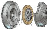
| Flywheel | 6 bolt mounting |
| Flywheel mounting bolts | M12x1.25 mm, length 26 mm |
| Valve stem seals | Toyota 90913-02090 intake Toyota 90913-02088 exhaust |
| Compression | from 13 bar, difference in neighboring cylinders max. 1 bar |
| Turnover XX | 750 – 800 min-1 |
| Tightening torque for threaded connections | candle - 25 Nm flywheel - 83 Nm clutch bolt - 30 Nm bearing cap - 57 Nm (main) and 39 Nm (rod) cylinder head - three stages 29 Nm, 49 Nm + 90° |
The Toyota manufacturer's manual recommends changing the oil after 15,000 km. In practice, this is done twice as often, or at least after passing 10,000 runs.
Design features
In its series, the 4A FE engine has average performance and has the following design features:
- in-line arrangement of 4 cylinders bored directly in the body of a cast-iron block without liners;
- two overhead camshafts according to the DOHC scheme for gas distribution control through 16 valves inside an aluminum cylinder head;
- belt drive of one camshaft, transmission of rotation from it to the second camshaft by a gear wheel;
- distributor distribution of ignition from one coil, with the exception of later versions of the LB, in which each pair of cylinders had its own coil according to the DIS-2 scheme;
- engine options for low-octane LB fuel have less power and torque - 105 hp. With. and 139 Nm., respectively.

The motor does not bend the valves, like the entire A series, so you won’t have to do a major overhaul if the timing belt suddenly breaks.
List of engine modifications
There were three versions of the 4A FE power drive with the following design features:
- Gen 1 - produced in the period 1987 - 1993, had a capacity of 100 - 102 hp. with., had electronic injection;
- Gen 2 - let in in 1993 - 1998, had a power of 100 - 110 hp. c, the injection scheme, SHPG, intake manifold have changed, the cylinder head has been modernized for new camshafts, valve cover fins have been added;
- Gen 3 - years of production 1997 - 2001, power increased to 115 hp. With. by changing the geometry of the intake and exhaust manifolds, the internal combustion engine was used only for domestic cars.

Replaced the management of the company with the 4A FE motor with a new family of 3ZZ FE power drives.
Advantages and disadvantages
The main advantage of the 4A FE design is the fact that the piston does not bend the valve when the timing belt breaks. The rest of the advantages are:
- availability of spare parts;
- low operating budget;
- high resource;
- the possibility of self-repair / maintenance, since attachments do not interfere with this;
The main disadvantage is the LeanBurn system - in the domestic market of Japan, such machines are considered very economical, especially in traffic jams. They are practically unsuitable for RF gasoline, since at medium speeds there is a power failure, which cannot be cured. Motors become sensitive to the quality of fuel and oil, the condition of high-voltage wires, tips and candles.

Due to the non-floating landing of the piston pin and increased wear of the camshaft beds, overhauls happen more often, but you can do it yourself. The manufacturer used high-life attachments, the power drive has three modifications, in which the volumes of the combustion chambers are preserved.
List of car models in which it was installed
Initially, the 4A FE engine was created exclusively for cars of the Japanese manufacturer Toyota:
- Carina - V generation in the back of the T170 sedan 1988 - 1990 and 1990 - 1992 (restyling), VI generation in the back of the T190 sedan 1992 - 1994 and 1994 - 1996 (restyling);
- Celica - V generation in the back of the T180 coupe 1989 - 1991 and 1991 - 1993 (restyling);
- Corolla (European market) - VI generation E90 hatchback and station wagon 1987 - 1992, VII generation E100 hatchback, sedan and station wagon 1991 - 1997, VIII generation E110 station wagon, hatchback and sedan 1997 - 2001;
- Corolla (Japanese domestic market) - 6th, 7th and 8th generation in the bodies of E90, E100 and E110 sedan / station wagon 1989 - 2001, respectively;
- Corolla (American market) - 6th and 7th generation in the bodies of the E90 and E100 station wagon, coupe and sedan 1988 - 1997, respectively;
- Corolla Ceres - I generation in the back of the E100 sedan 1992 - 1994 and 1994 - 1999 (restyling);
- Corolla FX - III generation in the back of an E10 hatchback;
- Corolla Levin - 6th and 7th generation in E100 and E100 coupe bodies 1991 - 2000;
- Corolla Spacio - I generation in the back of the E110 minivan 1997 - 1999 and 1999 - 2001 (restyling);
- Corona - IX and X generation in the bodies of T170 and T190 sedan 1987 - 1992 and 1992 - 1996, respectively;
- Sprinter Trueno - 6th and 7th generation in E100 and E110 coupe bodies 1991 - 1995 and 1995 - 2000, respectively;
- Sprinter Marino - I generation in the back of the E100 sedan 1992 - 1994 and 1994 - 1997 (restyling);
- Sprinter Carib - II and III generation in the bodies of the E90 and E110 station wagon 1988 - 1990 and 1995 - 2002, respectively;
- Sprinter - 6th, 7th and 8th generations in the bodies of AE91, U100 and E110 sedan 1989 - 1991, 1991 - 1995 and 1995 - 2000, respectively;
- Premio - I generation in the back of the T210 sedan 1996 - 1997 and 1997 - 2001 (restyling).

This motor was used in Toyota AE86, Caldina, Avensis and MR2, engine characteristics allowed them to be equipped with Geo Prizm, Chevrolet Nova and Elfin Type 3 Clubman cars.
Service schedule 4A FE 1.6 l / 110 l. With.
The 4A FE in-line gasoline engine must be serviced at the following times:
- the engine oil resource is 10,000 km, then the lubricant and filter must be replaced;
- the fuel filter must be replaced after 40,000 runs, the air filter twice as often;
- battery life is set by the manufacturer, on average it is 50 - 70 thousand km;
- candles should be changed after 30,000 km, and checked annually;
- crankcase ventilation and adjustment of thermal valve clearances are carried out at the turn of 30,000 car mileage;
- antifreeze is replaced after 50,000 km, hoses and a radiator must be inspected constantly;
- the exhaust manifold can burn out after 100,000 km of run.

Initially, a simple ICE device allows you to carry out maintenance and repairs on your own in the garage.
Overview of faults and how to fix them
Due to the design features, the 4A FE motor is subject to the following "diseases":
| Knocking inside the engine | 1) with high mileage, piston pin wear 2) with a slight violation of the thermal clearances of the valves | 1) replacement fingers 2) gap adjustment |
| Increasing oil consumption | production of valve stem seals or rings | diagnostics and replacement of consumables |
| Engine starts and stops | fuel system malfunction | cleaning injectors, distributor, fuel pump, replacing the fuel filter |
| floating speed | clogging of crankcase ventilation, throttle valve, injectors, IAC wear | cleaning and replacing spark plugs, injectors, idle speed regulator |
| Increased vibration | blockage of nozzles or candles | replacing injectors, spark plugs |

Gaps with idle speed and engine start occur after the sensors have run out of service life or have been damaged. Due to a burned-out lambda probe, fuel consumption may increase and soot can form on candles. On some Toyota cars, engines with the Lean Burn system were installed. Owners can fill in gasoline with a low octane number, but the overhaul period is reduced by 30 - 50%.
Motor tuning options
Within Toyota's powertrain series, the 4A FE engine is considered unsuitable for retrofit. Usually tuning is done for versions 4A GE, which, by the way, has a turbocharged up to 240 hp. With. analog. Even when installing a turbo kit on a 4A FE, you get a maximum of 140 hp. with., which is incommensurable with the initial investment.
However, atmospheric tuning is possible in the following way:
- reduction in the compression ratio due to the replacement of the crankshaft and BHPG;
- cylinder head grinding, increase in the diameter of valves and seats;
- use of high-performance nozzles and pump;
- replacing camshafts with products with a longer valve opening phase.

In this case, tuning will provide the same 140 - 160 hp. with., but without reducing the operational life of the engine.
Thus, the 4A FE motor does not bend the valves, has a high resource of 250,000 km and a base power of 110 hp. with., which is artificially lowered on the conveyor for some car models.
If you have any questions - leave them in the comments below the article. We or our visitors will be happy to answer them.
The first digit in the modern coding of Toyota engines shows the serial number of the modification, i.e. the first (base) motor is marked1 A, Athe first modification of this motor - 2A , the next modification is called3A and finally 4 A (under "modification" is meant the release of a motor of a different volume based on an existing motor).
Family A originated in 1978 year, motor 1A had volume 1.5 L(piston diameter 77.5mm., stroke 77.0mm), the main goals of creation were: compactness, low noise level, environmental friendliness, good torque characteristics and no need for maintenance.Various engine options 4A issued from 1982 By 2002 , in the Toyota lineup, this engine took the place of the "venerable old man" (with Hemi head by the way), and he himself was later replaced by a much less successful. I reflected all the brightness of engineering thought over the past 40 years in a tablet:
| 2T- C | 4A -C | 3ZZ-FE | |
| Volume | 1588 cm3 | 1587 cm3 | 1598 cm3 |
| Bore/stroke | 85mm \ 70mm | 81mm\77mm | 79mm \ 85.1mm |
| Compression ratio | 8.5:1 | 9.0:1 | 10:1 |
|
Max. power (rpm) Max. moment (rpm) |
88 hp (6000) 91 Nm (3800) |
90 hp (4800) 115 (2800) |
109 hp (6000) 150 (3800) |
| Camshaft \ hydraulic lifters | OHV \ no | SOHC \ no | DOHC \ no |
| Timing drive | Chain | Belt | Chain |
| Estimated service life | 450 t.km. | 300 t.km. | 210 t.km |
| Years of production (whole family) | 1970-1985 | 1982 -2002 | 2000 - 2006 |
As you can see, engineers are able to raise the compression ratio, reduce durability, and gradually made a more “compact” long-stroke engine from a short-stroke engine ...
I had personally in operation and repair (carburetor with 8 valves and 17 tubes to the carburetor and various pneumatic valves that you can’t buy anywhere) I can’t say anything good about it - the valve guide broke in the head, you can’t buy it separately, which means replacement heads (only, where can I find an 8-valve head?). It is better to change the crankshaft than to sharpen it - I had it only 30 thousand after boring to the first repair size. The oil receiver is not at all successful (the grid is closed by a casing, in which there is one hole from the bottom, the size of a penny coin) - it clogged with some kind of nonsense, which caused the engine to knock ...
 The oil pump is made even more interesting: the design of almost 3 parts and a valve is mounted in the front cover of the engine, which is put on the crankshaft (by the way, the front crankshaft oil seal is difficult to change). Actually, the oil pump is driven by the front end of the crankshaft. I specifically looked at the Toyota engines of those years of the series R,T And K, well, or the next series S And G- nowhere has such a solution (oil pump driven by the front end of the crankshaft directly or through a gear) ever been used! From my college days, I still remember a Russian book on engine design, which said why this should not be done (I hope the smart ones know themselves, but I’ll only tell fools for money).
Okay, let's understand the marking of engines: the letter WITH after the dash meant the presence of an emission control system ( C not used if the engine was originally equipped for emission control, due C with California, then only there were strict emission standards),
Letter E after the dash meant distributed fuel injection (Electronic fuel injection - EFI), imagine, an injector on an 8-valve Toyota engine! I hope you never see this again! (I put it on AE82, if anyone is interested).
/ . Letter L after the dash meant that the engine is installed on the car across, and the letter U(from Unleaded fuel) that the emission control system was designed for gasoline, available in those years only in Japan.
Luckily, you won't find 8-valve A-series engines anymore, so let's talk about 16-valve and 20-valve engines. Their distinguishing feature is the presence in the name of the engine after the dash of the letter F(an engine of a standard power range with four valves per cylinder, or as marketers came up with - High Efficiency Twincam Engine), for such engines, only one camshaft is driven by a timing belt or chain, while the second is driven from the first through a gear (engines with so called narrow cylinder head), for example 4A-F. Or letters G- this is an engine, each of the camshafts of which has its own drive from the timing belt (chain). Toyota marketers call these engines High Performance Engine, and their camshafts are driven through their own gears (with a wide cylinder head).
Letter T meant the presence of turbocharging (Turbocharged), and the letter Z (Supercharged) - a mechanical supercharger (compressor).
- a good choice to buy, only if it is not equipped with a system LEAN BURN:
 When the belt breaks, the valves in the engine bend!
The 4A-FE LEAN BURN (LB) engine differs from the conventional 4A-FE in the design of the cylinder head, where four of the eight intake ports have a lip to form cylinder inlet swirls. Fuel injectors are installed directly in the cylinder head and inject fuel into the intake valve area. Injection is carried out alternately by each nozzle (according to a sequential scheme).
On most LB engines of the second half of the 90s, a DIS-2 (Direct Ignition System) type ignition system was used, with 2 ignition coils and special spark plugs with platinum-coated electrodes.
In the LB scheme of European models, a new type of oxygen sensors (Lean Mixture Sensor) is used, which are significantly more expensive than conventional ones, and at the same time do not have inexpensive analogues. In the scheme for the Japanese market, a conventional lambda probe is used.
Between the intake manifold and the cylinder head, a pneumatically controlled damper system is installed.  The valve flaps are actuated by a vacuum supplied to the common pneumatic actuator using an electro-pneumatic valve at the signal of the electronic control unit (ECU) depending on the degree of throttle opening and speed.
As a result, the differences between 4A-FE LB and 4A-FE simple:
1. The ignition coil is removed from the distributor (ignition distributor) to the wall of the engine compartment.
2. There is no knock sensor.
3. The nozzles are not located on the intake manifold, but on the head and inject the fuel mixture almost immediately before the intake valve.
4. At the junction of the intake manifold and the head of the block there are additional controlled dampers.
5. Nozzles work alternately, all four, and not in pairs.
6. Candles should only be platinum.

- installed only on some modifications of CARINA E-AT171, SPRINTER CARIB E-AE95G, SPRINTER CARIB E-AE95G<4WD>- there are a lot of engines at disassembly, it’s better to take a contract right away, and don’t try to fix the old one!
Number of cylinders, layout, timing type, number of valves: R4; DOHC, 16Valve;
Engine displacement, cm3 (Displacement (cc)): 1587;
Engine power, hp / rpm: 115/6000;
Torque, Nm / rpm: 101/4400;
Compression Ratio: 9.50;
Bore (Bore) / Stroke (Stroke), mm: 81.0/77.0
The originals who are not looking for easy ways may well like the compressor version of this engine, it was placed on:
 COROLLA LEVIN -CERES E-AE101, COROLLA LEVIN -CERES E-AE92, MR-2 E-AW11, MR-2 E-AW11, SPRINTER TRUENO-MARINO E-AE101
Engine Model: 4A-GZE,
Number of cylinders, layout, timing type, number of valves: R4; DOHC, 16Valve;
Engine capacity, cm3: 1587;
Engine power, hp / rpm: 145/6400;
Torque, Nm / rpm: 140/4000;
Compression ratio: 8.00;
Diameter / Stroke, mm: 81.0/77.0
You can easily find the engine at dismantling sites, the only problem is that the MR2 has its own engine, which is not interchangeable with the rest.
Okay, you can talk about these engines for a long time, but some kind of conclusion is needed: I am glad that I managed to get acquainted with the design of this engine, it was far ahead of its time, and its design is in many ways better than later Toyota engines, although it even managed to I don’t consider it successful to spoil the environmental theme and the design of the oil pump and oil receiver a little. But, after all, engineers were not obliged to create an engine that would outlive the body ... I would not recommend you buying a Toyota with this engine, simply because the car as a whole will turn out to be garbage (although Audi, Mercedes and even Mazda of the same years, maybe they will drive more cheerfully) - there's nothing to be done, apparently, the real slogan of Toyota is "no more is needed, most importantly, the fence should be even!"
Well, and the last, the full history of Serie A:
Reliable Japanese engines
04.04.2008
The most common and by far the most widely repaired of Japanese engines is the Toyota 4, 5, 7 A - FE series engine. Even a novice mechanic, diagnostician knows about the possible problems of engines of this series.
I will try to highlight (collect into a single whole) the problems of these engines. There are few of them, but they cause a lot of trouble to their owners.
Date from scanner:

On the scanner, you can see a short but capacious date, consisting of 16 parameters, by which you can really evaluate the operation of the main engine sensors.
Sensors:
Oxygen sensor - Lambda probe

Many owners turn to diagnostics due to increased fuel consumption. One of the reasons is a banal break in the heater in the oxygen sensor. The error is fixed by the control unit code number 21.
The heater can be checked with a conventional tester on the sensor contacts (R- 14 Ohm)

Fuel consumption increases due to the lack of correction during warm-up. You will not be able to restore the heater - only a replacement will help. The cost of a new sensor is high, and it makes no sense to install a used one (their operating time is large, so this is a lottery). In such a situation, less reliable universal NTK sensors can be installed as an alternative.
The term of their work is short, and the quality leaves much to be desired, so such a replacement is a temporary measure, and it should be done with caution.

When the sensor sensitivity decreases, fuel consumption increases (by 1-3 liters). The operability of the sensor is checked by an oscilloscope on the diagnostic connector block, or directly on the sensor chip (number of switching).

temperature sensor
If the sensor does not work correctly, the owner will have a lot of problems. If the measuring element of the sensor breaks, the control unit replaces the sensor readings and fixes its value by 80 degrees and fixes error 22. The engine, with such a malfunction, will operate normally, but only while the engine is warm. As soon as the engine cools down, it will be problematic to start it without doping, due to the short opening time of the injectors.
There are frequent cases when the resistance of the sensor changes randomly when the engine is running at H.X. - the revolutions will float.

This defect is easy to fix on the scanner, observing the temperature reading. On a warm engine, it should be stable and not randomly change values from 20 to 100 degrees.

With such a defect in the sensor, a “black exhaust” is possible, unstable operation on H.X. and, as a result, increased consumption, as well as the inability to start "hot". Only after 10 minutes of sludge. If there is no complete confidence in the correct operation of the sensor, its readings can be replaced by including a 1 kΩ variable resistor or a constant 300 ohm resistor in its circuit for further verification. By changing the readings of the sensor, the change in speed at different temperatures is easily controlled.
Throttle position sensor

A lot of cars go through the process of assembly and disassembly. These are the so-called "constructors". When removing the engine in the field and subsequent assembly, the sensors suffer, on which the engine is often leaned. When the TPS sensor breaks, the engine stops throttling normally. The engine bogs down when revving. The machine switches incorrectly. Error 41 is fixed by the control unit. When replacing a new sensor, it must be adjusted so that the control unit correctly sees the sign of X.X., with the gas pedal fully released (throttle closed). In the absence of a sign of idling, adequate regulation of H.X. will not be carried out. and there will be no forced idling mode during engine braking, which again will entail increased fuel consumption. On engines 4A, 7A, the sensor does not require adjustment, it is installed without the possibility of rotation.
THROTTLE POSITION……0%
IDLE SIGNAL……………….ON
MAP absolute pressure sensor

This sensor is the most reliable of all installed on Japanese cars. His resilience is simply amazing. But it also has a lot of problems, mainly due to improper assembly.
Either the receiving “nipple” is broken, and then any passage of air is sealed with glue, or the tightness of the supply tube is violated.

With such a gap, fuel consumption increases, the level of CO in the exhaust increases sharply up to 3%. It is very easy to observe the operation of the sensor on the scanner. The line INTAKE MANIFOLD shows the vacuum in the intake manifold, which is measured by the MAP sensor. When the wiring is broken, the ECU registers error 31. At the same time, the opening time of the injectors sharply increases to 3.5-5ms. and stop the engine.
Knock sensor
The sensor is installed to register detonation knocks (explosions) and indirectly serves as a "corrector" of the ignition timing. The recording element of the sensor is a piezoelectric plate. In the event of a sensor malfunction, or a break in the wiring, at over 3.5-4 tons of revs, the ECU fixes error 52. Sluggishness is observed during acceleration.
You can check the performance with an oscilloscope, or by measuring the resistance between the sensor output and the housing (if there is resistance, the sensor needs to be replaced).

crankshaft sensor
On 7A series engines, a crankshaft sensor is installed. A conventional inductive sensor is similar to the ABC sensor and is practically trouble-free in operation. But there are also confusions. With an interturn circuit inside the winding, the generation of pulses at a certain speed is disrupted. This manifests itself as a limitation of engine speed in the range of 3.5-4 tons of revolutions. A kind of cut-off, only at low speeds. It is quite difficult to detect an interturn circuit. The oscilloscope does not show a decrease in the amplitude of the pulses or a change in frequency (during acceleration), and it is quite difficult for a tester to notice changes in Ohm's shares. If you experience symptoms of speed limit at 3-4 thousand, simply replace the sensor with a known good one. In addition, a lot of trouble causes damage to the master ring, which is damaged by negligent mechanics while replacing the front crankshaft oil seal or timing belt. Having broken the teeth of the crown, and restored them by welding, they achieve only a visible absence of damage.
At the same time, the crankshaft position sensor ceases to adequately read information, the ignition timing begins to change randomly, which leads to loss of power, unstable engine operation and increased fuel consumption

Injectors (nozzles)

During many years of operation, the nozzles and needles of the injectors are covered with tar and gasoline dust. All this naturally interferes with the correct spray and reduces the performance of the nozzle. With severe pollution, a noticeable shaking of the engine is observed, fuel consumption increases. It is realistic to determine clogging by conducting a gas analysis; according to the readings of oxygen in the exhaust, one can judge the correctness of filling. A reading above one percent will indicate the need to flush the injectors (with the correct timing and normal fuel pressure).
Or by installing the injectors on the stand, and checking the performance in the tests. Nozzles are easily cleaned by Lavr, Vince, both on CIP machines and in ultrasound.


The valve is responsible for engine speed in all modes (warm-up, idling, load). During operation, the valve petal becomes dirty and the stem is wedged. Turnovers hang on warming up or on X.X. (due to the wedge). Tests for changes in speed in scanners during diagnostics for this motor are not provided. The performance of the valve can be assessed by changing the readings of the temperature sensor. Enter the engine in the "cold" mode. Or, having removed the winding from the valve, twist the valve magnet with your hands. Jamming and wedge will be felt immediately. If it is impossible to easily dismantle the valve winding (for example, on the GE series), you can check its operability by connecting to one of the control outputs and measuring the duty cycle of the pulses while simultaneously controlling the RPM. and changing the load on the engine. On a fully warmed-up engine, the duty cycle is approximately 40%, by changing the load (including electrical consumers), an adequate increase in speed in response to a change in duty cycle can be estimated. When the valve is mechanically jammed, a smooth increase in the duty cycle occurs, which does not entail a change in the speed of H.X.
You can restore work by cleaning soot and dirt with a carburetor cleaner with the winding removed.

Further adjustment of the valve is to set the speed X.X. On a fully warmed up engine, by rotating the winding on the mounting bolts, they achieve tabular revolutions for this type of car (according to the tag on the hood). Having previously installed the jumper E1-TE1 in the diagnostic block. On the “younger” 4A, 7A engines, the valve has been changed. Instead of the usual two windings, a microcircuit was installed in the body of the valve winding. We changed the valve power supply and the color of the winding plastic (black). It is already pointless to measure the resistance of the windings at the terminals.
The valve is supplied with power and a control signal of a rectangular shape with a variable duty cycle.


To make it impossible to remove the winding, non-standard fasteners were installed. But the wedge problem remained. Now, if you clean it with an ordinary cleaner, the grease is washed out of the bearings (the further result is predictable, the same wedge, but already because of the bearing). It is necessary to completely dismantle the valve from the throttle body and then carefully flush the stem with the petal.
Ignition system. Candles.
A very large percentage of cars come to the service with problems in the ignition system. When operating on low-quality gasoline, spark plugs are the first to suffer. They are covered with a red coating (ferrosis). There will be no high-quality sparking with such candles. The engine will work intermittently, with gaps, fuel consumption increases, the level of CO in the exhaust rises. Sandblasting is not able to clean such candles. Only chemistry (silit for a couple of hours) or replacement will help. Another problem is the increase in clearance (simple wear).
Drying of the rubber lugs of high-voltage wires, water that got in when washing the motor, which all provoke the formation of a conductive path on the rubber lugs.


Because of them, sparking will not be inside the cylinder, but outside it.
With smooth throttling, the engine runs stably, and with a sharp one, it “crushes”.

In this situation, it is necessary to replace both the candles and the wires at the same time. But sometimes (in the field), if replacement is impossible, you can solve the problem with an ordinary knife and a piece of emery stone (fine fraction). With a knife we cut off the conductive path in the wire, and with a stone we remove the strip from the ceramics of the candle.
It should be noted that it is impossible to remove the rubber band from the wire, this will lead to the complete inoperability of the cylinder.

Another problem is related to the incorrect procedure for replacing candles. The wires are pulled out of the wells with force, tearing off the metal tip of the rein.

With such a wire, misfires and floating revolutions are observed. When diagnosing the ignition system, you should always check the performance of the ignition coil on the high-voltage arrester. The simplest test is to look at the spark gap on the spark gap with the engine running.

If the spark disappears or becomes filiform, this indicates an inter-turn short circuit in the coil or a problem in the high voltage wires. A wire break is checked with a resistance tester. Small wire 2-3k, then to increase the long 10-12k.


The closed coil resistance can also be checked with a tester. The resistance of the secondary winding of the broken coil will be less than 12 kΩ.
The next generation coils do not suffer from such ailments (4A.7A), their failure is minimal. Proper cooling and wire thickness eliminated this problem.
Another problem is the current oil seal in the distributor. Oil, falling on the sensors, corrodes the insulation. And when exposed to high voltage, the slider is oxidized (covered with a green coating). The coal turns sour. All this leads to disruption of sparking.
In motion, chaotic shootings are observed (into the intake manifold, into the muffler) and crushing.

" Thin " malfunctions Toyota engine
On modern Toyota 4A, 7A engines, the Japanese have changed the firmware of the control unit (apparently for faster engine warm-up). The change is that the engine reaches idle speed only at 85 degrees. The design of the engine cooling system was also changed. Now a small cooling circle intensively passes through the head of the block (not through the pipe behind the engine, as it was before). Of course, the cooling of the head has become more efficient, and the engine as a whole has become more efficient. But in winter, with such cooling during movement, the temperature of the engine reaches a temperature of 75-80 degrees. And as a result, constant warm-up revolutions (1100-1300), increased fuel consumption and nervousness of the owners. You can deal with this problem either by insulating the engine more strongly, or by changing the resistance of the temperature sensor (by deceiving the computer).
Oil
Owners pour oil into the engine indiscriminately, without thinking about the consequences. Few people understand that different types of oils are not compatible and, when mixed, form an insoluble porridge (coke), which leads to the complete destruction of the engine.

All this plasticine cannot be washed off with chemistry, it is cleaned only mechanically. It should be understood that if it is not known what type of old oil, then flushing should be used before changing. And more advice to the owners. Pay attention to the color of the oil dipstick handle. He is yellow. If the color of the oil in your engine is darker than the color of the pen, it's time to change instead of waiting for the virtual mileage recommended by the engine oil manufacturer.
Air filter
The most inexpensive and easily accessible element is the air filter. Owners very often forget about replacing it, without thinking about the likely increase in fuel consumption. Often, due to a clogged filter, the combustion chamber is very heavily polluted with burnt oil deposits, valves and candles are heavily contaminated.
When diagnosing, it can be erroneously assumed that the wear of the valve stem seals is to blame, but the root cause is a clogged air filter, which increases the vacuum in the intake manifold when contaminated. Of course, in this case, the caps will also have to be changed.


Some owners do not even notice that garage rodents live in the air filter housing. Which speaks of their complete disregard for the car.


Fuel filteralso deserves attention. If it is not replaced in time (15-20 thousand mileage), the pump starts to work with overload, the pressure drops, and as a result, it becomes necessary to replace the pump.
The plastic parts of the pump impeller and check valve wear out prematurely.

The pressure drops
It should be noted that the operation of the motor is possible at a pressure of up to 1.5 kg (with a standard 2.4-2.7 kg). At reduced pressure, there are constant shots into the intake manifold, the start is problematic (after). The draft is noticeably reduced. It is correct to check the pressure with a pressure gauge. (access to the filter is not difficult). In the field, you can use the "return filling test". If, when the engine is running, less than one liter flows out of the gasoline return hose in 30 seconds, it can be judged that the pressure is low. You can use an ammeter to indirectly determine the performance of the pump. If the current consumed by the pump is less than 4 amperes, then the pressure is squandered.
You can measure the current on the diagnostic block.

When using a modern tool, the process of replacing the filter takes no more than half an hour. Previously, this took a lot of time. Mechanics always hoped in case they were lucky and the bottom fitting did not rust. But often that is what happened.
I had to rack my brains for a long time with which gas wrench to hook the rolled-up nut of the lower fitting. And sometimes the process of replacing the filter turned into a “movie show” with the removal of the tube leading to the filter.

Today, no one is afraid to make this change.
Control block
Until 1998 release,
control units did not have enough serious problems during operation.

The blocks had to be repaired only for the reason"
hard polarity reversal"
. It is important to note that all conclusions of the control unit are signed. It is easy to find on the board the necessary sensor output for testing,
or wire ringing. The parts are reliable and stable in operation at low temperatures.
In conclusion, I would like to dwell a little on gas distribution. Many “hands on” owners perform the belt replacement procedure on their own (although this is not correct, they cannot properly tighten the crankshaft pulley). Mechanics make a quality replacement within two hours (maximum). If the belt breaks, the valves do not meet the piston and there is no fatal destruction of the engine. Everything is calculated to the smallest detail.
We tried to talk about the most common problems on Toyota A-series engines. The engine is very simple and reliable, and subject to very tough operation on “water-iron gasolines” and dusty roads of our great and mighty Motherland and the “maybe” mentality of the owners. Having endured all the bullying, to this day he continues to delight with his reliable and stable work, having won the status of the best Japanese engine.
I wish you all the earliest possible identification of problems and easy repair of the Toyota 4, 5, 7 A - FE engine!
Vladimir Bekrenev, Khabarovsk
Andrey Fedorov, Novosibirsk
© Legion-Avtodata
UNION OF AUTOMOBILE DIAGNOSTICS
Information on car maintenance and repair can be found in the book (books):

Engines 4A-F, 4A-FE, 5A-FE, 7A-FE and 4A-GE (AE92, AW11, AT170 and AT160) 4-cylinder, in-line, with four valves per cylinder (two intake, two exhaust ), with two overhead camshafts. 4A-GE engines are distinguished by the installation of five valves per cylinder (three intake two exhaust).
Engines 4A-F, 5A-F are carbureted. all other engines have an electronically controlled multiport fuel injection system.
4A-FE engines were made in three versions, which differed from each other mainly in the design of the intake and exhaust systems.
The 5A-FE engine is similar to the 4A-FE engine, but differs from it in the size of the cylinder-piston group. The 7A-FE engine has slight design differences from the 4A-FE. Engines will have cylinder numbering starting on the side opposite the power take-off. The crankshaft is full-support with 5 main bearings.
The bearing shells are made on the basis of an aluminum alloy and are installed in the bores of the engine crankcase and main bearing caps. Drillings made in the crankshaft are used to supply oil to the connecting rod bearings, connecting rod rods, pistons and other parts.
Cylinder firing order: 1-3-4-2.
The cylinder head, cast from an aluminum alloy, has transverse and located on opposite sides inlet and outlet pipes, arranged with tented combustion chambers.
The spark plugs are located in the center of the combustion chambers. The 4A-f engine uses a traditional intake manifold design with 4 separate pipes that are combined into one channel under the carburetor mounting flange. The intake manifold has liquid heating, which improves engine response, especially when it is warmed up. The intake manifold of 4A-FE, 5A-FE engines has 4 independent pipes of the same length, which, on the one hand, are connected by a common intake air chamber (resonator), and on the other, they are joined to the intake channels of the cylinder head.
The intake manifold of the 4A-GE engine has 8 of these pipes, each of which fits its own intake valve. The combination of the length of the intake pipes with the valve timing of the engine makes it possible to use the phenomenon of inertial boost to increase torque at low and medium engine speeds. The exhaust and intake valves are mated with springs that have an uneven winding pitch.
The exhaust camshaft of 4A-F, 4A-FE, 5A-FE, 7A-FE engines is driven from the crankshaft by a flat toothed belt, and the intake camshaft is driven from the exhaust camshaft by a gear train. In the 4A-GE engine, both shafts are driven by a flat toothed belt.
The camshafts have 5 bearings located between the valve lifters of each cylinder; one of these bearings is located at the front end of the cylinder head. Lubrication of the bearings and cams of the camshafts, as well as drive gears (for engines 4A-F, 4A-FE, 5A-FE), is carried out by the oil flow entering through the oil channel drilled in the center of the camshaft. Valve clearance adjustment is carried out using shims located between the cams and valve lifters (for twenty-valve 4A-GE engines, adjusting spacers are located between the tappet and valve stem).
The cylinder block is cast iron. it has 4 cylinders. The upper part of the cylinder block is covered by the cylinder head, and the lower part of the block forms the engine crankcase, in which the crankshaft is installed. The pistons are made of high temperature aluminum alloy. Recesses are made on the bottoms of the pistons to prevent the piston from meeting with the valves in the TMV.
The piston pins of the 4A-FE, 5A-FE, 4A-F, 5A-F and 7A-FE engines are "fixed" type: they are interference fit in the piston head of the connecting rod, but have a slip fit in the piston bosses. 4A-GE engine piston pins - "floating" type; they have a sliding fit in both the connecting rod piston head and the piston bosses. From axial displacement, such piston pins are fixed by retaining rings installed in the piston bosses.
The top compression ring is made of stainless steel (4A-F, 5A-F, 4A-FE, 5A-FE and 7A-FE engines) or steel (4A-GE engine) and the 2nd compression ring is made of cast iron. The oil scraper ring is made of an alloy of ordinary steel and stainless steel. The outer diameter of each ring is slightly larger than the diameter of the piston, and the elasticity of the rings allows them to tightly encircle the cylinder walls when the rings are installed in the piston grooves. Compression rings prevent the breakthrough of gases from the cylinder into the engine crankcase, and the oil scraper ring removes excess oil from the cylinder walls, preventing it from penetrating into the combustion chamber.
Maximum non-flatness:
-
4A-fe,5A-fe,4A-ge,7A-fe,4E-fe,5E-fe,2E…..0.05 mm
-
2C……………………………………………0.20 mm