All electronics repairers know the importance of having a lab power supply that can produce different voltages and currents for use in charging devices, powering circuits, testing circuits, etc. There are many varieties of such devices on the market, but experienced radio amateurs are quite capable of making a laboratory power supply with their own hands. For this, you can use used parts and housings, supplementing them with new elements.
simple device
The simplest power supply consists of only a few elements. Beginning radio amateurs will find it easy to design and assemble these lightweight circuits. The main principle is to create a rectifier circuit to obtain direct current. In this case, the output voltage level will not change, it depends on the transformation ratio.

The main components for a simple power supply circuit:
- A step-down transformer;
- rectifier diodes. You can turn them on in a bridge circuit and get full-wave rectification, or use a half-wave device with one diode;
- Capacitor for smoothing ripples. The electrolytic type is selected with a capacity of 470-1000 microfarads;
- Conductors for mounting the circuit. Their cross section is determined by the magnitude of the load current.
To design a 12-volt PSU, you need a transformer that would step down the voltage from 220 to 16 V, since the voltage decreases slightly after the rectifier. Such transformers can be found in used computer power supplies or purchased new. You can find recommendations on self-rewinding transformers, but at first it is better to do without it.
Diodes fit silicon. For devices of small power, ready-made bridges are on sale. It is important to connect them correctly.
This is the main part of the circuit, not yet quite ready for use. It is necessary to put an additional zener diode after the diode bridge to get a better output signal.

The resulting device is a conventional power supply without additional functions and is capable of supporting small load currents, up to 1 A. In this case, an increase in current can damage circuit components.
To get a powerful power supply, it is enough to install one or more amplifying stages on TIP2955 transistor elements in the same design.
Important! To ensure the temperature regime of the circuit on powerful transistors, it is necessary to provide cooling: radiator or ventilation.
Adjustable power supply
Power supplies with voltage regulation will help to solve more complex tasks. Commercially available devices vary in terms of control parameters, power ratings, etc. and are selected according to the intended use.
A simple adjustable power supply is assembled according to the exemplary scheme shown in the figure.

The first part of the circuit with a transformer, a diode bridge and a smoothing capacitor is similar to the circuit of a conventional power supply without regulation. As a transformer, you can also use the device from the old power supply, the main thing is that it matches the selected voltage parameters. This indicator for the secondary winding limits the regulating limit.
How the circuit works:
- The rectified voltage goes to the zener diode, which determines the maximum value of U (you can take 15 V). The limited current parameters of these parts require the installation of a transistor amplifying stage in the circuit;
- Resistor R2 is variable. By changing its resistance, you can get different values \u200b\u200bof the output voltage;
- If the current is also regulated, then the second resistor is installed after the transistor stage. It does not exist in this diagram.
If a different control range is required, a transformer with the appropriate characteristics must be installed, which will also require the inclusion of another zener diode, etc. The transistor needs radiator cooling.
Measuring instruments for the simplest regulated power supply will suit any: analog and digital.
Having built an adjustable power supply with your own hands, you can use it for devices designed for different operating and charging voltages.
Bipolar power supply
The device of a bipolar power supply is more complex. Experienced electronics engineers can engage in its design. Unlike unipolar ones, such PSUs at the output provide voltage with a “plus” and “minus” sign, which is necessary when powering amplifiers.

Although the circuit shown in the figure is simple, its implementation will require certain skills and knowledge:
- You will need a transformer with a secondary winding divided into two halves;
- One of the main elements are integrated transistor stabilizers: KR142EN12A - for direct voltage; KR142EN18A - for the reverse;
- A diode bridge is used to rectify the voltage, it can be assembled on separate elements or a ready-made assembly can be used;
- Resistors with variable resistance are involved in voltage regulation;
- For transistor elements, it is imperative to mount cooling radiators.
A bipolar laboratory power supply will also require the installation of monitoring devices. The assembly of the case is made depending on the dimensions of the device.
Power supply protection
The easiest way to protect the PSU is to install fuses with fusible links. There are self-recovery fuses that do not require replacement after a burnout (their resource is limited). But they do not provide a full guarantee. Often the transistor is damaged before the fuse blows. Radio amateurs have developed various circuits using thyristors and triacs. Options can be found online.
For the manufacture of the casing of the device, each master uses the methods available to him. With enough luck, you can find a ready-made container for the device, but you still have to change the design of the front wall in order to place control devices and control knobs there.

Some crafting ideas:
- Measure the dimensions of all components and cut out the walls from aluminum sheets. Mark the front surface and make the necessary holes;
- Fasten the structure with a corner;
- The lower base of the PSU with powerful transformers must be reinforced;
- For external processing, prime the surface, paint and fix with varnish;
- Circuit components are reliably isolated from external walls in order to avoid stress on the case during breakdown. To do this, it is possible to glue the walls from the inside with an insulating material: thick cardboard, plastic, etc.
Many devices, especially high power ones, require the installation of a cooling fan. It can be done with continuous operation, or a circuit can be made to automatically turn on and off when the specified parameters are reached.
The scheme is implemented by installing a temperature sensor and a microcircuit that provides control. For cooling to be effective, free air circulation is required. This means that the back panel, near which the cooler and radiators are mounted, must have holes.
Important! During the assembly and repair of electrical devices, one must be aware of the danger of electric shock. Capacitors that are energized must be discharged.
It is possible to assemble a high-quality and reliable laboratory power supply with your own hands if you use serviceable components, clearly calculate their parameters, use proven circuits and the necessary devices.
Video
This power supply on the LM317 chip does not require any special knowledge for assembly, and after proper installation from serviceable parts, it does not need to be adjusted. Despite its apparent simplicity, this unit is a reliable power source for digital devices and has built-in protection against overheating and overcurrent. The microcircuit has over twenty transistors inside and is a high-tech device, although from the outside it looks like an ordinary transistor.
The power supply of the circuit is designed for voltages up to 40 volts AC, and at the output you can get from 1.2 to 30 volts of constant, stabilized voltage. Adjustment from minimum to maximum with a potentiometer is very smooth, without jumps and dips. Output current up to 1.5 amperes. If the current consumption is not planned to be higher than 250 milliamps, then a radiator is not needed. When consuming a larger load, place the microcircuit on the heat-conducting paste to the radiator with a total dissipation area of 350 - 400 or more, millimeters square. The selection of a power transformer must be calculated based on the fact that the voltage at the input to the power supply should be 10 - 15% more than you plan to receive at the output. It is better to take the power of the supply transformer with a good margin, in order to avoid excessive overheating, and it is imperative to put a fuse selected for power at its input to protect against possible troubles.
For the manufacture of this necessary device, we need the following details:
- Chip LM317 or LM317T.
- Almost any rectifier assembly or separate four diodes for a current of at least 1 ampere each.
- Capacitor C1 from 1000 uF and higher with a voltage of 50 volts, it serves to smooth out surges in the mains voltage and the larger its capacitance, the more stable the output voltage will be.
- C2 and C4 - 0.047 uF. Number 104 on the cap of the capacitor.
- C3 - 1uF and more with a voltage of 50 volts. This capacitor can also be used with a larger capacity to increase the stability of the output voltage.
- D5 and D6 - diodes, for example 1N4007, or any other for a current of 1 ampere or more.
- R1 - potentiometer for 10 Kom. Any type, but always good, otherwise the output voltage will "jump".
- R2 - 220 ohms, power 0.25 - 0.5 watts.
Assembling an adjustable stabilized power supply
I made the assembly on a regular breadboard without any etching. I like this method because of its simplicity. Thanks to him, the scheme can be assembled in a matter of minutes.


Checking the power supply
By rotating the variable resistor, you can set the desired output voltage, which is very convenient.Every radio amateur, whether he is a teapot or even a professional, should have a sedate and important power supply on the edge of the table. I currently have two power supplies on my desk. One delivers a maximum of 15 Volts and 1 Amp (black arrow), and the other 30 Volts, 5 Amps (right):
Well, there is also a self-made power supply:

I think you often saw them in my experiments, which I showed in various articles.
I bought factory power supplies a long time ago, so they cost me inexpensively. But, at the present time, when this article is being written, the dollar is already breaking through the mark of 70 rubles. Crisis, his mother, has everyone and everything.
Okay, something went wrong ... So what am I talking about? Oh yes! I think not everyone's pockets are bursting with money ... Then why don't we assemble a simple and reliable power supply circuit with our little hands, which will be no worse than a purchased block? Actually, our reader did just that. I dug up a schematic and assembled the power supply myself:

It turned out very even nothing! So, further on his behalf…
First of all, let's figure out what this power supply is good for:
- the output voltage can be adjusted in the range from 0 to 30 volts
- you can set some current limit up to 3 Amperes, after which the block goes into protection (a very convenient function, whoever used it knows).
– very low level of ripple (DC output of the power supply is not much different from DC batteries and accumulators)
– protection against overload and incorrect connection
- on the power supply by means of a short circuit (short circuit) of the “crocodiles”, the maximum allowable current is set. Those. current limit, which you set with a variable resistor on an ammeter. Therefore overloads are not terrible. The indicator (LED) will work, indicating that the set current level is exceeded.
So, now about everything in order. The scheme has been circulating on the Internet for a long time (click on the image, it will open in a new window in full screen):

The numbers in circles are the contacts to which you need to solder the wires that will go to the radio elements.
Designation of circles in the diagram:
- 1 and 2 to the transformer.
- 3 (+) and 4 (-) DC output.
- 5, 10 and 12 on P1.
- 6, 11 and 13 on P2.
- 7 (K), 8 (B), 9 (E) to transistor Q4.
Inputs 1 and 2 are supplied with an alternating voltage of 24 Volts from the mains transformer. The transformer must be of decent size so that it can deliver up to 3 Amperes to the load into a light one. You can buy it, or you can wind it).
Diodes D1 ... D4 are connected in a diode bridge. You can take diodes 1N5401 ... 1N5408 or some others that can withstand direct current up to 3 Amperes and above. You can also use a ready-made diode bridge, which would also withstand direct current up to 3 Amperes and above. I used the KD213 tablet diodes:

Chips U1,U2,U3 are operational amplifiers. Here is their pinout (pinout). View from above:

On the eighth output, “NC” is written, which indicates that this output does not need to be hooked anywhere. Neither a minus nor a plus of food. In the circuit, conclusions 1 and 5 also do not cling anywhere.
Transistor Q1 brand BC547 or BC548. Below is its pinout:

Transistor Q2 take better Soviet, brand KT961A

Don't forget to put it on the radiator.
Transistor Q3 brand BC557 or BC327

Transistor Q4 must be KT827!

Here is his pinout:

I didn’t redraw the circuit, so there are elements that can be confusing - these are variable resistors. Since the power supply circuit is Bulgarian, their variable resistors are designated as follows:
We have it like this:

I even pointed out how to find out its conclusions using the rotation of the column (twist).
Well, actually, the list of elements:
R1 = 2.2 kOhm 1W
R2 = 82 ohm 1/4W
R3 = 220 ohm 1/4W
R4 = 4.7 kOhm 1/4W
R5, R6, R13, R20, R21 = 10 kΩ 1/4W
R7 = 0.47 ohm 5W
R8, R11 = 27 kOhm 1/4W
R9, R19 = 2.2 kOhm 1/4W
R10 = 270 kOhm 1/4W
R12, R18 = 56kΩ 1/4W
R14 = 1.5 kOhm 1/4W
R15, R16 = 1 kΩ 1/4W
R17 = 33 ohm 1/4W
R22 = 3.9 kOhm 1/4W
RV1 = 100K multi-turn trimmer
P1, P2 = 10KOhm linear potentiometer
C1 = 3300uF/50V electrolytic
C2, C3 = 47uF/50V electrolytic
C4 = 100nF
C5 = 200nF
C6 = 100pF ceramic
C7 = 10uF/50V electrolytic
C8 = 330pF ceramic
C9 = 100pF ceramic
D1, D2, D3, D4 = 1N5401…1N5408
D5, D6 = 1N4148
D7, D8 = 5.6V zener diodes
D9, D10 = 1N4148
D11 = 1N4001 diode 1A
Q1 = BC548 or BC547
Q2 = KT961A
Q3 = BC557 or BC327
Q4 = KT 827A
U1, U2, U3 = TL081, operational amplifier
D12 = LED
Now I will tell you how I collected it. The transformer has already taken ready from the amplifier. The voltage at its outputs was about 22 volts. Then he began to prepare the case for my PSU (power supply)

pickled


laundered the toner

drilled holes:

I soldered the cribs for the op amps (operational amplifiers) and all other radio elements, except for two powerful transistors (they will lie on the radiator) and variable resistors:

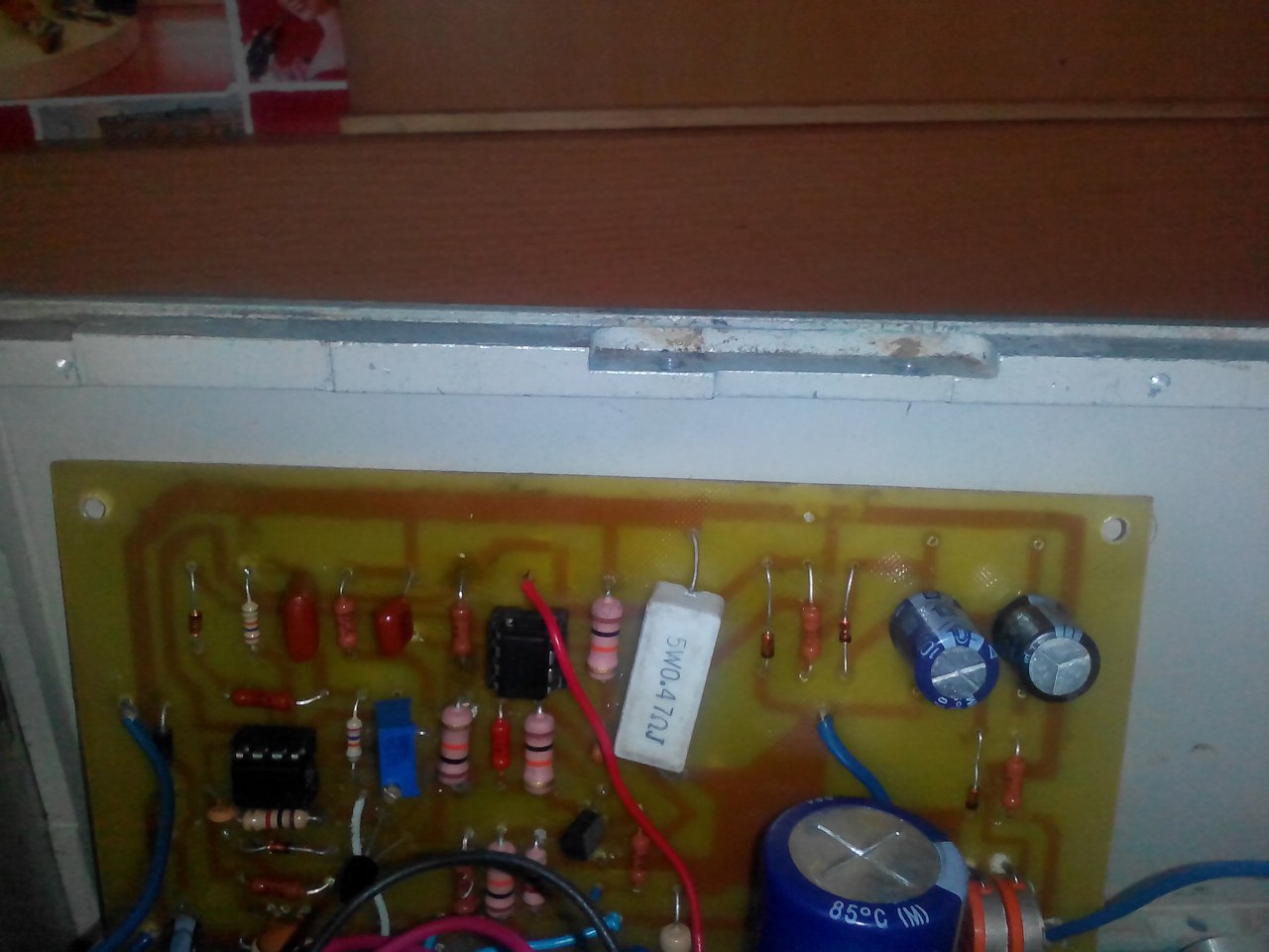
And this is what the board looks like with the full installation:

We prepare a place for a scarf in our case:
We attach a radiator to the case:

Do not forget about the cooler that will cool our transistors:

Well, after locksmith work, I got a very pretty power supply. So what do you think?

I took the description of the work, the signet and the list of radio elements at the end of the article.
Well, if anyone is too lazy to bother, then you can always buy a similar kit of this scheme for a penny on Aliexpress at this link


From the article you will learn how to make a do-it-yourself adjustable power supply from available materials. It can be used to power household equipment, as well as for the needs of your own laboratory. A DC voltage source can be used to test devices such as a car alternator relay-regulator. After all, when diagnosing it, there is a need for two voltages - 12 Volts and over 16. Now consider the design features of the power supply.
Transformer
If the device is not planned to be used for charging acid batteries and powering powerful equipment, then there is no need to use large transformers. It is enough to apply models whose power is not more than 50 watts. True, in order to make an adjustable power supply with your own hands, you will need to slightly change the design of the converter. First of all, you need to decide what range of voltage change will be at the output. The characteristics of the power supply transformer depend on this parameter.
Let's say you have chosen a range of 0-20 Volts, which means that you need to build on these values. The secondary winding should have an alternating voltage of 20-22 Volts at the output. Therefore, you leave the primary winding on the transformer, and wind the secondary winding on top of it. To calculate the required number of turns, measure the voltage, which is obtained from ten. A tenth of this value is the voltage obtained from one turn. After the secondary winding is done, it is necessary to assemble and tie the core.
Rectifier

As a rectifier, you can use both assemblies and individual diodes. Before you make an adjustable power supply, select all its components. If the output is high, then you will need to use powerful semiconductors. It is advisable to install them on aluminum radiators. As for the circuit, only the bridge circuit should be preferred, since it has a much higher efficiency, less voltage loss during rectification. It is not recommended to use a half-wave circuit, since it is inefficient, there are many ripples at the output that distort the signal and are a source of interference for radio equipment .
Stabilization and adjustment block

For the manufacture of the stabilizer, it is most reasonable to use the LM317 microassembly. A cheap and affordable device for everyone, which will allow you to assemble a high-quality do-it-yourself power supply in a matter of minutes. But its application requires one important detail - efficient cooling. And not only passive in the form of radiators. The fact is that voltage regulation and stabilization occur according to a very interesting scheme. The device leaves exactly the voltage that is needed, but the excess entering its input is converted into heat. Therefore, without cooling, the microassembly is unlikely to work for a long time.
Take a look at the diagram, there is nothing super complicated in it. The assembly has only three outputs, the third is energized, the second is removed, and the first is necessary to connect to the minus of the power supply. But here a small feature arises - if you turn on resistance between the minus and the first output of the assembly, then it becomes possible to adjust the voltage at the output. Moreover, a do-it-yourself power supply can change the output voltage both smoothly and in steps. But the first type of adjustment is the most convenient, so it is used more often. For implementation, it is necessary to include a variable resistance of 5 kOhm. In addition, a constant resistor with a resistance of about 500 ohms is required between the first and second output of the assembly.
Current and voltage control unit
Of course, in order for the operation of the device to be as convenient as possible, it is necessary to control the output characteristics - voltage and current. A circuit of an adjustable power supply is being built in such a way that the ammeter is connected to the break in the positive wire, and the voltmeter is connected between the outputs of the device. But the question is different - what type of measuring instruments to use? The easiest option is to install two LED displays, to which you can connect a volt- and ammeter circuit assembled on a single microcontroller.

But you can mount a couple of cheap Chinese multimeters in an adjustable power supply, made with your own hands. Fortunately, they can be powered directly from the device. You can, of course, use dial indicators, only in this case it is necessary to calibrate the scale for
Device body
The case is best made of light but durable metal. Aluminum would be ideal. As already mentioned, the regulated power supply circuit contains elements that get very hot. Therefore, a radiator must be mounted inside the case, which can be connected to one of the walls for greater efficiency. It is desirable to have a forced airflow. For this purpose, you can use a thermal switch paired with a fan. They must be installed directly on the cooling radiator.
Hello dear friends. In my next article, I decided to show how a power supply was assembled with voltage and current regulation. I saw the scheme in Ak's video and decided to make myself the same device. There was no printed circuit board with video, I drew it myself, it will be lower. At first, I simply assembled the circuit by surface mounting, but for some reason it didn’t work for me the first time, I probably mixed up the conclusions of the transistors and assembled it again, but now it just couldn’t work.
Here is a diagram of the device.
The circuit is quite simple and does not need adjustment, all the details can be found in the old TV. But I did not disassemble the TV, since I had all these details, well, let's not deviate from the topic. I drew the PCB in Sprint-Layout_5.0. and transferred it to the board.


But for some reason I didn’t transfer well and had to finish drawing with a permanent marker. Then I threw it into the pickling solution.


When my board was etched, I washed it well with water, if it is not washed with water it will be sticky. I dried it, removed the toner with a solvent and that's what happened.


The thing I don't like is drilling holes in the board. Now the most interesting and easy begins - this is the tinning of the board.


After tinning, we need to remove all that is left of the flux, make it with a solvent, just wipe our board. Now we take the details, I found them in advance and insert them into the printed circuit board according to the diagram.


That's all, you can rejoice, the scheme is assembled. Here is the circuit board


And yet, in my picture there is no output capacitor, I did not put it because I did not find it.
Here is the list of details:
Two transistors kt818, kt815. Two electrolytic capacitors for 1000 microfarads (50-60 volts). Three fixed resistors for 820 ohms, 470 ohms, 24 k. Two variable resistors, the first from (4.7k-10k) and the second 84k. And another diode 1N4007. The video will tell you the rest.