Semiconductor based, significantly reducing its resistance when the temperature drops. Based on these data, you can measure the temperature understandable to microcontrollers.


The main material for the thermistor (negative tks* ) serve as polycrystalline oxide semiconductors ( metal oxides).
There is also a variety of thermistors (with positive tks* ) – posistors. They receive titanium coupled with barium ceramics And rare earth metals. Much increase resistance at temperature increase. Main application - temperature stabilization transistor devices.
Thermistor invented Samuel Reuben (Samuel Ruben ) V 1930 year.
Thermistors are used in microelectronics for control temperature, severe industry, mobile measuring devices, perform protection function switching power supplies from large charging currents of capacitors & etc.
Very common on computer components.
They allow you to measure the temperature of processors, power systems, chipsets, and other components. Quite reliable, although factory defects are not uncommon, when the temperature is shifted by several tens of degrees, or even in the red.
There are also thermistors with their own built-in heating. They are used to manually turn on the heating and send a signal from a resistor about a change in resistance, or to power supply control network (when disconnected, the resistor will stop heating and change resistance).
Forms And dimensions thermistors can be different (discs, beads, cylinders & etc ).
Main Features semiconductor thermistor are: tks* ,range workers temperatures, maximum permissible power scattering, nominal resistance.
Thermistors (most) hardy to various temperatures, mechanical, to wear and tear from time to time, and with a certain processing and to aggressive chemical environments.
* Temperature Coefficient of Resistance
The temperature sensor is one of the most commonly used devices. Its main purpose is to perceive the temperature and convert it into a signal. There are many different types of sensors. The most common of these are the thermocouple and the thermistor.
Kinds
Detection and measurement of temperature is a very important activity, it has many applications, from a simple household to an industrial one. A temperature sensor is a device that collects temperature data and displays it in a human-readable format. The temperature sensing market is showing continuous growth due to its R&D needs in the semiconductor and chemical industries.
Thermal sensors are mainly of two types:
- Contact. These are thermocouples, filled system thermometers, thermal sensors and bimetal thermometers;
- Contactless sensors. These infrared devices have a wide range of applications in the defense sector due to their ability to detect the thermal output of optical and infrared rays emitted by liquids and gases.
A thermocouple (bimetal device) consists of two different kinds of wires (or even twisted) together. The principle of operation of a thermocouple is based on the fact that the speeds at which two metals expand differ from each other. One metal expands more than the other and begins to bend around the metal that is not expanding.
A thermistor is a kind of resistor whose resistance is determined by its temperature. The latter is usually used up to 100°C whereas the thermocouple is designed for higher temperatures and is not as accurate. Thermocouple circuits provide millivolt outputs, while thermistor circuits provide high voltage output.
Important! The main advantage of thermistors is that they are cheaper than thermocouples. They can be bought literally for pennies, and they are easy to use.
Operating principle
Thermistors are usually sensitive and have different thermal resistance. In an unheated conductor, the atoms that make up the material tend to arrange themselves in the correct order, forming long rows. When a semiconductor is heated, the number of active charge carriers increases. The more charge carriers available, the more conductive the material has.
The curve of resistance and temperature always shows a non-linear characteristic. The thermistor works best in a temperature range of -90 to 130 degrees Celsius.
Important! The principle of operation of the thermistor is based on the basic correlation between metals and temperature. They are made from semiconductor compounds such as sulfides, oxides, silicates, nickel, manganese, iron, copper, etc., and can sense even slight temperature changes.
An electron pushed by an applied electric field can travel relatively long distances before colliding with an atom. The collision slows it down, so the electrical "resistance" will decrease. At higher temperatures, the atoms move more, and when a particular atom deviates somewhat from its usual "parked" position, it is more likely to collide with a passing electron. This "slowdown" manifests itself in the form of an increase in electrical resistance.
For information. When the material is cooled, the electrons settle on the lowest valence shells, become unexcited and, accordingly, move less. In this case, the resistance to the movement of electrons from one potential to another drops. As the temperature of the metal increases, the resistance of the metal to the flow of electrons increases.
Design features
By their nature, thermistors are analog and are divided into two types:
- metal (posistors),
- semiconductor (thermistors).
posistors
Far from any current conductors can be used as a material for thermistors, since certain requirements are imposed on these devices. The material for their manufacture must have a high TCS.
Copper and platinum are suitable for such requirements, apart from their high cost. In practice, copper samples of TCM thermistors are widely used, in which the linearity of the dependence of resistance on temperature is much higher. Their disadvantage is low resistivity, rapid oxidation. In this regard, copper-based thermal resistances are of limited use, not more than 180 degrees.
PTC thermistors are designed to limit current when heated from higher power dissipation. Therefore, they are placed in series in an alternating current circuit in order to reduce the current. They (literally any of them) get hot from too much current. These devices are used in a circuit protection device, such as a fuse, as a timer in the degaussing circuit of CRT monitor coils.
For information. What is a posistor? A device whose electrical resistance increases with its temperature is called a posistor (PTC).

Thermistors
A device with a negative temperature coefficient (this is when the higher the temperature, the lower the resistance) is called an NTC thermistor.
For information. All semiconductors have varying resistance as temperature increases or decreases. This shows their hypersensitivity.

NTC thermistors are widely used as inrush current limiters, self-adjusting overcurrent protections, and self-regulating heating elements. Usually these devices are installed in parallel in the AC circuit.
They can be found everywhere: in cars, airplanes, air conditioners, computers, medical equipment, incubators, hair dryers, electrical outlets, digital thermostats, portable heaters, refrigerators, stoves, stoves, and all sorts of appliances.
The thermistor is used in bridge circuits.
Specifications
Thermistors are used in charging batteries. Their main characteristics are:
- High sensitivity, temperature coefficient of resistance is 10-100 times that of metal;
- Wide operating temperature range;
- Small size;
- Easy to use, the resistance value can be selected between 0.1~100kΩ;
- Good stability;
- Strong overload.
The quality of an instrument is measured in terms of standard characteristics such as response time, accuracy, and resistance to changes in other physical environmental factors. Service life and measuring range are a few other important characteristics to consider when considering usage.

Application area
Thermistors are not very expensive and can be readily available. They provide fast response and are reliable to use. The following are examples of how the devices can be used.
Air temperature sensor
An automotive thermal sensor is an NTC thermistor, which itself is very accurate when properly calibrated. The gauge is usually located behind the grille or bumper of the car and must be very accurate as it is used to determine the cut-off point for automatic climate control systems. The latter are adjustable in increments of 1 degree.

Automotive thermal sensor
The thermistor is built into the motor winding. Typically, this sensor is connected to a temperature relay (controller) to provide "Automatic Temperature Protection". When the motor temperature exceeds the set value set in the relay, the motor will automatically shut down. For less critical applications, it is used to trigger an overtemperature alarm with indication.
fire detector
You can make your own fire fighting device. Assemble a circuit from a thermistor or bimetallic strips borrowed from a starter. Thus, you can cause an alarm based on the action of a homemade temperature sensor.

In electronics, you always have to measure something, like temperature. This task is best handled by a thermistor - an electronic component based on semiconductors. The instrument detects a change in the physical quantity and converts it into an electrical quantity. They are a kind of measure of the rising impedance of the output signal. There are two types of devices: for posistors, resistance also increases with increasing temperature, while for thermistors, on the contrary, it falls. These are elements that are opposite in action and identical in principle of operation.
Video
In electronics, there is always something to measure or evaluate. For example, temperature. Thermistors successfully cope with this task - electronic components based on semiconductors, the resistance of which changes depending on temperature.
Here I will not describe the theory of physical processes that occur in thermistors, but move closer to practice - I will introduce the reader to the designation of the thermistor on the diagram, its appearance, some varieties and their features.
On circuit diagrams, the thermistor is designated like this.

Depending on the scope and type of the thermistor, its designation on the diagram may be slightly different. But you will always identify it by the characteristic inscription t or t° .
The main characteristic of a thermistor is its TCR. TKS is temperature coefficient of resistance. It shows how much the resistance of the thermistor changes when the temperature changes by 1°C (1 degree Celsius) or 1 degree Kelvin.
Thermistors have several important parameters. I will not give them, this is a separate story.
The photo shows the thermistor MMT-4V (4.7 kOhm). If you connect it to a multimeter and heat it up, for example, with a hot air gun or a soldering iron tip, you can make sure that its resistance drops with increasing temperature.

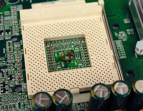
Thermistors are almost everywhere. Sometimes you are surprised that you did not notice them before, did not pay attention. Let's take a look at the board from the IKAR-506 charger and try to find them.

Here is the first thermistor. Since it is in an SMD package and has small dimensions, it is soldered to a small board and installed on an aluminum radiator - it controls the temperature of the key transistors.

Second. This is the so-called NTC thermistor ( JNR10S080L). I will talk about these more. It serves to limit the starting current. It's funny. It looks like a thermistor, but serves as a protective element.

For some reason, when it comes to thermistors, they usually think that they serve to measure and control temperature. It turns out that they have found application as protection devices.
Also, thermistors are installed in car amplifiers. Here is the thermistor in the Supra SBD-A4240 amplifier. Here it is involved in the protection circuit of the amplifier from overheating.

Here's another example. This is a DCB-145 lithium-ion battery from a DeWalt screwdriver. Or rather, his "offal". A measuring thermistor is used to control the temperature of the battery cells.

It's almost invisible. It is filled with silicone sealant. When the battery is assembled, this thermistor fits snugly against one of the Li-ion cells of the battery.
Direct and indirect heating.
According to the method of heating, thermistors are divided into two groups:
direct heating. This is when the thermistor is heated by external ambient air or current that flows directly through the thermistor itself. Directly heated thermistors are typically used for either temperature measurement or temperature compensation. Such thermistors can be found in thermometers, thermostats, chargers (for example, for Li-ion screwdriver batteries).
indirect heating. This is when the thermistor is heated by a nearby heating element. At the same time, he and the heating element are not electrically connected to each other. In such a case, the resistance of the thermistor is determined as a function of the current flowing through the heating element and not through the thermistor. Thermistors with indirect heating are combined devices.
NTC thermistors and posistors.
According to the dependence of the change in resistance on temperature, thermistors are divided into two types:
PTC thermistors (aka posistors).
Let's see what is the difference between them.
NTC thermistors got their name from the abbreviation NTC - Negative Temperature Coefficient , or "Negative Resistance Coefficient". The peculiarity of these thermistors is that when heated, their resistance decreases. By the way, this is how the NTC thermistor is indicated on the diagram.
Thermistor designation on the diagram
As you can see, the arrows on the designation are in different directions, which indicates the main property of the NTC thermistor: the temperature increases (up arrow), the resistance drops (down arrow). And vice versa.
In practice, you can meet an NTC thermistor in any switching power supply. For example, such a thermistor can be found in a computer power supply. We have already seen the NTC thermistor on the IKAR board, only there it was gray-green.
This photo shows an EPCOS NTC thermistor. It is used to limit the starting current.

For NTC thermistors, as a rule, its resistance at 25 ° C (for this thermistor it is 8 ohms) and the maximum operating current are indicated. Usually it's a few amps.
This NTC thermistor is installed in series, at the mains voltage input 220V. Take a look at the diagram.

Since it is connected in series with the load, all the current consumed flows through it. The NTC thermistor limits the inrush current that occurs due to the charge of the electrolytic capacitors (in diagram C1). An inrush of charging current can lead to a breakdown of the diodes in the rectifier (diode bridge on VD1 - VD4).
Each time the power supply is turned on, the capacitor begins to charge, and current begins to flow through the NTC thermistor. In this case, the resistance of the NTC thermistor is large, since it has not yet had time to heat up. The current flowing through the NTC thermistor heats it up. After that, the resistance of the thermistor decreases, and it practically does not interfere with the flow of current consumed by the device. Thus, due to the NTC thermistor, it is possible to ensure a "smooth start" of the electrical appliance and protect the rectifier diodes from breakdown.
It is clear that while the switching power supply is on, the NTC thermistor is in a "heated" state.
If any elements fail in the circuit, then the current consumption usually increases sharply. In this case, it is not uncommon for the NTC thermistor to serve as a kind of additional fuse and also fail due to the excess of the maximum operating current.


The failure of the key transistors in the power supply of the charger led to the excess of the maximum operating current of this thermistor (max 4A) and it burned out.
Posistors. PTC thermistors.
Thermistors, whose resistance increases with heating are called posistors. They are PTC thermistors (PTC - Positive Temperature Coefficient , "Positive Drag Factor").
It is worth noting that posistors are less widely used than NTC thermistors.
It is easy to find posistors on the board of any color CRT TV (with a kinescope). There it is installed in the degaussing circuit. In nature, there are both two-output posistors and three-output ones.
The photo shows a representative of a two-pin posistor, which is used in the kinescope demagnetization circuit.

Inside the case, between the spring leads, the working body of the posistor is installed. In fact, this is the posistor itself. Outwardly, it looks like a tablet with a contact layer sprayed on the sides.

As I said, posistors are used to demagnetize the kinescope, or rather its mask. Due to the magnetic field of the Earth or the influence of external magnets, the mask is magnetized, and the color image on the kinescope screen is distorted, spots appear.
Probably everyone remembers the characteristic sound "bdzin" when the TV is turned on - this is the moment when the degaussing loop works.
In addition to two-output posistors, three-output posistors are widely used. Like these ones.


Their difference from the two-output ones is that they consist of two “tablet” posistors, which are installed in one housing. In appearance, these "tablets" are exactly the same. But it's not. In addition to the fact that one tablet is slightly smaller than the other, their resistance in the cold state (at room temperature) is also different. One pill has a resistance of about 1.3 ~ 3.6 kΩ, while the other only has a resistance of 18 ~ 24 ohms.
Three-pin posistors are also used in the kinescope demagnetization circuit, like two-pin ones, but only the circuit for their inclusion is slightly different. If suddenly the posistor fails, and this happens quite often, then spots with an unnatural color display appear on the TV screen.
And capacitors. They are not marked, which makes them difficult to identify. In appearance, SMD thermistors are very similar to ceramic SMD capacitors.
Built-in thermistors.
In electronics, built-in thermistors are also actively used. If you have a soldering station with tip temperature control, then a thin-film thermistor is built into the heating element. Also, thermistors are built into the dryer of hot air soldering stations, but there it is a separate element.
It should be noted that in electronics, along with thermistors, thermal fuses and thermal relays (for example, KSD type) are actively used, which are also easy to detect in electronic devices.
Now that we have met with thermistors, it's time.
NTC and PTC thermistors
At the moment, the industry produces a huge range of thermistors, posistors and NTC thermistors. Each individual model or series is made for operation in certain conditions, certain requirements are imposed on them.
Therefore, a simple enumeration of the parameters of posistors and NTC thermistors will be of little use. We will go a slightly different way.
Every time you get your hands on a thermistor with easy to read markings, you need to find a reference sheet, or datasheet for this model of thermistor.
Who does not know what a datasheet is, I advise you to look at this page. In a nutshell, the datasheet contains information on all the main parameters of this component. This document lists everything you need to know to apply a particular electronic component.
I have this thermistor. Take a look at the photo. At first, I didn't know anything about him. Information was minimal. Judging by the marking, this is a PTC thermistor, that is, a posistor. On it and it is written - PTC. The following is the marking C975.

At first, it may seem that it is unlikely that it will be possible to find at least some information about this posistor. But don't hang your nose! We open the browser, we drive in Google a phrase like these: "posistor c975", "ptc c975", "ptc c975 datasheet", "ptc c975 datasheet", "posistor c975 datasheet". Then it remains only to find the datasheet for this posistor. As a rule, datasheets are issued as a pdf file.
From the found datasheet on PTC C975 I found out the following. It is produced by EPCOS. Full title B59975C0160A070(Series B599*5). This PTC thermistor is used for current limiting in case of short circuit and overload. Those. it's a kind of fuse.
I will give a table with the main technical characteristics for the B599 * 5 series, as well as a brief decoding of everything that all these numbers and letters stand for.


Now let's turn our attention to the electrical characteristics of a particular product, in our case it is the PTC C975 posistor (full marking B59975C0160A070). Take a look at the following table.

I R- Rated current (mA). Rated current. This is the current that this posistor can withstand for a long time. I would also call it a working, normal current. For the C975 thermistor, the rated current is just over half an ampere, specifically 550 mA (0.55A).
I S- Switching current (mA). Switching current. This is the amount of current flowing through the posistor, at which its resistance begins to increase sharply. Thus, if a current of more than 1100 mA (1.1A) begins to flow through the C975 posistor, then it will begin to perform its protective function, or rather, it will begin to limit the current flowing through itself due to an increase in resistance. Switching current ( I S) and reference temperature ( T ref) are connected, since the switching current causes the thermistor to heat up and its temperature reaches the level T ref, at which the resistance of the thermistor increases.
I Smax - maximum switching current (A). Maximum switching current. As you can see from the table, for this value, the value of the voltage across the posistor is also indicated - V=Vmax. This is no accident. The fact is that any posistor can absorb a certain amount of power. If it exceeds the allowable, then it will fail.
Therefore, the voltage is also indicated for the maximum switching current. In this case, it is equal to 20 volts. Multiplying 3 amps by 20 volts, we get a power of 60 watts. It is this power that our posistor can absorb when limiting the current.
Ir- residual current (mA). residual current. This is the residual current that flows through the posistor, after it has worked, it began to limit the current (for example, during overload). The residual current keeps the thermistor warm so that it is in a "hot" state and acts as a current limiter until the cause of the overload is removed. As you can see, the table shows the value of this current for different voltages on the posistor. One for maximum ( V=Vmax), another for nominal ( V=VR). It is not difficult to guess that by multiplying the limiting current by the voltage, we will get the power that is required to maintain the heating of the thesistor in the triggered state. for thermistor PTC C975 this power is 1.62~1.7W.
What's happened R R And Rmin The following chart will help us understand.

Rmin - Minimum resistance (Ohm). Minimum resistance. The smallest resistance value of the thermistor. The minimum resistance that corresponds to the minimum temperature after which the PTC range begins. If you study in detail the graphs for posistors, you will notice that up to the value T Rmin the resistance of the posistor, on the contrary, decreases. That is, a posistor at temperatures below T Rmin behaves like a "very bad" NTC thermistor and its resistance decreases (slightly) as the temperature rises.
R R - Rated resistance (Ohm). Rated resistance. This is the resistance of the posistor at some previously agreed temperature. Usually this 25°С(less often 20°С). Simply put, this is the thermistor resistance at room temperature, which we can easily measure with any multimeter.
Approvals - in literal translation, this is approval. That is, it is approved by such and such an organization that deals with quality control, etc. It is not particularly interested.
ordering code - serial number. Here, I think it's clear. Full labeling of the product. In our case, this is B59975C0160A070.
From the datasheet for the PTC C975 posistor, I learned that it can be used as a resettable fuse. For example, in an electronic device that consumes no more than 0.5A current at a supply voltage of 12V in operating mode.
Now let's talk about the parameters of NTC thermistors. Let me remind you that the NTC thermistor has a negative TCR. Unlike posistors, when heated, the resistance of an NTC thermistor drops sharply.
I had several NTC thermistors in stock. Basically, they were installed in power supplies and all kinds of power units. Their purpose is to limit the starting current. I settled on this thermistor. Let's find out its parameters.

On the case only the following marking is indicated: 16D-9 F1. After a short search on the Internet, I managed to find a datasheet for the entire series of MF72 NTC thermistors. Specifically, our instance is MF72-16D9. This series of thermistors is used to limit inrush current. The graph below shows how an NTC thermistor works.

At the initial moment when the device is turned on (for example, a laptop switching power supply, adapter, computer power supply, charger), the resistance of the NTC thermistor is high, and it absorbs the current pulse. Further, it warms up, and its resistance decreases several times.
While the device is operating and consuming current, the thermistor is in a heated state and its resistance is low.
In this mode, the thermistor has practically no resistance to the current flowing through it. As soon as the appliance is disconnected from the power source, the thermistor will cool down and its resistance will increase again.
Let's look at the parameters and main characteristics of the NTC thermistor MF72-16D9. Let's look at the table.

R25- Rated resistance of thermistor at 25°C (Ohm). Thermistor resistance at an ambient temperature of 25°C. This resistance is easy to measure with a multimeter. For the MF72-16D9 thermistor, this is 16 ohms. In fact R25- is the same as R R(Rated resistance) for the thermistor.
Max. Steady State Current - Maximum thermistor current (A). The maximum possible current through the thermistor that it can withstand for a long time. If the maximum current is exceeded, then an avalanche-like drop in resistance will occur.
Approx. R of Max. current- Thermistor resistance at maximum current (Ohm). The approximate resistance value of an NTC thermistor at maximum current flow. For the MF72-16D9 NTC thermistor, this resistance is 0.802 Ohm. This is almost 20 times less than the resistance of our thermistor at 25°C (when the thermistor is "cold" and not loaded with flowing current).
Dissip. Coef. - Energy sensitivity factor (mW/°C). In order for the thermistor's internal temperature to change by 1°C, it must absorb some power. The ratio of the absorbed power (in mW) to the temperature change of the thermistor shows this parameter. For our MF72-16D9 thermistor, this parameter is 11 milliwatts/1°C.
Let me remind you that when an NTC thermistor is heated, its resistance drops. To heat it up, the current flowing through it is consumed. Therefore, the thermistor will absorb power. The absorbed power leads to heating of the thermistor, and this in turn leads to a decrease in the resistance of the NTC thermistor by 10 to 50 times.
Thermal Time Constant - Cooling time constant (S). The time it takes for the unloaded thermistor temperature to change by 63.2% of the temperature difference between the thermistor itself and the environment. Simply put, this is the time during which the NTC thermistor has time to cool down after the current stops flowing through it. For example, when the power supply is disconnected from the mains.
Max. Load Capacitance in µF - Maximum Discharge Capacity . Test characteristic. Indicates the capacitance that can be discharged to an NTC thermistor through a terminating resistor in a test circuit without damaging it. Capacitance is specified in microfarads and for a specific voltage (120 and 220 volts alternating current (VAC)).
Tolerance of R 25 - Tolerance . Thermistor resistance tolerance at 25°C. Otherwise, this is a deviation from the nominal resistance R25. Usually the tolerance is ±10 - 20%.
That's all the main parameters of thermistors. Of course, there are other parameters that can be found in datasheets, but they are usually easily calculated from the main parameters.
I hope now, when you meet an electronic component unfamiliar to you (not necessarily a thermistor), it will be easy for you to find out its main characteristics, parameters and purpose.
The word "thermistor" is self-explanatory: A THERMAL RESISTOR is a device whose resistance changes with temperature.
Thermistors are highly non-linear devices and often have a wide range of parameters. That is why many, even experienced engineers and circuit designers, experience inconvenience when working with these devices. However, as you become more familiar with these devices, you can see that thermistors are actually quite simple devices.
First, it must be said that not all devices that change resistance with temperature are called thermistors. For example, resistance thermometers, which are made from small coils of twisted wire or from sputtered metal films. Although their parameters depend on temperature, however, they do not work like thermistors. Usually the term "thermistor" is used in relation to temperature-sensitive semiconductor devices.
There are two main classes of thermistors: NTC (Temperature Coefficient of Resistance) and PTC.
There are two fundamentally different types of PTC thermistors produced. Some are made like NTC thermistors, while others are made from silicon. PTC thermistors will be briefly described, with a focus on the more common NTC thermistors. Thus, if there are no special instructions, then we will talk about NTC thermistors.
NTC thermistors are highly sensitive, non-linear, narrow range devices whose resistance decreases with increasing temperature. Figure 1 shows a curve showing the change in resistance with temperature and is a typical temperature dependence of resistance. Sensitivity is approximately 4-5%/°C. There is a wide range of resistance values, and the change in resistance can reach many ohms and even kilo-ohms per degree.
R R oFig.1 NTC thermistors are very sensitive and largely
The degrees are non-linear. R o can be in ohms, kiloohms or megoohms:
1-resistance ratio R/R o; 2- temperature in o C
Essentially, thermistors are semiconductor ceramics. They are made from powders of metal oxides (usually oxides of nickel and manganese), sometimes with the addition of a small amount of other oxides. Powdered oxides are mixed with water and various binders to form batter, which is shaped and fired at temperatures in excess of 1000°C.A conductive metal coating (usually silver) is welded on and the leads are connected. The finished thermistor is usually coated with epoxy or glass, or encased in some other package.
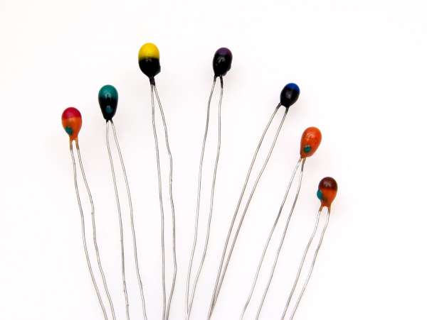
From fig. 2 it can be seen that there are many types of thermistors.
Thermistors are in the form of discs and washers with a diameter of 2.5 to approximately 25.5 mm, in the form of rods of various sizes.
Some thermistors are first made into large plates and then cut into squares. Very small bead thermistors are made by directly firing a drop of dough on two refractory titanium alloy leads and then dipping the thermistor into glass to form a coating.
Typical parameters
Saying "typical parameters" is not entirely correct, since there are only a few typical parameters for thermistors. There is an equally large number of specifications for a wide variety of thermistor types, sizes, shapes, ratings, and tolerances. Moreover, often thermistors from different manufacturers are not interchangeable.
You can buy thermistors with resistances (at 25 o C - the temperature at which the resistance of the thermistor is usually determined) from one ohm to ten megohms or more. The resistance depends on the size and shape of the thermistor, however, for each specific type, the resistance values can differ by 5-6 orders of magnitude, which is achieved by simply changing the oxide mixture. When the mixture is replaced, the form of the temperature dependence of the resistance also changes (R-T curve) and the stability at high temperatures also changes. Fortunately, thermistors with high resistance enough to be used at high temperatures also tend to be more stable.Inexpensive thermistors usually have fairly large parameter tolerances. For example, the allowable resistance values at 25 ° C vary in the range from ± 20% to ± 5%. At higher or lower temperatures, the spread of parameters increases even more. For a typical thermistor having a sensitivity of 4% per degree Celsius, the corresponding measured temperature tolerances vary from approximately ± 5° to ± 1.25° C at 25° C. High-precision thermistors will be discussed later in this article.
It was previously said that thermistors are narrow range devices. This needs to be clarified: most thermistors operate in the -80°C to 150°C range, and there are devices (usually glass-coated) that operate at 400°C and higher temperatures. However, for practical purposes, the greater sensitivity of thermistors limits their useful temperature range. The resistance of a typical thermistor can change by a factor of 10,000 or 20,000 at temperatures from -80°C to +150°C. One can imagine the difficulty in designing a circuit that can measure accurately at both ends of this range (unless range switching is used). Thermistor resistance, rated at zero degrees, will not exceed a few ohms at
Most thermistors use soldering to connect the leads internally. Obviously, such a thermistor cannot be used to measure temperatures above the melting point of the solder. Even without soldering, the epoxy coating of the thermistors is retained only at a temperature of no more than 200 ° C. For higher temperatures, it is necessary to use glass-coated thermistors with welded or fused leads.
Stability requirements also limit the use of thermistors at high temperatures. The structure of thermistors begins to change when exposed to high temperatures, and the rate and nature of the change is largely determined by the oxide mixture and the way the thermistor is manufactured. Some drift of epoxy coated thermistors begins at temperatures over 100°C or so. If such a thermistor is continuously operated at 150°C, then the drift can be measured by several degrees per year. Low-resistance thermistors (for example, no more than 1000 ohms at 25°C) are often even worse - they can be seen drifting when operating at about 70°C. And at 100°C they become unreliable.
Inexpensive devices with large tolerances are made with less attention to detail and can produce even worse results. On the other hand, some properly designed glass-coated thermistors have excellent stability even at higher temperatures. Glass-coated bead thermistors have very good stability, just like the recently introduced glass-coated disk thermistors. It should be remembered that the drift depends on both temperature and time. Thus, for example, it is generally possible to use an epoxy-coated thermistor for short-term heating to 150°C without significant drift.
When using thermistors, the nominal value must be taken into account constant power dissipation. For example, a small epoxy coated thermistor has a dissipation constant of one milliwatt per degree Celsius in still air. In other words, one milliwatt of power in a thermistor increases its internal temperature by one degree Celsius, and two milliwatts by two degrees, and so on. Applying a voltage of one volt to a one kiloohm thermistor with a dissipation constant of one milliwatt per degree Celsius results in a measurement error of one degree Celsius. Thermistors dissipate more power if they are immersed in liquid. The same small epoxy-coated thermistor mentioned above dissipates 8 mW/°C when in well-mixed oil. Large size thermistors have better constant dissipation than small devices. For example, a thermistor in the form of a disc or a washer can dissipate 20 or 30 mW / o C in air. It should be remembered that just as the thermistor's resistance changes with temperature, its dissipated power also changes.
Thermistor Equations
There is no exact equation to describe the behavior of a thermistor, only approximate ones. Consider two widely used approximate equations.
The first approximate equation, exponential, is quite satisfactory for limited temperature ranges, especially when using thermistors with low accuracy.