Good day. I present to your attention another review of the charger for smartphones that support wireless charging using Qi technology. The review will contain photos of the opened device and recommendations for its improvement.
It all started with the fact that I decided to order another wireless charger for my Nexus 5. At that time, I already had experience using such chargers (I bought it for work) and I was extremely pleased with the very concept of wireless charging. I found a suitable product on aliexpress and without thinking twice placed an order.
The new charger was planned to be used at home, and there was even an idea to build the giblets from this device into the armrest on the sofa or in the table. But these plans were not destined to come true ...
Initially, everything was just fine. I was able to find a product with a good combination of price, rating and reviews. Without thinking twice, I made an order and after a couple of days I received a tracking number and notification of shipment.

But the tracking suddenly "stalled" as soon as the package got to Lithuania (what she did there at all is a separate question) and I started to worry a little. However, at the next scheduled visit to the post office, I still got what I wanted. And what was my disappointment when, after unpacking and checking, the charger turned out to be faulty. He just didn't want to charge my smartphone.
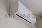
I must say that I had no complaints about the packaging. Classic yellow package + additional layer of puffy. The charger itself had no external damage.
That means it's time for a debate! During the dispute, I provided the seller with photos confirming the malfunction and offered a partial refund. As a result, 160 rubles were returned to my card. I consider this a good outcome, because. The charger also came with a Micro USB cable, the average price of which is just about 50 rubles, which is how much I lost on this deal.
I armed myself with tools (a mediator + a plastic card) and proceeded to the autopsy.
The case consists of two parts fastened with plastic latches. The gap is small. There are no burrs and irregularities. After opening, I saw the standard insides of an induction charger. Inductor and controller board.

The board was made quite neatly, no snot or flux smudges were found, but the coil was soldered to the board poorly, although there is contact in general, and the malfunction is most likely not in this. What surprised me the most was the use of the SMT8S microcontroller in this device. I always believed that special microcircuits are used for such Qi chargers, and not universal microcontrollers.
Out of curiosity, I decided to open the serviceable charger I already had. There I found a microcontroller from Texas Instruments in the same package. It's funny to realize that the Chinese are so hardcore that instead of using highly specialized microcircuits, they adapt widespread microcontrollers to their tasks. Apparently it's cheaper.
Since both devices were disassembled, I decided to take a picture where you can see the common features of the design. As far as I can tell, the circuitry differs slightly (on the left is a working charger, on the right is the hero of the review).

Subjectively, I liked the new charger less, and the point is not only that it is faulty :) If you suddenly decide to take a similar device, pay attention that the case is made of Soft Touch rubberized plastic. Otherwise, the phone will slide on the stand, which is very inconvenient. My old charger just has a rubberized case, and the new one is just slightly rough plastic.
Well, since it came to the opening, you can make some modifications that have long been suggested. We will modify a working charger.
The first is to increase the weight, because. I was tired that the stand fidgets on the table from any sneeze. The second is to do something with the LEDs, which are too bright for my liking.
The first task was solved by improvised means, which were ten kopeck coins.
We tear off some tape and lay coins on it, I got 2 rows of 3 coins each and 4 coins in height.

Then a stack of coins is carefully, but without fanaticism, wrapped in scotch tape and such a “patty” is obtained.

I solved the problem with the brightness of the LEDs using electrical tape, a classic approach :)
The result is in front of you, the coins are fixed on double-sided tape, the electrical tape is glued to the top of the device right above the place where the LEDs are located. Glued in two layers to achieve optimal brightness.


In short, you can take such chargers, there is a risk of getting a faulty copy, but the workmanship is at a decent level, especially considering the price. After refinement, the device, due to the increased weight, does not roll on the table, and the LEDs do not burn out the eyes :)
I hope you enjoyed my review. If you have any questions, I will answer in the comments.
I plan to buy +2 Add to favorites Liked the review +13 +22Once in childhood, for my father, I assembled a primitive pulse charger with capacitor decoupling in the primary circuit of the transformer (4 microfarads x 400 V). It was called pulsed because the charge was carried out by a modified semi-sine wave, while due to the capacitor and an additional light bulb (resistor), a discharge occurred in the “non-working” half-cycle with a power of 0.1 from the charging current. Batteries with this rectifier served for 5 years (for the Soviet era - a decent period).
This year, when a charger was needed, it turned out that it had fallen into disrepair - the contacts had rusted, and began to "punch" into the case. Due to the fact that the ardor of amateur radio has diminished over the years, I decided to buy an impulse switch - an automatic machine so that there would be less trouble - by the principle it turned on (when necessary), turned off (when the charge stopped), and forgot until the next need. The choice of pulse chargers is quite large, but it seems that Chinese friends have successfully finalized Danish or Italian radio circuits, as a result of which modern devices differ from each other only in build quality. Many manuals replicate complete nonsense: "... the device automatically cleans the terminals from sulfates ..." - apparently this nonsense is reprinted by people who do not know the difference between the terminals and the anode of the battery, where sulfation occurs (Pb2SO4 + H2SO4 + O, equally 2PbSO4+H2O). This process, which intensifies during the discharge, causes the destruction of the electrode, and the impulse charge seems to remove or reduce sulfation.
So, there are no fundamental differences between impulse chargers - automatic machines (everyone writes about seven- or nine-stage charging, in my opinion this is a pure publicity stunt, all the more there is an opportunity for a further flight of thought, such as a twenty-stage, thirty-stage , etc.), so based on the battery power, you need to choose something cheaper. In my case, this is a device with a ridiculous name for the Aggressor charger (AGR / SBC-080 Brick) at a price of 02.2016. 2750 rubles with a desulfation function and a charge current of up to 8A, designed to charge batteries up to 160 Ah.

The device looks good outwardly - good thick (but terribly smelly) plastic, because of the well-fitted rubber gasket, there are no complaints about the seams, the device is intuitive, but there is one "BUT" - there is no voltage and current indication. In some cases, a “winter” charge with a current of 8A independently jumps to a charge of 2A (motorcycle battery), while the LEDs show the charge, and the additionally connected ammeter indicates its absence. Chargers with indication of current and voltage are much more expensive - within $ 200, meanwhile, a simple refinement of any, I emphasize, any charger using an ampervoltmeter, for example, for 250 - 300 rubles, will turn your device into a more attractive and convenient equipment in use.
The ampervoltmeter can be placed either in the charger itself (if there is room for it), or outside it - in a special box, connecting it to the wires going to the battery for charging. To select a place, we will carry out an audit of the charger, for which we wring out the side plastic pads and unscrew 6 screws. Having removed the cover, it is clear that the ammeter voltmeter cannot be placed on the front panel - otherwise the board will have to be changed. To output the ammeter to the rear panel, there are several places, I chose closer to the charging cables.


Approximate location of the ammeter. Having cut the case of the ampervoltmeter with a little wire cutters, I positioned the device as conveniently as possible inside the case (slightly to the left of the center line), after which I carefully turned the charger over, keeping the place where the ampervoltmeter would be installed in the charger case and outlined the hole. Further, the matter of home technology - in 15 minutes, on the inside of the outlined rectangle, I drilled about 40 holes with a thin drill using a drill or screwdriver, combined them with the same drill and freed the window for the ammeter voltmeter. Having corrected the edges with a file, I installed an ammeter voltmeter in the window and fixed it with hot glue. The ampervoltmeter is tightly and rather firmly placed in the window, does not protrude beyond the limits of the limiter, while almost all the information on the rear has been preserved.


Next, cutting the (-) negative wire of the charger (black), solder the black wire of the ammeter to the top (the ammeter has two thick wires - red and black), and to the bottom of the wire going to the battery - the red wire of the ammeter and the black wire of the voltmeter. We solder the red and yellow wires of the voltmeter to the bare (+) positive wire of the charger (there are three wires of the voltmeter - yellow, red and black, they are thinner). We close the soldering points with heat shrink or electrical tape, and you can start charging.
By connecting the terminals (+) and (-) to the battery, you can see its voltage on the display of the ammeter voltmeter, and the charge current will appear after the device is connected to the network and the mode is selected.


There is one inconvenience - the mode switch button is located on the front side, and the ammeter is on the back, but this only begs for a rework. As you can see, the alteration did not touch the circuit diagram, but only affected the cables going to the battery being charged, and therefore an external version of the location of the ammeter in a small case is possible for this charger, as well as for any other.
Sincerely, Vadim Zakharov.
Now all cell phone manufacturers have agreed and everything that is in stores is charged via a USB connector. This is very good, because chargers have become universal. In principle, a cell phone charger is not.
This is only a pulsed DC voltage source of 5V, and the actual charger, that is, the circuit that monitors the charge of the battery and ensures its charge, is located in the cell phone itself. But, the point is not this, but the fact that these “chargers” are now sold everywhere and are already so cheap that the issue of repair disappears somehow by itself.
For example, in a store, “charging” costs from 200 rubles, and on the well-known Aliexpress there are offers from 60 rubles (including delivery).
circuit diagram
A diagram of a typical Chinese charge, copied from the board, is shown in fig. 1. There may also be a variant with the rearrangement of the diodes VD1, VD3 and the zener diode VD4 to a negative circuit - Fig. 2.
And more "advanced" options may have rectifier bridges at the input and output. There may be differences in part numbers. By the way, the numbering on the diagrams is given arbitrarily. But this does not change the essence of the matter.
Rice. 1. A typical diagram of a Chinese network charger for a cell phone.
Despite the simplicity, this is still a good switching power supply, and even a stabilized one, which is quite suitable for powering something other than a cell phone charger.

Rice. 2. Scheme of a network charger for a cell phone with a changed position of the diode and zener diode.
The circuit is based on a high-voltage blocking oscillator, the generation pulse width of which is controlled by an optocoupler, the LED of which receives voltage from a secondary rectifier. The optocoupler lowers the bias voltage based on the key transistor VT1, which is set by resistors R1 and R2.
The load of the transistor VT1 is the primary winding of the transformer T1. Secondary, lowering, is winding 2, from which the output voltage is removed. There is also winding 3, it also serves to create positive feedback for generation, and as a source of negative voltage, which is made on the diode VD2 and capacitor C3.
This negative voltage source is needed to reduce the voltage at the base of the transistor VT1 when the optocoupler U1 opens. The stabilization element that determines the output voltage is the Zener diode VD4.
Its stabilization voltage is such that, in combination with the direct voltage of the IR LED of the optocoupler U1, it gives exactly the necessary 5V that is required. As soon as the voltage on C4 exceeds 5V, the VD4 zener diode opens and current flows through it to the optocoupler LED.
And so, the operation of the device does not raise questions. But what if I need not 5V, but, for example, 9V or even 12V? This question arose along with the desire to organize a network power supply for a multimeter. As you know, popular in amateur radio circles, multimeters are powered by Krona, a compact 9V battery.
And in "field" conditions, this is quite convenient, but in home or laboratory I would like to be powered from the mains. According to the scheme, “charging” from a cell phone is in principle suitable, it has a transformer, and the secondary circuit does not come into contact with the mains. The problem is only in the supply voltage - "charging" gives out 5V, and the multimeter needs 9V.
In fact, the problem with increasing the output voltage is solved very simply. It is only necessary to replace the VD4 zener diode. To get a voltage suitable for powering a multimeter, you need to put a zener diode on a standard voltage of 7.5V or 8.2V. In this case, the output voltage will be, in the first case, about 8.6V, and in the second about 9.3V, which, both, is quite suitable for a multimeter. A zener diode, for example, 1N4737 (this is 7.5V) or 1N4738 (this is 8.2V).
However, another low-power zener diode for this voltage is also possible.
Tests have shown that the multimeter performs well when powered by this power supply. In addition, an old pocket radio powered by Krona was also tried, it worked, only interference from the power supply slightly interfered. The voltage in 9V is not limited at all.

Rice. 3. Voltage adjustment unit for reworking a Chinese charger.
Do you want 12V? - No problem! We put the zener diode on 11V, for example, 1N4741. Only you need to replace the capacitor C4 with a higher voltage one, at least 16V. You can get even more stress. If you remove the zener diode at all, there will be a constant voltage of about 20V, but it will not be stabilized.
It is even possible to make a regulated power supply by replacing the zener diode with a regulated zener diode such as the TL431 (Figure 3). The output voltage can be adjusted, in this case, by a variable resistor R4.
Karavkin V. RK-2017-05.
The number of mobile communication devices in active use is constantly growing. Each of them comes with a charger supplied in the kit. However, not all products meet the deadlines set by manufacturers. The main reasons are the low quality of electrical networks and the devices themselves. They often break and it is not always possible to quickly obtain a replacement. In such cases, a phone charger circuit is required, using which it is quite possible to repair a faulty device or make a new one with your own hands.
The main malfunctions of chargers
The charger is considered the weakest link that mobile phones are equipped with. They often fail due to low-quality parts, unstable mains voltage, or as a result of ordinary mechanical damage.
The simplest and best option is to purchase a new device. Despite the difference in manufacturers, the general schemes are very similar to each other. At its core, this is a standard blocking generator that rectifies the current using a transformer. Chargers may differ in connector configuration, they may have different mains input rectifier circuits, made in a bridge or half-wave version. There are differences in the little things that are not decisive.
As practice shows, the main malfunctions of the memory are the following:
- Breakdown of the capacitor installed behind the mains rectifier. As a result of the breakdown, not only the rectifier itself is damaged, but also a low-resistance fixed resistor, which simply burns out. In such situations, the resistor practically acts as a fuse.
- Transistor failure. As a rule, many circuits use high-voltage high-power elements marked 13001 or 13003. For repairs, you can use the domestic product KT940A.
- Generation does not start due to a breakdown of the capacitor. The output voltage becomes unstable when the zener diode is damaged.
Almost all charger cases are non-separable. Therefore, in many cases, repair becomes impractical and inefficient. It is much easier to use a ready-made DC source by connecting it to the desired cable and supplementing it with the missing elements.
Simple electronic circuit
The basis of many modern chargers are the simplest switching circuits of blocking generators, containing only one high-voltage transistor. They are compact in size and capable of delivering the required power. These devices are completely safe to use, since any malfunction leads to a complete absence of voltage at the output. Thus, high unstabilized voltage is excluded from entering the load.

Rectification of the alternating voltage of the network is carried out by the diode VD1. Some circuits include a whole diode bridge of 4 elements. The current pulse is limited at the moment of switching on by the resistor R1, with a power of 0.25 W. In the event of an overload, it simply burns out, protecting the entire circuit from failure.
To assemble the converter, a conventional flyback circuit based on the transistor VT1 is used. More stable operation is provided by the resistor R2, which starts generation at the moment of power supply. Additional generation support occurs due to the capacitor C1. Resistor R3 limits the base current during overloads and surges in the network.
Enhanced Reliability Scheme
In this case, the input voltage is rectified by using a diode bridge VD1, capacitor C1 and a resistor with a power of at least 0.5 W. Otherwise, during the charging of the capacitor when the device is turned on, it may burn out.
Capacitor C1 must have a capacity in microfarads equal to the power of the entire charger in watts. The basic circuit of the converter is the same as in the previous version, with the transistor VT1. To limit the current, an emitter with a current sensor based on resistor R4, diode VD3 and transistor VT2 is used.

This phone charger circuit is not much more complicated than the previous one, but much more efficient. The inverter can work stably without any limitation despite short circuits and loads. Transistor VT1 is protected from self-induction EMF emissions by a special circuit consisting of elements VD4, C5, R6.
It is necessary to install only a high-frequency diode, otherwise the circuit will not work at all. This chain can be installed in any similar schemes. Due to it, the body of the key transistor heats up much less, and the service life of the entire converter is significantly increased.
The output voltage is stabilized by a special element - the Zener diode DA1, installed at the charging output. Optocoupler V01 is used for.
Do-it-yourself charger repair
With some knowledge of electrical engineering and practical skills in working with tools, you can try to repair a cell phone charger on your own.
First of all, you need to open the case of the charger. If it is collapsible, you will need an appropriate screwdriver. With a non-separable option, you will have to act with sharp objects, dividing the charge along the junction line of the halves. As a rule, a non-separable design indicates a low quality of chargers.

After disassembly, a visual inspection of the board is carried out in order to detect defects. Most often, faulty places are marked by traces of burning resistors, and the board itself at these points will be darker. Mechanical damage is indicated by cracks on the case and even on the board itself, as well as bent contacts. It is quite enough to bend them into place towards the board in order to resume the supply of mains voltage.
Often the cord at the output of the device is broken. Breaks occur most often near the base or directly at the plug. The defect is detected by measuring the resistance.
If there are no visible damages, the transistor is soldered and called. Instead of a faulty element, parts from burned-out energy-saving lamps will do. Everyone else did - resistors, diodes and capacitors - are checked in the same way and, if necessary, changed to serviceable ones.
The author offers options for converting a cell phone charger into a stabilized power supply with adjustable output voltage or into a stable current source, for example, for charging batteries.
One of the most numerous electronic devices that are widely used in everyday life is undoubtedly chargers (chargers) for cell phones. Some of them can be improved by improving the parameters or expanding the functionality. For example, turn the charger into a stabilized power supply (PSU) with an adjustable output voltage or a charger with a stable output current.
This will allow you to power various radio equipment from the mains or charge Li-Ion, Ni-Cd, Ni-MH batteries and batteries.
A significant part of the memory for cell phones is assembled on the basis of a single-transistor self-generator voltage converter. One of the options for such a memory circuit, using the ACH-4E model as an example, is shown in fig. 1. It also shows how to turn it into a PSU with adjustable output voltage. Designations of regular elements are given in accordance with the marking on the printed circuit board.
Rice. 1. One of the variants of the memory circuit on the example of the ACH-4E model
Newly introduced elements and improvements are highlighted in color.
In simple memory devices, to which the final one belongs, a half-wave rectifier of the mains voltage is often used, although on the board, in most cases, there is a place to place a diode bridge. Therefore, at the first stage of refinement, the missing diodes were installed, and the resistor R1 was removed from the board (it was installed in place of the diode D4) and soldered directly to one of the pins of the XP1 plug. It should be noted that there are memory devices in which there is also no smoothing capacitor C1. If so, it is necessary to install a capacitor with a capacity of 2.2 ... 4.7 microfarads for a rated voltage of at least 400 V. Then the capacitor C5 is replaced with another one with a larger capacity. In this version, the modifications of the memory are shown in Fig. 2.

Rice. 2. Modified memory
In the original charger, a 1N4937 diode was used in the output rectifier, which was replaced by a 1N5818 Schottky diode, which made it possible to increase the output voltage. After such refinement, the dependences of the output voltage on the load current were removed, which are shown in blue in Fig. 3. The amplitude of the output voltage ripple increases from 50 to 300 mV with increasing load current. At a load current of more than 300 mA, ripples with a frequency of 100 Hz appear.

Rice. 3. Dependences of the output voltage on the load current
The dependences show that the stability of the output voltage in the memory is low. This is due to the fact that its stabilization is carried out indirectly by controlling the voltage on the winding II, namely, by rectifying the pulses on the winding II and supplying the closing voltage through the zener diode ZD (stabilization voltage 5.6 ... 6.2 V) to the base of the transistor Q1 .
To increase the stability of the output voltage and the possibility of its adjustment, the DA1 microcircuit (parallel voltage stabilizer) was introduced at the second stage of refinement. Converter control and galvanic isolation are implemented using a transistor optocoupler U1. To suppress impulse noise with the frequency of the self-oscillator, an L1C6C8 filter is additionally installed. Resistor R9 removed.
The output voltage is set by a variable resistor R12. When the voltage at the control input of the DA1 microcircuit (pin1) exceeds 2.5 V, the current through the microcircuit and, accordingly, through the emitting diode of the optocoupler U1 will increase sharply. The phototransistor of the optocoupler will open, and the closing voltage from capacitor C4 will be applied to the gate of the base of transistor Q1. This will lead to the fact that the duty cycle of the oscillator pulses will decrease (or generation will fail). The output voltage will stop growing and begin to gradually decrease due to the discharge of capacitors C5 and C8.
When the voltage at the control input of the microcircuit becomes less than 2.5 V, the current through it will decrease and the phototransistor will close. The duty cycle of the oscillator pulses will increase (or it will start working), and the output voltage will increase. The output voltage interval, which can be set by resistor R12, is 3.3 ... 6 V. Voltages less than 3.3 V, taking into account the drop on the emitting diode of the optocoupler, are not enough for the normal operation of the microcircuit. The dependences of the output voltage (for different values) on the load current of the modified device are shown in red in Fig. 3. Amplitude of output voltage ripple - 20...40 mV.
The elements (except for the variable resistor) of the second stage of refinement are placed on a single-sided printed circuit board made of foil fiberglass with a thickness of 0.5 ... 1 mm, its drawing is shown in fig. 4. Mounting - from the printed conductors. You can use fixed resistors MLT, C2-23, P1-4, capacitors C6, C7 - ceramic, C5 - oxide imported, it is removed from the motherboard of a personal computer, C8 - oxide low-profile imported. Since the output voltage has to be set infrequently, not a variable resistor was used, but a trimmer PVC6A (POC6AP). This made it possible to install it on the back wall of the memory case. Inductor L1 is wound in one layer with PEV-2 0.4 wire on a cylindrical ferrite magnetic circuit with a diameter of 5 mm and a length of 20 mm (from the SMPS inductor of the computer). You can use optocouplers of the PC817 series and the like. The board with the parts (Fig. 5) is inserted into the free space of the memory (partially above the capacitor C1), the connections are made with pieces of insulated wire. For a tuning resistor in the rear wall of the memory, a hole of the appropriate size is made into which it is glued. After checking the device, the resistor R12 is provided with a scale (Fig. 6).

Rice. 4. Printed circuit board and elements on it

Rice. 5. Board with details

Rice. 6. Scale on memory
The second option for finalizing the memory is the introduction of a current stabilizer (or limiter) into it. This will charge Li-Ion or Ni-Cd, Ni-MH batteries and batteries containing up to four batteries. The scheme of such refinement is shown in Fig. 7. Using the switch, you can select the operating modes: power supply or one of the two "memory" modes with current limitation. The 220 uF capacitor (C5) was replaced by a 470 uF capacitor, but with a higher voltage, since in the “ZU” modes without load, the output voltage can increase to 6 ... 8 V.

Rice. 7. Scheme of the second option for finalizing the memory
In the "BP" mode, the device operates normally. When switching to one of the "memory" modes, the output current flows through the resistor R10 (or R11). When the voltage on it reaches 1 V, part of the current will begin to branch into the emitting diode of the optocoupler U1, which will lead to the opening of the phototransistor. This will lead to a decrease in the output voltage and stabilization (limitation) of the output current I out. Its value can be determined by approximate formulas: I out \u003d 1 / R10 or I out \u003d 1 / R11. A selection of these resistors set the desired current value. The field-effect transistor VT1 limits the current through the emitting diode of the optocoupler and thereby protects it from failure.
Most of the parts are placed on a single-sided printed circuit board (Fig. 8 and Fig. 9) made of foil fiberglass with a thickness of 0.5 ... 1 mm. The field effect transistor must be with an initial drain current of at least 25 mA. The switch is any small-sized slide switch in one or two directions and three positions, for example SK23D29G, it is placed on the rear wall of the memory and provided with a scale. If you apply the switch to a larger number of positions, you can increase the number of nominal current values and thereby expand the range of rechargeable batteries.

Rice. 8. Printable board and elements on it

Since charging is carried out with a stable current, it should be carried out for a certain time, which depends on the type and capacity of the rechargeable battery or battery.
Publication date:
11.12.2017Readers' opinions
- Alius / 22.07.2019 - 07:06
1. Is it possible to raise the output voltage to 12-15 volts with a simple modification (setting a zener diode to 12-15V, or TL431 ...)? 2. The zener diode must be removed from the circuit (Fig. 1, Fig. 7) with the described refinement ...? (It's just not clear on the diagram ...) 3. Thank you for your answer in advance; and the author! - anatoliy / 23.12.2017 - 19:22
very useful information. A detailed description of the ongoing improvement is given, understandable to any "teapot". Thank you.