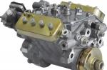
BMW S63 engine- 8-cylinder direct injection (TVDI) power unit developed by BMW Motorsport as a replacement for the 10-cylinder.
The BMW S63 engine was developed from and debuted in 2009 on the X6M. Compared to the N63 engine, the pistons, camshafts, cooling system, and supercharging system have been replaced on the S63. This was made possible thanks to some changes, primarily the location of the catalysts, which are placed together with two turbochargers above the formed two rows of cylinders - V.
This power unit was installed under the hood, and.
BMW S63B44 engine
S63B44O0- the first 555-horsepower version of the power unit installed on and.
S63B44T0 The second, updated variant debuted on the sedan and features more power as it is enhanced with even more innovative technologies such as Valvetronic and a completely redesigned cooling system.
S63 Top is also installed on:

 The structure of the cross exhaust manifold in S63
Specifications of the BMW S63 engine
| S63B44O0 | S63B44T0 (S63 Top) | |
| Volume, cm³ | 4395 | 4395 |
| The order of operation of the cylinders | 1-5-4-8-6-3-7-2 | 1-5-4-8-6-3-7-2 |
| Cylinder diameter / piston stroke, mm | 89,0/88,3 | 89,0/88,3 |
| Power, hp (kW)/rpm | 555 (408)/6000 | 560 (412)/6000-7000 |
| Torque, Nm/rpm | 680/1500-5650 | 680/1500-5750 |
| Compression ratio, :1 | 9,3 | 10,0 |
| Liter power, hp (kW)/liter | 126,2 (92,8) | 127,4 (93,7) |
| Fuel consumption, l/100 km | 13,9 | 9,9 |
| Maximum allowable rpm | 6800 | 7200 |
| CO2 emissions, g/km | 325 | 232 |
| Control system | MSD85.1 | MEVD17.2.8 |
| Engine weight, ∼ kg | 162 | 172 |
| Exhaust gas compliance | EURO 5 | EURO 5 |
| ∅ plate / inlet valve stem, mm | 33,2/6 | 33,2/6 |
| ∅ plate / exhaust valve stem, mm | 29/6 | 29/6 |
| Max. intake/exhaust valve stroke, mm | 8,8/9,0 | 8,8/9,0 |
| Inlet side VANOS adjustment range, °KV | 50 | 70 |
| Adjustment range VANOS exhaust side, ° KV | 50 | 55 |
| Inlet camshaft position change angle, °KV | 70-120 | 55-125 |
| Exhaust camshaft position change angle, °KV | 73,5-123,5 | 60-115 |
| The duration of the opening of the intake camshaft, ° KV | 231 | 260 |
| Exhaust camshaft opening time, °KV | 252 | 252 |
BMW S63TU engine
In 2014, an upgraded S63TU was introduced in Los Angeles ( S63B44B). This motor marked its debut on new sports crossovers and.
BMW S63 TU engine parameters
Engine BMW S63 TU (M5)
This version of the motor was presented. The engine received new turbochargers, an optimized lubrication and cooling system, an improved and lightweight exhaust system.
Engine parameters BMW S63 TU (M5)
BMW S63 engine problems
When operating the motor within reasonable limits, it will show itself from a very good side. Its main problem can be considered excessive oil consumption and possible problems with cylinders at high loads. Most of all, this applies to the first version of the S63B44A (555-horsepower), since BMW engineers, when developing an updated version of the S63B44T0, worked to eliminate this problem.
The S63 TOP engine was first used in the F10M. The S63 TOP engine is a modification based on the S63 engine. The SAP designation is S63B44T0.
- In this case, the designation "S" indicates the development of the engine by M GmbH.
- Number 63 indicates the type of V8 engine.
- "B" stands for gasoline engine and fuel - gasoline.
- Number 44 indicates the engine displacement at 4395 cm3.
- T0 stands for technical revision of the base engine.
The upgrade was aimed at improving performance for use in the new M5 and M6 while reducing fuel consumption. This was achieved through sequential throttling as well as the use of Turbo-VALVETRONIC Direct Injection (TVDI) technology. It is already known and used in the N20 and N55 engines.
The following figure shows the installation position of the S63 TOP engine in the F10M.
The newly developed S63 TOP engine is characterized by the following parameters:
- V8 Twin Turbo Twin-Scroll-Valvetronic (TVDI) direct injection petrol engine with 412 kW (560 hp)
- Torque 680 Nm from 1500 rpm
- Liter power 93.7 kW
Specifications
| Design | V8 Direct Injection Turbo-VALVETRONIC (TVDI) |
| The order of operation of the cylinders | 1-5-4-8-6-3-7-2 |
| Regulator-limited speed | 7200 rpm |
| Compression ratio | 10,0: 1 |
| Supercharging | 2 exhaust turbochargers with twin-scroll technology |
| Max boost pressure | up to 0.9 bar |
| Valves per cylinder | 4 |
| Fuel calculation | 98 ROZ (Research Octane Number) |
| Fuel | 95 - 98 ROZ (Research Octane Number) |
| fuel consumption. | 9.9 l/100 km |
| Exhaust gas toxicity standard for European countries | EURO 5 |
| emission of harmful substances | 232 g CO2 / km |
Full load diagram S63B44T0
Brief description of the node
In this description of operation, the differences from known S63 engines are mainly described.
The following components have been redesigned for the S63 TOP engine:
- Valve drive
- cylinder head
- exhaust turbocharger
- Catalyst
- injection system
- Belt drive
- vacuum system
- Sectional oil sump
- Oil pump
Digital Engine Electronics (DME)
The new S63 TOP engine uses the digital engine electronics (DME) MEVD17.2.8, which includes a master and an actuator.
Activation of the Digital Engine Electronics (DME) is carried out by the Car Access System (CAS) via the activation wire (terminal 15, activation). Sensors installed on the engine and in the vehicle transmit input signals. On the basis of input signals and setpoints calculated by a special mathematical model, as well as the characteristic fields stored in the memory, signals are calculated to activate the actuators. The DME controls the actuators directly or through relays.
After terminal 15 is switched off, the post-on phase starts. During the post-power-up phase, the correction values are determined. The DME master control unit indicates that it is ready to enter standby mode via a bus signal. After all the computers involved in the process have indicated that they are ready to go into standby mode, the central gateway module (ZGM) transmits a signal via the bus and approx. communication with the ECU is interrupted after 5 seconds.
The following figure shows the mounting position of the Digital Engine Electronics (DME).
The Digital Engine Electronics (DME) is a user of the FlexRay bus, PT-CAN, PT-CAN2 and LIN bus. The Digital Engine Electronics (DME) is connected, among other things, via a LIN bus on the vehicle side to the intelligent battery sensor. For example, on the engine side, a generator and an additional electric water pump are connected to the LIN bus. The Digital Engine Electronics (DME) in the S63 TOP engine is connected to the oil condition sensor via a binary serial data interface. Power for the Digital Engine Electronics (DME) and Digital Engine Electronics 2 (DME2) is supplied via the built-in supply module via terminal 30B. Terminal 30B is activated by the Car Access System (CAS). A second additional electric water pump is connected to the LIN bus of the Digital Engine Electronics 2 (DME2) in the S63 TOP engine.
The digital engine electronics (DME) board additionally contains a temperature sensor and an ambient pressure sensor. The temperature sensor is intended for thermal monitoring of components in the DME control unit. Ambient pressure is necessary for diagnostics and verification of the reliability of the sensor signals.
Both control units are cooled in the charge air cooling circuit by means of coolant.
The following figure shows the cooling circuit for cooling the Digital Engine Electronics (DME) as well as the charge air coolers.
| Designation | Explanation | Designation | Explanation |
|---|---|---|---|
| 1 | Air cooler | 2 | Additional electric water pump of the 1st row of cylinders |
| 3 | Charge air cooler 1st row of cylinders | 4 | |
| 5 | 6 | Charge air cooler 2nd row of cylinders | |
| 7 | Additional electric water pump of the 2nd row of cylinders |
To ensure cooling of the Digital Engine Electronics (DME), it is important to connect the coolant hoses correctly without kinks.
cylinder head cover
Due to changes in the crankcase ventilation system, it was necessary to redesign the cylinder head cover.
A labyrinth separator integrated in the cylinder head cover is used to separate the oil contained in the leaking gas. In the direction of flow, there is a pre-separator and a fine filter plate with small nozzles. A baffle plate with non-woven fabric at the front further separates the oil particles. The oil return is equipped with a check valve to prevent the direct suction of leaking gases without separation. The cleaned escaping gases are fed into the intake system, depending on the operating condition, either through a non-return valve or through a volume control valve. An additional line from the crankcase ventilation system to the intake system is not required, since the appropriate openings for the individual intake ports are integrated into the cylinder head. Each row of cylinders has its own crankcase ventilation system.
New is the location of the camshaft position sensors of the cylinder head cover. A camshaft position sensor for the intake camshaft and exhaust camshaft is integrated, respectively, for each cylinder bank.
crankcase ventilation system
When operating a naturally aspirated engine, there is a vacuum in the intake system. Due to it, the volume control valve is opened, and the purified leaking gases through the holes in the cylinder head enter the intake channels and, as a result, the intake system. Since there is a risk that oil will be sucked in through the crankcase ventilation system in case of strong vacuum, the volume control valve performs the function of throttling. The volume control valve restricts the flow and thus the pressure level in the crankcase.
The vacuum in the crankcase ventilation system keeps the check valve in the closed position. Additional outside air enters the oil separator through a leak hole located above it. The vacuum in the crankcase ventilation system is thus limited to a maximum of 100 mbar.
In boost mode, the pressure in the intake system rises and thereby closes the volume control valve. In this operating state, a vacuum exists in the purified air pipeline. If the non-return valve is opened to the purified air line, the purified leak gases are directed to the intake system.
The following figure shows the installation position of the crankcase ventilation system.
| Designation | Explanation | Designation | Explanation |
|---|---|---|---|
| 1 | Oil separator | 2 | Non-return valve to the purified air pipeline with a hole for leakage |
| 3 | Wire to the purified air pipeline | 4 | Baffle baffle with non-woven baffle in front |
| 5 | Fine filter plate with small nozzles | 6 | Pre-separator |
| 7 | Inlet of permeable gases | 8 | Oil return line |
| 9 | Oil return with check valve | 10 | Connecting line with inlet |
| 11 | Volume control valve for intake system with throttling function |
Valve drive
The S63 TOP engine also features fully variable valve travel in addition to dual VANOS. The valve actuator itself consists of known components. The new components are the rocker arm and intermediate arm made of molded sheet metal. In combination with a lightweight camshaft, the weight has been further reduced. To drive the camshafts of each row of cylinders, a toothed sleeve chain is used. The chain tensioners, tensioning bars and damper bars are the same for both cylinder banks. Oil jets are built into the chain tensioners.
Valvetronic
Valvetronic consists of a variable valve stroke system and a variable valve timing system with a variable opening phase of the intake valves, with the closing moment of the intake valve being chosen arbitrarily. The valve travel is controlled only on the intake side, while the valve timing is controlled on both the intake and exhaust sides. The opening moment and the closing moment, and therefore the duration of the opening, as well as the stroke of the inlet valve, are freely selectable.
The 3rd generation Valvetronic is already used in the N55 engine.
Valve Stroke Adjustment
As shown in the following figure, the Valvetronic servomotor is located on the intake side of the cylinder head. The eccentric shaft sensor is built into the Valvetronic servomotor.
| Designation | Explanation | Designation | Explanation |
|---|---|---|---|
| 1 | Exhaust camshaft | 2 | intake camshaft |
| 3 | backstage | 4 | Intermediate lever |
| 5 | Spring | 6 | Valvetronic servomotor |
| 7 | Valve spring on intake side | 8 | VANOS on the intake side |
| 9 | Inlet valve | 10 | Exhaust valve |
| 11 | Valve spring on exhaust side | 12 | VANOS on the exhaust side |
VANOS
There are the following differences between the S63 engine and the S63 TOP engine:
- The adjustment range of the VANOS system has been extended by reducing the number of vanes from 5 to 4. (70° intake crankshaft, 55° exhaust crankshaft)
- By using aluminum instead of steel, the weight has been reduced from 1050g to 650g.
cylinder head
The cylinder head of the S63 TOP engine is a new development with integrated air ducts for the crankcase ventilation system. The oil circuit has also been redesigned and adapted to the increased output. The S63 TOP engine, like the N55 engine before, uses the 3rd generation Valvetronic system.
The cylinder head gasket uses a new three-layer spring steel seal. The contact surfaces on the side of the cylinder head and cylinder block are provided with a non-stick coating.
The following figure shows the components integrated in the cylinder head.
Differentiated intake system
The intake system has been modified to match the installation position in the F10, while also receiving a flow-optimized connection to the throttle body. Unlike the S63 engine, the S63 TOP engine does not have a charge air recirculation valve. The S63 TOP engine has its own intake silencer for each cylinder bank. A hot-film air mass meter is respectively integrated into the intake silencer. An innovation is the use of a 7th generation hot film air mass meter. The hot film air mass meter is the same as in the N20 engine.
The heat exchangers for air and coolant have also been adapted to increase the cooling intensity.
The following figure shows the walkthrough of the respective components.
| Designation | Explanation | Designation | Explanation |
|---|---|---|---|
| 1 | charge air cooler | 2 | exhaust turbocharger |
| 3 | Connecting the crankcase ventilation system to the purified air pipeline | 4 | Charge air temperature sensor and intake manifold pressure sensor |
| 5 | intake system | 6 | throttle valve |
| 7 | Hot Film Air Mass Meter | 8 | Suction muffler |
| 9 | suction pipe | 10 | boost pressure sensor |
exhaust turbocharger
The S63 TOP engine has 2 exhaust turbochargers with twin-scroll technology. Turbine wheels and compressor wheels have also been redesigned. Thanks to the modernization of the turbine wheels, the performance and efficiency at high speeds of the exhaust turbocharger have been improved. This change makes the exhaust turbocharger less sensitive to the operation of the pumps. Therefore, it was possible to abandon the charge air recirculation valve. The exhaust gas turbocharger is of the already known design with a vacuum controlled bypass valve.
The following graphic shows the exhaust manifold and exhaust turbocharger with Twin-Scroll for all cylinder banks.
Catalyst
The S63 TOP engine has a double-wall catalytic converter per cylinder bank. Catalysts no longer have tripping elements.
Known lambda probes manufactured by Bosch are used. The control probe is located in front of the catalyst, as close as possible to the turbine outlet. Its position was chosen in such a way that it was possible to process the data of all cylinders separately. The control probe is located between the first and second ceramic monoliths.
The following figure shows a catalyst tube with built-in components.
Exhaust system
The exhaust system has been adapted to the S63 TOP engine and to the specific vehicle. The exhaust manifold for all rows of cylinders has been reinforced, now it is made in the form of a pipe elbow. Exhaust manifold outer shells are no longer required. To compensate for thermomechanical movements inside the exhaust manifolds, release elements are welded into the exhaust manifolds. The dual-flow exhaust system leads to the rear of the vehicle and ends with 4 round exhaust pipes. The S63 TOP engine has active muffler flaps that are activated by vacuum.
The following figure shows the exhaust system starting from the catalyst pipe.
Additional electric coolant pump
An additional electric water pump, together with a coolant pump, is connected to the main cooling circuit. An additional electric water pump is responsible for cooling the exhaust turbocharger. The optional electric water pump operates on the principle of a centrifugal pump and is designed to supply coolant.
The DME activates an additional electric water pump via the control wire, depending on the need.
The optional electric water pump can operate from 9 to 16 volts, with a nominal voltage of 12 volts. The temperature range for the coolant is -40°C to 135°C.
injection system
The S63 TOP engine uses high pressure injection already known from the N55 engine. It differs from jet direct injection by the use of solenoid injectors with multi jet spray. The HDEV 5.2 solenoid injector from Bosch, unlike the outward-opening injection system, is an inward-opening multi-jet valve. The HDEV 5.2 solenoid nozzle is characterized by high variability in terms of angle of incidence and jet shape and is designed for system pressures up to 200 bar.
The next difference is the welded line. The individual hose lines for fuel injection are no longer screwed to the line, but welded to it.
In the S63 TOP engine, it was decided to abandon the low fuel pressure sensor. The known adjustment of the amount of fuel is used by registering the value of the engine speed and load.
The high pressure pump is already known from 4-, 8- and 12-cylinder engines. To ensure sufficient fuel supply pressure at any load level, the S63 TOP engine uses one high-pressure pump for each cylinder bank. The high pressure pump is bolted to the cylinder head and is driven by the exhaust camshaft.
The following figure shows the location of the injection system components.
Belt drive
The belt drive has been adapted to the increased engine speed. The belt pulley on the crankshaft has a smaller diameter. Accordingly, the drive belts were changed.
The belt drive drives the main belt drive with alternator, coolant pump and power steering pump. The main belt drive is tensioned by means of a mechanical tension roller.
An additional belt drive covers the air conditioning compressor and is equipped with elastic belts.
The following figure shows the components connected to the belt drive.
vacuum system
The vacuum system of the S63 TOP engine has some changes compared to the S63 engine.
The vacuum pump has a two-stage design so that the brake booster receives most of the vacuum created. The vacuum reservoir is no longer located in the space in the camshaft, but is installed on the underside of the oil sump. The vacuum lines have been adapted accordingly.
The following figure shows the components of the vacuum system and their installation position.
Sectional oil sump
The oil sump is made of aluminum and has a two-section design. The oil filter is built into the top of the oil sump and is accessible from below. The oil pump is bolted to the top of the oil sump and is chain driven from the crankshaft. To prevent foaming of the engine oil, the drive chain and chain sprocket are separated from the oil. The oil damper is integrated into the upper part of the oil sump. The oil drain plug in the oil filter cap is no longer required.
The following figure shows a sectional oil sump. For a better schematic representation of the components, the figure is rotated 180°.
Oil pump
The S63 TOP engine has a volume flow controlled oil pump with suction and discharge stage in one housing. The oil pump is firmly screwed to the top of the oil sump.
The oil pump is driven by the crankshaft bush chain. The bush chain is held in tension by the tensioner bar.
The suction stage uses a pump that, using an additional suction line, supplies engine oil from the front of the oil sump to the rear.
To provide oil pressure to the engine, a vane pump with a oscillating spool, controlled by volume flow, is used. To ensure a reliable oil supply, the suction port is located at the rear of the oil sump.
The following figure shows the oil pump components and their drive.
Piston, connecting rod and crankshaft
Due to the change in the combustion method and the increase in the speed level, these components have also been redesigned.
Piston
Cast pistons are now used with a set of Mahle piston rings. The shape of the piston head has been suitably adapted to the combustion method and the use of electromagnetic nozzles with multi-jet atomization.
connecting rod
We are talking about a broken forged connecting rod with a direct division. The small one-piece connecting rod head, as in the N20 and N55 engines, has a molded hole. Thanks to this shaped bore, the forces exerted by the piston via the piston pin are optimally distributed over the surface of the bushing. Due to the improved distribution of forces, the load on the edges is reduced.
Crankshaft
The crankshaft of the S63 TOP engine is a forged crankshaft with a hardened top layer with 6 counterweights. The crankshaft is supported by five bearings. The thrust bearing is located in the center on the third bearing bed. Lead-free bearings are used.
System overview
| Designation | Explanation | Designation | Explanation |
|---|---|---|---|
| 1 | Fuel pressure sensor | 2 | Digital Engine Electronics 2 (DME2) |
| 3 | Additional electric coolant pump 2 | 4 | electric fan |
| 5 | 6 | Input Shaft Speed Sensor | |
| 7 | air conditioning compressor | 8 | Junction Box (JBE) |
| 9 | Front power distributor | 10 | DC/DC converter |
| 11 | Rear power distributor | 12 | Battery power distributor |
| 13 | intelligent battery sensor | 14 | Temperature sensor (NVLD, USA and Korea) |
| 15 | Membrane switch (NVLD, USA and Korea) | 16 | Dual Clutch Transmission (DKG) |
| 17 | accelerator pedal module | 18 | Electric fan relay |
| 19 | Integrated Chassis Management (ICM) | 20 | muffler damper |
| 21 | Control panel on the center console | 22 | clutch switch |
| 23 | Instrument cluster (KOMBI) | 24 | Car Access System (CAS) |
| 25 | Central Gateway Module (ZGM) | 26 | Footwell Module (FRM); |
| 27 | reversing light contact switch | 28 | Dynamic Stability Control (DSC) |
| 29 | Starter | 30 | Digital Engine Electronics (DME) |
| 31 | Oil condition sensor |
System functions
The following functions are described below:- Engine cooling
- Twin Scroll
- Oil supply
Engine cooling
The design of the cooling system is similar to that in the S63 engine. For the S63 TOP engine, the cooling circuit has been redesigned to improve performance. In the S63 TOP engine, in addition to the mechanical coolant pump, there are only 4 additional electric water pumps.
- Additional electric water pump for exhaust turbocharger cooling.
- Two additional electric water pumps for cooling the aftercooler and digital engine electronics (DME).
- Additional electric water pump for heating the vehicle interior.
Engine cooling and charge air cooling have separate cooling circuits.
By changing the geometry of the impeller for the coolant belt pump, an increase in coolant flow has been achieved. In this way, the cooling of the cylinder head has been optimized. An additional electric water pump is installed to ensure that both exhaust turbochargers are cooled after the engine has been switched off. During engine operation, it is also used to support cooling of the turbocharger.
In order to ensure adequate cooling of the charge air, the air and coolant heat exchangers in the S63 TOP engine are larger than in the S63 engine. They are supplied with coolant through their own cooling system with 2 additional electric water pumps. The coolant circuit for charge air cooling and digital engine electronics (DME) includes a radiator and 2 remote coolant radiators. Heat is removed from the charge air via an air/coolant heat exchanger for each cylinder bank. This heat is removed to the outside air via the coolant heat exchanger. For this, the charge air cooling has its own cooling circuit. It is independent of the engine cooling circuit.
The cooling module itself is only available in one version. Tropicalized vehicles and in combination with top speed equipment (SA840) additionally use a remote radiator (in the wheel housing on the right).
The following figure shows the refrigeration circuit.
| Designation | Explanation | Designation | Explanation |
|---|---|---|---|
| 1 | Radiator outlet coolant temperature sensor | 2 | jellied glass |
| 3 | thermostat | 4 | coolant pump |
| 5 | exhaust turbocharger | 6 | heater heat exchanger |
| 7 | double valve | 8 | Additional electric coolant pump |
| 9 | Additional electric coolant pump | 10 | Engine coolant temperature sensor |
| 11 | Expansion tank of the cooling system | 12 | electric fan |
| 13 | Radiator |
The S63 TOP engine has a temperature control system already known from the N55 engine. The thermostatic system includes independent control of the electrical cooling components - an electric fan, a programmable thermostat and coolant pumps.
The S63 TOP engine is equipped with a traditional programmable thermostat. Thanks to the electrical heating in the programmable thermostat, it was additionally possible to realize opening even at a low coolant temperature.
Twin Scroll
Twin-scroll stands for exhaust turbocharger with dual-flow turbine housing. In the turbine housing, the exhaust gas from the 2 cylinders is respectively guided separately to the turbine. Due to this, the so-called impulse boost is used more powerfully. Individually, the exhaust flows in the turbine housing of the exhaust turbocharger are guided in a spiral (scroll) to the turbine wheel.
The exhaust gas is rarely supplied to the turbine at a constant pressure. At low engine speeds, the exhaust gas reaches the turbine in a pulsating manner. Due to the pulsation, a short-term increase in the pressure ratio across the turbine is achieved. Since the efficiency increases with increasing pressure, the boost pressure and, consequently, the engine torque also increase due to the pulsation.
To improve gas exchange in the S63 TOP engine, cylinders 1 and 6, 4 and 7, 2 and 8, and 3 and 5 were respectively connected to the exhaust pipe.
A bypass valve is used to limit the boost pressure.
Oil supply
When braking and cornering with the M5/M6, very high acceleration values can occur. The resulting centrifugal forces force most of the engine oil into the front of the oil sump. If this happens, the oscillating vane pump cannot supply oil to the engine because there will be no oil to suck. Therefore, the S63 TOP engine uses an oil pump with a suction stage and a pressure stage (rotary and vane pump with oscillating spool).
In the S63 TOP engine, the components are lubricated and cooled by oil spray nozzles. Oil spray nozzles for cooling the piston crown are known in principle. They have a built-in check valve so that they open and close only from a certain oil pressure. Each cylinder has its own oil nozzle, which, thanks to its shape, maintains the correct installation position. In addition to cooling the piston crown, it is also responsible for lubricating the piston pin.
The S63 TOP engine has a full-flow oil filter known from the N63 engine. The full-flow oil filter is screwed into the oil sump from below. A valve is built into the oil filter housing. For example, with cold viscous engine oil, the valve may open the bypass around the filter. This occurs if the pressure difference before and after the filter exceeds approx. 2.5 bar. The permissible differential pressure has been increased from 2.0 to 2.5 bar. In this way, the filter is bypassed less often and dirt particles are more reliably filtered out.
The S63 TOP engine has a remote oil cooler under the cooling module for engine oil cooling. To ensure that the engine oil heats up quickly, a thermostat is built into the oil sump. The thermostat unblocks the supply line to the oil cooler, starting from an engine oil temperature of 100 °C.
The well-known oil condition sensor is used to control the oil level. Analysis of the quality of engine oil is not performed.
Service Instructions
General instructions
Note! Let the engine cool down!
Repair work is only allowed after the engine has cooled down. Coolant temperature must not exceed 40 °C.
We reserve the right to typographical errors, semantic errors and technical changes.
The BMW S63 engine is the development of a subsidiary of the BMW concern - BMW Motorsport GmbH. It is a variation of the N63 series and was first used in the production of the BMW X6M. The main emphasis of this engine series is placed on economical fuel consumption and high technical characteristics of the unit as a whole. The cross exhaust manifold, the latest Valvetronic system and many other latest developments from BMW engineers were widely used in the S63.
Specifications
| Production | Munich Plant |
| Engine brand | S63 |
| Release years | 2009-present |
| Block material | aluminum |
| Supply system | injector |
| Type | V-shaped |
| Number of cylinders | 8 |
| Valves per cylinder | 4 |
| Piston stroke, mm | 88.3 |
| Cylinder diameter, mm | 89 |
| Compression ratio | 9.3 10 |
| Engine volume, cc | 4395 |
| Engine power, hp / rpm | 555/6000 560/6000-7000 575/6000-7000 600/6000-7000 |
| Torque, Nm/rpm | 680/1500-5650 680/1500-5750 680/1500-6000 700/1500-6000 |
| Fuel | 95-98 |
| Environmental regulations | Euro 5 Euro 6 (TU) |
| Engine weight, kg | 229 |
| Fuel consumption, l/100 km (for M5 F10) - city - track - mixed. |
14.0 7.6 9.9 |
| Oil consumption, g/1000 km | up to 1000 |
| Engine oil | 5W-30 5W-40 |
| How much oil is in the engine, l | 8.5 |
| Oil change is carried out, km | 7000-10000 |
| Operating temperature of the engine, hail. | 110-115 |
| Engine resource, thousand km - according to the plant - on practice |
- - |
| checkpoint - 6automatic transmission - M DCT - 8 automatic transmission |
ZF 6HP26S GS7D36BG ZF 8HP70 |
| Gear ratios, 6 automatic transmission | 1 - 4.17 2 - 2.34 3 - 1.52 4 - 1.14 5 - 0.87 6 - 0.69 |
| Gear ratios, M DCT | 1 - 4.806 2 - 2.593 3 - 1.701 4 - 1.277 5 - 1.000 6 - 0.844 7 - 0.671 |
| Gear ratios, 8 automatic transmission | 1 - 5.000 2 - 3.200 3 - 2.143 4 - 1.720 5 - 1.313 6 - 1.000 7 - 0.823 8 - 0.640 |
Common faults and operation
The BMW S63 engine is characterized by the following malfunctions: high oil consumption, water hammer, misfiring.
The problem of increased oil consumption is associated with coking of the piston grooves, wear of the rings. The malfunction is eliminated by overhaul with the replacement of rings. Rapid oil consumption causes corrosion of alusil, in such a situation the cylinder block is changed. Turbines are located between the cylinders - there is a high concentration of heat transfer in the collapse of the block. Turbine oil return pipes pass here, which coke, and the turbines fail. The high temperature in the collapse adversely affects the vacuum tubes, as well as the plastic tubes of the cooling system.
If failures are observed during ignition, you need to check the candles, if necessary, replace them with similar ones from the M-series. With water hammer, the reason lies in the piezo injectors, they require replacement.
In order to level problems in the process of using the power unit, it is necessary to monitor the condition of the motor and carry out regular maintenance. Worn-out components must be replaced in a timely manner to avoid serious problems.