When rolling an elastic (deformed) wheel under the influence of force factors, a tangential deformation of the tire occurs, in which the actual distance from the axis of rotation of the wheel to the supporting surface decreases. This distance is called dynamic radius r d wheels. Its value depends on a number of design and operational factors, such as tire stiffness and internal pressure in it, vehicle weight per wheel, speed, acceleration, rolling resistance, etc.
The dynamic radius decreases with increasing torque and decreasing tire pressure. Value r d slightly increases with increasing vehicle speed due to the growth of centrifugal forces. The dynamic radius of the wheel is the shoulder of the application of the pushing force. Therefore it is also called power radius.
The rolling of an elastic wheel on a solid supporting surface (for example, on an asphalt or concrete highway) is accompanied by some slippage of the wheel tread elements in the zone of its contact with the road. This is due to the difference in the lengths of the sections of the wheel and the road that come into contact. This phenomenon is called elastic slip tires, as opposed to slip(slip), when all elements of the tread are displaced relative to the supporting surface. There would be no elastic slip if these sections are absolutely equal. But this is possible only when the wheel and the road have contact in an arc. In reality, the bearing contour of the deformed wheel comes into contact with the flat surface of the undeformed road, and slippage becomes inevitable.
To account for this phenomenon, the concept is used in calculations. kinematic radius wheels ( rolling radius) r to. Thus, the calculated rolling radius r k is such a radius of the fictitious undeformed a wheel that, in the absence of slippage, has the same linear (translational) rolling speeds with a real (deformed) wheel v and angular rotation ω to. That is, the value r to characterizes conditional radius, which serves to express the calculated kinematic relationship between the speed of movement v vehicle and wheel speed ω to:
A feature of the rolling radius of the wheel is that it cannot be measured directly, but is determined only theoretically. If we rewrite the above formula as:
 , (τ
- time)
, (τ
- time)
then from the resulting expression it is clear that to determine the value r can be calculated. To do this, you need to measure the path S, passed by the wheel for n revolutions, and divide it by the angle of rotation of the wheel ( φ to = 2pn).
The amount of elastic slip increases with a simultaneous increase in the elasticity (compliance) of the tire and the rigidity of the road, or, conversely, with an increase in the rigidity of the tire and the softness of the road. On a soft dirt road, increased tire pressure increases ground deformation losses. Reducing the internal pressure in the tire allows, on soft soils, to reduce the movement of soil particles and the deformation of its layers, which leads to a decrease in rolling resistance and an increase in patency.
However, on a firm ground at low pressure, excessive tire deflection occurs with an increase in the rolling friction arm. A. A compromise solution to this problem is the use of tires with adjustable internal pressure.
In practical calculations, the wheel rolling radius is estimated by the approximate formula:
r k \u003d (0.85 ... 0.9) r 0 (here r 0 - free wheel radius).
For paved roads (wheel movement with minimal slippage) take: r k = rd.
Good day, dear readers. Today I want to answer immediately a lot of questions related to wheel sizes. Many of my readers do not understand what they mean and why they are needed at all! Today I will try to explain in a simple and understandable language what the dimensions of rubber on cars mean ...
The dimensions of the rubber wheel contain a lot of useful information, you just need to be able to read it. Without this information, you will not be able to choose the right tires for your car, they simply will not fit in size. Although now on the bodies of many brands there are special plates with recommendations, you just read them and go to the store to buy the same ones. However, there are not always such plates and you need to determine the dimensions of the tires yourself! A small clarification, I will only talk about overall dimensions, there have already been many articles about other characteristics, links will definitely be below.
I will talk about them using the example of my winter wheels, KAMA EURO 519, it should be noted that they are in no way inferior to their foreign counterparts. Read informative.
To begin with, the overall dimensions
I have a wheel size R16 205/55 , these are the so-called overall dimensions. Rubber is considered low profile (more).

The notorious letter R
Many mistakenly think (to be honest, I thought so too) that the first English letter R means the abbreviation "RADIUS"! But it's not! The letter R means radial tire, read the article -. This is such a method of assembling rubber and metal cord during production. Of course, you can also meet the letter D in front (diagonal), but such a designation is now really rare. In fact, this letter has nothing to do with size. Let's go further...
Disc diameter
The second number (in this case we have 16) indicates the diameter of the hole in the rubber, or which disc you can put this rubber on. We have 16, which means it's 16 inches! Remember that this size is always given in inches (1 inch = 25.4 mm). if we knock out our size, it turns out - 16 X 25.4 mm = 406.4 mm. The disc cannot be larger or smaller than the diameter of the wheel, you simply cannot put it on. That is, if the rubber is 16 (406.4 mm), then the disk should be 16 (406.4 mm).
Width
A large number almost always characterizes the width. In this case, this figure is 205. It is measured in millimeters, that is, the width of my wheel is 205 mm. The wider the rubber, the wider the track, respectively, the patency and adhesion increases.
Cord height
This is the smaller number that is applied through the fraction. In my case, this is 55, measured as a percentage of the width (of the larger number). What does it mean? To find the height (in my case) you need to calculate 55% of 205 mm. Thus it turns out:
205 X 0.55 (55%) = 112.75 mm
This is the height of the cord of our rubber, also an important indicator, see the figure.
Total wheel height
Let's calculate the total height of my wheel. What happens.
Rubber cord 112.75 X 2 (since the height is on both sides, top and bottom) = 225.5 mm
Under the disk 16 inches = 406.4
Total - 406.4 + 225.5 = 631.9
Thus, my wheel is a little more than half a meter high, namely 0.631 meters

Let's look at the most common tires that are used by most cars, there are three of them - these are R13, R14 and R15
Tire sizesR13
The most common of all isR13175/70 such are installed on many models of the domestic VAZ (although now it is moving away).

What happens:
R13 - diameter 13 inches (multiply by 25.4) = 330.2 mm
Width 175
Height - 70% of 175 = 122.5
Total - (122.5 X 2) + 330.2 \u003d 574.2 mm
Tire sizesR14
One of the most common isR14175/65, are also installed on domestic VAZ models, more recent years of production, such models as Priora, Kalina, Grant, as well as on some inexpensive (folk) foreign cars - for example, Renault Logan, Kia RIO, Hyundai Solaris, etc.

What happens:
R14 - 14 inch diameter (multiply by 25.4) = 355.6 mm
Width - 175
Height - 65% of 175 = 113.75
Overall dimensions - (113.75 X 2) + 355.6 mm = 583.1 mm
Tire sizesR15
The most common example is -R15 195/65, installed on many foreign cars (folk) class, but in high trim levels.

What happens:
R15 - diameter 15 inches (multiply by 25.4) = 381 mm
Width 195
Height - 65% of 195 = 126.75
Total - (126.75 X 2) + 381 \u003d 634.5 mm
As you can see, it is not so difficult to calculate the size of the rubber.
Of course, there is still other useful information on the wheel, I have already written articles about it below. For you I will list the points, read useful and interesting:
In general, read the heading - there is much more information there. As you can see, all this information can be read from the tire, sometimes you can’t even believe it!
To select tires and determine the rolling radius of the wheel by their dimensions, it is necessary to know the load distribution over the axles.
In passenger cars, the distribution of the load from the total mass over the axles depends mainly on the layout. With the classic layout, the rear axle accounts for 52 ... 55% of the load of the total mass, for front-wheel drive vehicles 48%.
Wheel rolling radius rk is selected depending on the load on one wheel. The maximum load on the wheel is determined by the position of the center of gravity of the car, which is set according to a preliminary sketch or prototype of the car.
G2=Ga*48%=14000*48%=6720N
G1=Ga*52%=14000*52%=7280N
Therefore, the load on each wheel of the front and rear axles of the car, respectively, can be determined by the formulas:
P1=7280/2=3360 N
P2=6720/2=3640 N
The distance from the front axle to the center of mass is found by the formula:
L-base of the car, mm.
a= (6720*2.46) /14000=1.18m.
Distance from center of gravity to rear axle:
h \u003d 2.46-1.18 \u003d 1.27m
Tire type (according to the GOST table) - 165-13 / 6.45-13. By these dimensions, you can determine the radius of the wheel, which is in a free state:
Where b is the width of the tire profile (165 mm)
d - tire rim diameter (13 inches)
1inch=25.4mm
rc=13*25.4/2+165=330mm
The wheel rolling radius rk is determined taking into account the load-dependent deformation:
rk=0.5*d+ (1-k) *b (9)
where k is the coefficient of radial deformation. For standard and wide profile tires, k is 0.3
rk=0.5*330+ (1-0.3) *165=280mm=0.28m
Other publications:
Operational economic indicators of the port
Let us calculate and compare the indicators of economic efficiency of options for mechanization schemes. The calculation will be made in tabular form. Table 4.1 Calculation of technical and economic indicators, comparison of the economic efficiency of mechanization schemes Indicator Option Deviation Base Proposed ...
Transport and handling characteristics of cargo
The choice of methods of transportation and reloading is influenced by the physicochemical and mechanical properties of goods. The composition of these characteristics depends on the category of cargo (piece, bulk, timber, etc.). Bulk goods are goods that are transported in vehicles in bulk. To the bulk...
Analysis of operating costs and transportation costs
Transportation costs (E) are formed under the influence of a large number of factors. Moreover, some factors are external for the department, not dependent on its employees, while others, on the contrary, depend on the quality of the work of the team, its efforts aimed at increasing production efficiency. Therefore, right...
A car (tractor) moves as a result of the action of various forces on it, which are divided into driving forces and forces of resistance to movement. The main driving force is the traction force applied to the drive wheels. Traction is generated by the operation of the engine and is caused by the interaction of the drive wheels with the road. Traction force P to is defined as the ratio of the moment on the axle shafts to the radius of the driving wheels with a uniform movement of the car. Therefore, to determine the traction force, it is necessary to know the radius of the drive wheel. Since elastic pneumatic tires are installed on the wheels of the car, the radius of the wheel changes during movement. In this regard, the following wheel radii are distinguished:
1. Nominal - the radius of the wheel in the free state: r n \u003d d / 2 + H, (6)
where d is the rim diameter, m;
H is the total height of the tire profile, m.
2. Static r s is the distance from the road surface to the axis of the loaded stationary wheel.
r с =(d/2+H)∙λ , (7)
where λ is the tire radial deformation coefficient.
3. Dynamic r d is the distance from the road surface to the axis of the rolling loaded wheel. This radius increases with a decrease in the perceived load of the wheel G k and an increase in the internal air pressure in the tire p w.
With an increase in the speed of the car under the action of centrifugal forces, the tire is stretched in the radial direction, as a result of which the radius r d increases. When the wheel is rolling, the deformation of the rolling surface also changes in comparison with a stationary wheel. Therefore, the shoulder of the application of the resultant tangential reactions of the road r d differs from r s. However, as experiments have shown, for practical traction calculations, r s ~ r d can be taken.
4 Kinematic radius (rolling) of the wheel r k - the radius of such a conditional non-deformable ring, which has the same angular and linear speeds with a given elastic wheel.
At a wheel rolling under the action of a torque, the tread elements that come into contact with the road are compressed, and the wheel travels a shorter distance at equal speeds than during free rolling; for a wheel loaded with braking torque, the tread elements that come into contact with the road are stretched. Therefore, at equal speeds, the brake wheel travels a slightly longer distance than a freely rolling wheel. Thus, under the action of torque, the radius r to - decreases, and under the action of braking torque - increases. To determine the value of rk by the method of “chalk prints”, a transverse line is applied on the road with chalk or paint, on which the car wheel rolls, and then leaves prints on the road.
Measuring the distance l between the extreme prints, determine the rolling radius by the formula: r to = l / 2π∙n , (8)
where n is the wheel rotation frequency corresponding to the distance l .
In the event of complete wheel slip, the distance l = 0 and radius r to = 0. During the sliding of non-rotating wheels (“SW”) rotation frequency n=0 and r to .
When rolling, the tire is subjected to centrifugal forces. The magnitude of centrifugal forces depends on the rolling speed, weight and dimensions of the tire. Under the action of centrifugal sieves, the tire slightly increases in diameter. Tests have shown that when the tire is rolling at a speed of 180–220 km/h, the profile height increases by 10–13% (results of tire tests in motor cycle racing).
At the same time, the action of centrifugal forces causes (due to an increase in the radial stiffness of the tire) a slight increase in the distance from the wheel axis to the supporting surface (road plane) with a simultaneous decrease in the area of contact between the tire and the road. This distance is called the dynamic tire radius Ro, which is larger than the static radius Rc, i.e. Ro>Rc.
However, at operating speeds, Ro, is practically equal to Rc.
The rolling radius is the ratio of the linear speed of the wheel to the angular speed of the wheel:
where Rk - rolling radius, m;
V - linear speed, m/s;
w - angular velocity, rad/s.
rolling resistance
Rice. Tire rolling on a hard surface
When rolling a wheel on a hard surface, the tire carcass is subject to cyclic deformations. When entering contact, the tire deforms and flexes, and when leaving contact, it restores its original shape. The strain energy of the tire, which is formed when the elements come into contact with the surface, is spent on internal friction between the carcass layers and slippage in the contact zone. Some of this energy is converted into heat and transferred to the environment. Due to the loss of mechanical energy, the rate of restoration of the original shape of the tire when the elements of the tire leave the contact is less than the rate of deformation of the tire when the elements enter the contact. Because of this, the normal reactions in the contact zone are somewhat redistributed (compared to a stationary wheel) and the diagram of the distribution of normal forces takes the form, as shown in the figure. The resultant of normal reactions, equal in magnitude to the radial load on the tire, moves forward with respect to the vertical passing through the wheel axle by a certain amount a (“drift” of the radial reaction).
The moment created by the radial reaction about the wheel axis is called the rolling resistance moment:
Under the condition of steady motion (at a constant rolling speed) of the driven wheel, a moment acts that balances the moment of rolling resistance. This moment is created by two forces - pushing
force P and horizontal reaction of the road X:
M = XRd = PRd,
where P is the pushing force;
X - horizontal reaction of the road;
Rd - dynamic radius.
PRd = Qa - condition of steady motion.
The ratio of the pushing force P to the radial reaction Q is called the rolling resistance coefficient k.
In addition to the tire, the rolling resistance coefficient is significantly influenced by the quality of the road surface.
The power Nk expended on the rolling of the driven wheel is equal to the product of the rolling resistance force Pc and the linear rolling speed V:
Expanding this equation, we can write:
Nk = N1 + N2 + N3 - N4,
where N1 is the power spent on tire deformation;
N2 is the power expended on tire slippage in the contact zone;
N3 - power spent on friction in wheel bearings and air resistance;
N4 is the power developed by the tire when restoring the shape of the tire at the moment the elements leave the contact.
The rolling power loss of the wheel increases significantly with increasing rolling speed, since in this case the deformation energy increases and, consequently, most of the energy is converted into heat.
With an increase in deflection, the deformation of the carcass and tire tread sharply increases, i.e., energy losses due to hysteresis.
At the same time, heat generation increases. All this, ultimately, leads to an increase in the power expended on rolling the tire.
Tests have shown that the rolling of a motorcycle tire in the conditions of a driven wheel (on a smooth drum) consumes power from 1.2 to 3 liters. With. (depending on tire size and rolling speed).
Thus, the overall losses from the tires are very significant and commensurate with the power of the motorcycle engine.
It is clear that the solution to the problem of reducing the power expended on rolling motorcycle tires is of exceptional importance. Reducing these losses will not only increase the durability of tires, but will significantly increase the life of the engine and motorcycle units, and will also have a positive effect on the fuel efficiency of engines.
Studies carried out during the creation of type P tires have shown that the power loss during rolling of tires of this type is much less (by 30-40%) than that of tires of a standard design.
In addition, losses are reduced when tires are transferred to a two-layer carcass made of 232 CT cord.
It is especially important to minimize the power loss when rolling tires for racing motorcycles, since when they are moving at high speeds, tire losses are up to 30% in relation to the total power consumption for movement. One of the methods to reduce these losses is the use of a nylon cord of 0.40 K in the carcass of racing tires. By using such a cord, the thickness of the carcass was reduced, the weight of the tire was reduced, it became more elastic, less susceptible to heat.
The nature of the tread pattern has a great influence on the rolling resistance coefficient of a tire.
To reduce the energy generated when the elements come into contact with the road, the tread mass of racing tires is reduced as much as possible. If road tires have a tread depth of 7-9 mm, then for racing tires it is 5 mm.
In addition, the tread pattern of racing tires is made in such a way that its elements provide the least resistance when the tire rolls.
As a rule, the tread pattern of the tires of the front (driven) and rear (driven) wheels of a motorcycle is different. This is because the purpose of the front wheel tire is to provide reliable handling, and the rear wheel is to transmit torque.
The lugs on the front tires help reduce rolling loss and improve handling and stability, especially when cornering.

Rice. Curves of dependence of power losses on rolling speed: 1 - tire size 80-484 (3.25-19), model L-130 (road); 2 - tire size 85-484 (3.25-19) model L-179 (for the rear wheel of road-ring motorcycles)
The rear wheel's zigzag tread pattern ensures reliable torque transmission and also reduces rolling losses. All of the above measures allow in general to significantly reduce the power loss during tire rolling. The graph shows the curves of power loss at different speeds for road and racing tires. As can be seen from the figure, racing tires have lower losses compared to road tires.

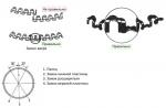
Rice. The appearance of a "wave" when the tire is rolling at a critical speed: 1 - tire; 2 - drum test bench
Critical tire rolling speed
When the rolling speed of a tire reaches a certain limit, the rolling power loss increases sharply. The rolling resistance coefficient is increased by about 10 times.
A "wave" appears on the surface of the tire's tread. This "wave", remaining motionless in space, moves along the tire carcass with the speed of its rotation.
The formation of a "wave" leads to the rapid destruction of the tire. In the tread-carcass area, the temperature rises sharply, as the internal friction in the tire becomes more intense, and the strength of the bond between the tread and the carcass decreases.
Under the action of centrifugal forces, which are significant in magnitude at high rolling speeds, there is a separation of tread sections or pattern elements.
The rolling speed at which the "wave" occurs is considered the critical rolling speed of the tyre.
As a rule, when rolling at a critical speed, the tire breaks down after a run of 5-15 km.
As tire pressure increases, the critical speed increases.
However, practice shows that during the SHKH the speed of motorcycles in some areas is 20-25% higher than the critical speed of the tires determined on the stand (when the tire rolls on the drum). In this case, the tires are not destroyed. This is explained by the fact that when rolling on a plane, the deformation of the tire is less (under the same mode) than when rolling on a drum, and, consequently, the critical speed is higher. In addition, the time the motorcycle is driven at a speed exceeding the critical speed of the tires is negligible. In this case, the tire is well cooled by the oncoming air flow. In this regard, the technical characteristics of sports motorcycle tires designed for GCS allow short-term overspeeding within certain limits.
Tire rolling under driving and brake wheel conditions. The rolling of the tire under the conditions of the driving wheel occurs when a torque Mkr is applied to the wheel.
The diagram of the forces acting on the drive wheel is shown in the figure.

Rice. Scheme of forces acting on the tire of the drive wheel during rolling
A torque Mcr is applied to a wheel loaded with a vertical force Q.
The reaction of the road Qp, equal in magnitude to the load Q, is displaced relative to the wheel axis by a certain distance a. The force Qp creates a rolling moment Ms:
Torque Mkr creates a traction sieve Rt:
Rt \u003d Mkr / Rk
where Rk is the rolling radius.
When the tire is rolling under the conditions of the driving wheel, under the action of a torque, the tangential forces in the contact are redistributed.
In the forward part of the contact in the direction of movement, the tangential forces increase, in the rear part they decrease. In this case, the resultant of the tangential forces X is equal to the traction force Pt.
The power expended on the rolling of the drive wheel is equal to the product of the torque Мcr and the angular velocity Wк of the wheel rotation:
This equation is valid only when there is no slippage in the contact.
However, the tangential forces cause the tread pattern elements to slip relative to the road.
Because of this, the actual value of the speed of the translational movement of the wheel Ud is somewhat lower than the theoretical Vt.
The ratio of the actual forward speed Vd to the theoretical Vt is called the wheel efficiency, which takes into account the loss of speed due to tire slippage relative to the road.
The amount of slippage a can be estimated using the following formula:
Obviously, the value of the actual speed Vd can vary from Vt to 0, i.e.:
The intensity of slippage depends on the magnitude of the tangential forces, which in turn are determined by the magnitude of the torque.
Previously shown:
Mcr = XRk;
X \u003d Pt \u003d Qv,
where v is the coefficient of adhesion of the tire to the road.
When the torque increases to a certain value exceeding the critical value, the value of the resultant tangential forces X becomes higher than the permissible value and the tire completely slips relative to the road.
Existing motorcycle tires in the operating load range can transmit torque of 55-75 kgf * m without full slip (depending on tire size, load, pressure, etc.).
When braking a motorcycle, the forces acting on the tire are similar in nature to the forces that occur when the tire is operating under the conditions of the drive wheel.
When braking torque Mt is applied to the wheel, the tangential forces are redistributed in the contact zone. The greatest tangential forces occur at the rear of the contact. The resultant of the tangential forces in magnitude and direction coincides with the braking force T:
With an increase in the braking torque Mt above a certain critical value, the braking force T becomes greater than the grip force of the tire with the road (T>Qv) and complete slippage begins in the contact, the skidding phenomenon occurs.
When braking to the skid in the contact zone, the temperature of the tread increases, the coefficient of adhesion drops, and the wear of the tread pattern increases sharply. Braking efficiency decreases (braking distance increases).
The most effective braking occurs at values of the braking force T, close in magnitude to the grip force of the tire with the road.
Therefore, when the driver uses the dynamic qualities of the motorcycle, in order to reduce tire wear, a torque must be supplied to the drive wheel, which ensures the least slip of the tire relative to the road.