ELECTRONIC CONTROL UNIT (CONTROLLER)
The ECU is located under the instrument panel and is the control center of the electronic engine management system.
It continuously processes information from various sensors and manages systems that affect exhaust emissions and vehicle performance.
The ECU receives the following information:
Position and frequency of rotation of the crankshaft;
Camshaft position;
Coolant temperature;
Intake air temperature and pressure;
Throttle position;
The presence of detonation in the engine;
vehicle speed;
Voltage in the vehicle's on-board network;
Request to turn on the air conditioner.
Based on the information received, the ECU controls the following systems and devices:
Fuel supply (injectors and electric fuel pump);
ignition system;
Idling regulator;
Adsorber of the gasoline vapor recovery system;
Fans of the engine cooling system;
Air conditioning compressor clutch;
Diagnostic system.
The ECU turns on the output circuits (injectors, various relays, etc.) by shorting them to ground through the output transistors of the controller. The only exception is the fuel pump relay circuit. The electric fuel pump is powered through a power relay. In turn, the relay winding is controlled by the ECU by closing one of the outputs to ground.
The ECU is equipped with a built-in diagnostic system. It can recognize ECM malfunctions by alerting the driver through the "Check engine" warning light. In addition, the ECU stores diagnostic codes that indicate the malfunction of a particular element of the system and the nature of this malfunction in order to assist specialists in diagnosing and repairing.
To exchange data with the computer, there is a diagnostic connector located next to the mounting block under the instrument panel.
A scanning device is connected to the diagnostic connector to read error information stored in the ECU memory, to check sensors and actuators in real time, to control actuators, and to reprogram the ECU.
The controller has the following types of memory:
Programmable Read Only Memory (PROM);
Random Access Memory (RAM);
Electrically reprogrammable memory (EPROM).
Programmable Read Only Memory (PROM). It contains a general program that contains a sequence of operating commands (control algorithms) and various calibration information. This information is management data
injection, ignition, idling, etc., which depend on the mass of the car, the type and power of the engine, transmission ratios and other factors.
PROM is also called a calibration memory. The contents of the PROM cannot be changed after programming.
This memory does not need power to save the information recorded in it, which is not erased when the power is turned off, i.e. this memory is non-volatile.
Random Access Memory (RAM). This is the "notebook" of the ECU. The microprocessor of the controller uses it to temporarily store measured parameters for calculations and intermediate information. The microprocessor can enter data into it or read them out as necessary. The RAM chip is mounted on the controller PCB. This memory is volatile and requires an uninterruptible power supply to maintain. When the power supply is interrupted, the diagnostic trouble codes and calculated data contained in the RAM are erased.
Electrically reprogrammable memory (EPROM). Used for temporary storage of codes- passwords of the car's anti-theft system (immobilizer). Codes- the passwords received by the ECU from the immobilizer control unit are compared with the codes stored in the EEPROM, as a result of which the engine start is allowed or prohibited. The EEPROM records vehicle operating parameters such as total vehicle mileage, total fuel consumption, and engine operating time.
ERPZU also registers some violations of the engine and car:
Operating time of the engine with overheating;
Engine operating time on low-octane fuel;
Engine operation time exceeding the maximum allowable speed;
Engine operation time with misfiring of the air-fuel mixture, the presence of which is indicated by the control lamp of the engine management system;
Engine operating time with a faulty knock sensor;
Engine operation time with a faulty oxygen concentration sensor;
Driving time of the car exceeding the maximum permitted speed during the break-in period;
Vehicle movement time with a faulty speed sensor;
The number of battery disconnections with the ignition switch on.
EEPROM is a non-volatile memory and can store information without powering the controller.
The controller is located on the left side of the air intake duct.
You will need a flat blade screwdriver to replace the ECU.
1. Disconnect a wire from the minus plug of the storage battery.
2. Using a screwdriver, remove the shield covering the controller.
3. Release the latch on the controller clamp...
4. ... and remove the bar.
5. Pull out the wire harness retainer.
6. Disconnect the block from the controller and remove the control unit from the air intake box.
7. Install the removed parts in the reverse order of removal.
ECU (electronic control unit) is a device that controls the parameters of mechanisms in the process of operation. Usually the abbreviation ECU is used in relation to the engine control unit.
In fact, the car also has brake system control units (ABS unit), a body control unit, which is often referred to as the Body Control Module (BCM or BSI), a climate control unit (climate control) and others.
Principle of operation
The principle of operation of the electronic engine control unit is based on a standard microcontroller architecture. Data on engine parameters from various sensors enter the ECU, then are processed (amplified, digitized, encoded).
The main processing of data according to a certain algorithm is performed by a microprocessor, which gives signals to the actuators via the output bus. These signals are adapted (converted from digital to analog, amplified) and fed to the connectors of the electronic control unit.
Among the tasks solved by the electronic engine control unit is the diagnosis of the operation of the main components. Modern ECUs can detect a variety of errors:
- lack of supply voltage on the electronic components of the engine or reduced power supply;
- breakage of electrical circuits or short circuit;
- incorrect signals at the output of sensors;
- misfiring and injection;
- mismatch of ignition angles;
- and many others.
Errors are stored in non-volatile memory until they are cleared using diagnostic devices (active errors cannot be deleted without eliminating the cause of the error).
In cars of earlier years of production, errors could be removed by temporarily (about 15 minutes) disconnecting the battery from the car's on-board network.
The ECU, together with the immobilizer, blocks the operation of the engine in case of unauthorized access. Each electronic engine control unit performs this function in accordance with the algorithm laid down by the manufacturer.
Can be blocked:
- ignition signal to the coil;
- fuel injection pulses;
- permission to start the starter, etc.
In some vehicles, the engine may start for a few seconds and stall.
Scheme
The circuit diagram of the engine control unit itself is a trade secret, and it is very problematic to find it even for domestic cars.
Therefore, ECU repairs are carried out only by high-level professional electronics engineers. Usually, injection and ignition control transistors, reference voltage stabilizers fail in control units, firmware flies.
Specialists sometimes specifically change the software firmware in order to increase engine response or reduce fuel consumption.
Video - ECU M74 firmware:
To repair the electronic components of the engine, an electrical circuit for connecting the computer is required. Such a scheme can be found in the manuals for the operation and repair of cars, software and hardware systems such as AUTODATA and TOLERANCE.
For example, consider the organization of the engine control circuit for a 2001 Volksvagen Golf 3 car, AEE engine, Magneti Marelli 1 AV control unit.
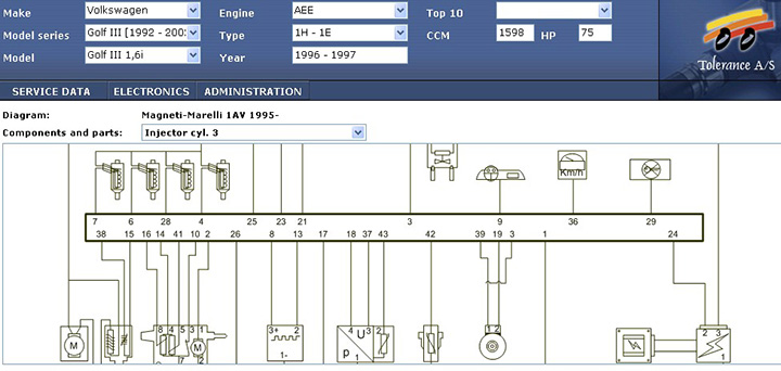
Without delving into the circuit, you can see that the ECU uses signals from the camshaft, mass air flow, coolant temperature, and oxygen sensors as sensors.
The signal coming from the camshaft sensor has the form:

As actuators, the ECU controls the signals for injection of injectors, throttle actuator, ignition to the coil switch:

The ECU is connected to the immobilizer, dashboard.
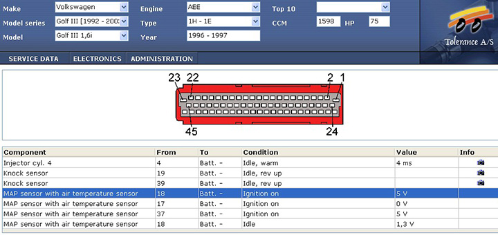
In order to check the electrical connections of the circuit nodes with the electronic engine control unit, you need to know the location of the contact pins (pinout), which is also given in the reference books:
Where is the engine control unit
In cars up to the 90s of production, the most rational location for the engine control unit was considered to be the space in the car interior near the left or right front pillar in the area of \u200b\u200bthe passenger or driver's legs. First of all, it was believed that these are the most protected places in terms of mechanical damage and moisture penetration.
Video - ECU transfer on Kalina:
Since the mid-90s, engine control units have been placed in the engine compartment. This is due to the following considerations:
- under the hood it is easier to troubleshoot electrical connections;
- all communications with engine sensors and actuators become shorter, therefore more reliable;
- ECUs have become more reliably protected from moisture with the help of special sealants.
In the absence of reference books, it is not difficult to find the electronic engine control unit by moving along the large wiring harness of the engine control system. It usually represents a small electronic unit in a metal casing with one or more connectors at the end.

In many cases, getting access to the internal space of the block to the electrical circuit is not easy: it is flooded with compounds that must be removed. The board usually contains a small number of components.

ECU symptoms
There is an opinion among auto electricians that the electronic engine management system fails last. Moreover, they can not always determine the malfunction of the engine control unit.
Indeed, the ECU can diagnose the nodes connected to it, but in most cases it cannot diagnose its own performance.
What can indicate a malfunction of the ECU?
The most common symptoms of a malfunction are the constant blown fuses serving the engine control unit. In practice, cases of polarity reversal of the battery connection are not uncommon. The ECU circuit has protective diodes for this case. If they break through, a short circuit occurs in the power supply, which leads to the constant blowing of the fuses. Faulty ones must be changed.
Also, a power failure can cause the battery to disconnect while the engine is running. In this case, the control unit is powered only from the generator and, if it is faulty, a situation may arise that the voltage is incorrectly applied to the unit.
It is impossible to remove the battery terminals with the engine running (!), as many motorists do when starting from someone else's battery.
How to check the ECU for performance
The first stage of the performance check is the control of all supply voltages.
The second stage is computer diagnostics. If the diagnostic device communicates with the engine, this is already a sign of the ECU's operability.
About blocking the block with an immobilizer, then you need to bind the keys.
In some cases, to determine the malfunction, it is necessary to disassemble the computer, that is, remove the sealant and remove the cover, gaining access to the board. It can detect burned-out conductive tracks, faulty transistors, diodes and other elements.
The most reliable way to check is to "throw" a known-good ECU. But it must be either non-immobilized or you will have to “tie up” the keys and the immobilizer again.
Sometimes a set of ECU + immobilizer + key chip is sold at disassembly. In this case, there are no problems. Connect the ECU and the immobilizer to the circuit, install the chip at the end of the pump coil on the ignition switch, and then start the engine.
Additional protection
For more confident protection of the engine control unit from battery polarity reversal, it is possible to install diodes in the supply circuits (better powerful zener diodes with a stabilization voltage of 15 - 17 Volts) in reverse connection.
Then overvoltage and polarity reversal will lead to the failure of the fuses serving the power supply circuits of the computer, increased voltage or reverse polarity voltage will not pass to the control unit, and this is the biggest danger.
In order to protect the computer from climatic influences, it is necessary to monitor the quality of the sealant. After five years of operation, it is advisable to take measures to improve tightness, since the old sealant may dry out at elevated temperatures under the hood.
Video - protection of the Renault Duster engine control unit (Logan, Largus):
You can not block access to the block with additional structures, put rags near it. This reduces the natural ventilation of the device, which heats up during operation of the vehicle.
Replacing the engine control unit
If the control unit is out of order and cannot be repaired, it should be replaced with a similar one with the same number indicated on the computer case.
Sometimes a slight deviation in the number is allowed. For example, a change in the last two or three digits may indicate a different engine size or modification, which may have little effect on technical characteristics.

The electronic control unit is one of the main components of the car, since it is, in fact, its “brains”. Thanks to this device, many different processes are carried out that ensure normal operation in general, but like any other device, the computer can fail. Read more about how to check the ECU for operability and in what cases it is necessary - read below.
[ Hide ]
Common ECU malfunctions and their causes
The electronic control system can fail for various reasons. One way or another, the car owner in this case will be faced with the need for diagnostics in order to accurately determine the malfunction of the unit, since in most cases these devices cannot be repaired. As practice shows, even specialists usually do not undertake to repair the device, but simply change it to a new one. But in any case, before you say goodbye to the computer, you need to carefully understand why it failed.

According to many electricians with whom we consulted when writing this material, the main reason for the failure of the unit is power surges in the on-board network. An overvoltage usually occurs as a result of a short circuit of one or more solenoids.
But this is only one of the most common reasons, in fact there are much more of them:
- Failure of the device can occur as a result of its mechanical damage. For example, it could be a strong blow or large vibrations, due to which a crack appeared on the module removal. Also, cracks and damage can form at the soldering points of elements or contacts.
- The ECM has overheated, this problem usually occurs as a result of temperature fluctuations. In practice, there are cases when, at low negative temperatures, drivers started engines at high speeds, trying to ensure accurate start of the power unit. At this point, overheating may have occurred.
- Impact on the ECM of corrosion. The formation of corrosion on the structure of the module may be due to changes in air humidity in the cabin, as well as the accumulation of condensate or moisture in the engine compartment of the vehicle.
- Violation of the sealing of the device. Such a problem will lead to the cause of the malfunction described above - in particular, the ingress of water into the module structure.
- If there is no connection with the computer, then such a malfunction could be caused by the intervention of outsiders in the control system, which could contribute to a violation of the integrity of the structure. For example, if they tried to “light up” another car from the car’s battery, while the engine of the first one was started, the terminals could also be disconnected with the battery when the engine was running. In addition, the problem could have arisen as a result of the fact that when connecting the battery, its polarity was reversed, that is, the terminals were connected incorrectly. In some cases, a malfunction may appear after turning on the starter unit to which the power bus was not connected.

In any case, for whatever reason the device fails, repair or replacement should be carried out after a complete diagnosis of the module has been completed. It must also be remembered that the nature of the breakdown may indicate possible malfunctions present in the operation of other systems. If these malfunctions are not corrected, this will lead to the fact that the new device will also fail.
If there is no connection with the ECU and the device refuses for some reason, the car owner may notice this by the following symptoms:
- The Check Engine icon does not light up on the dashboard, which appears when a malfunction is detected in the engine. Or, the icon may flash or take a while to appear. If the indicator blinks, you need to make sure that the problem is not in the light bulb itself, after that, check the unit itself.
- When you try to connect the ECU with your own hands to the scanner, it began to give out incorrect data that makes you doubt. That is, the information may be fundamentally different from the one that should be. If there is no connection with the computer, then the scanner may not recognize this device at all.
- The power unit of the car malfunctions, troit, may not start or start every other time, and it may even smoke. At the same time, there are no reasons for such behavior, including overheating.
- The ignition of the car began to work with passes.
- The engine cooling fan can turn on arbitrarily, without a command from the control unit.
- In the car, safety elements begin to fail, while they burn out repeatedly, but there are no visible reasons for this. If the fuses blow, this is usually due to an overvoltage in the on-board network or in a certain section of the electrical circuit, but the diagnostics do not detect power surges.
- From various sensors, pulses do not come or they come, but irregularly.
- In addition, another symptom may be incorrect operation of the gas pedal. When the driver presses the pedal, it may respond to pressing with a slowdown or very tight. This sign is the most true, especially if the pedal used to work in normal mode.
- Also, signs of damage may be visible on the body of the device. For example, these may be burnt out contacts or traces of burning on the wires.
- Another sign is the absence of control signals for the ignition system or fuel pump, idle speed controller and other devices controlled by the ECU (the author of the self-diagnosis video is Vladimir Chumakov).
How to independently diagnose the unit?
At first glance, it may seem that computer diagnostics is a difficult task that not everyone can handle. Indeed, it is not so easy to check your block, but having theoretical knowledge, it is quite possible to put them into practice.
Necessary tools and equipment
To check the functionality of the module yourself, you will need to perform a series of actions to connect to the computer.
To perform the test, you will need the following devices and items:
- Oscilloscope. It is clear that not every motorist has such a device, so if you do not have one, you can use a computer with the necessary diagnostic software pre-installed on it.
- Cable for connection to the device. You need to select an adapter that supports the KWP2000 protocol.
- Software. Finding diagnostic software today is not a problem. To do this, just monitor the network and find a program that is suitable for your vehicle. The program is selected taking into account the car, since different control units are installed on different machines.
Photo gallery “Getting ready for system diagnostics”
Action algorithm
The procedure for diagnosing the electronic control system is discussed below using the Bosch M 7.9.7 module as an example. This model of the control unit is one of the most common not only in domestic VAZ cars, but also in foreign-made cars. It should also be noted that the verification process is described using the KWP-D software as an example.
So, how to check the computer at home:
- First of all, the adapter used must be connected to a computer or laptop, as well as the ECM itself. To do this, connect one end of the cable to the output on the unit, and the other end to the USB output on the computer.
- Next, you need to turn the key in the car's ignition, but you do not need to start the engine. With the ignition on, you can run a diagnostic utility on the computer.
- After completing these steps, a window with a message should pop up on the computer screen, which confirms the successful start of troubleshooting in the controller. If for some reason the message does not appear, you need to make sure that the computer has successfully connected to the controller. Check the quality of the connection and connection of the cable with the unit and the laptop.
- Then, a table should be displayed on the laptop display, which will indicate the main technical characteristics and parameters of the vehicle.
- At the next stage, you need to pay attention to the DTC section (it may be called differently in different programs). This section will present all the malfunctions with which the power unit operates. All errors will be displayed on the screen as encrypted combinations of letters and numbers. To decrypt them, you need to go to another section, which is usually called Codes, or use the technical documentation for your car.
- In the event that there are no errors in this section, then you don’t have to worry now, since the vehicle’s engine is working fine (the author of the video at home is the AUTO REZ channel).
But this verification option is most relevant if the computer sees the block. If you have problems connecting to it, then you will need the electrical circuit of the device, as well as a multimeter. The tester or multimeter itself can be bought at any thematic store, and the ECM controller wiring diagram should be in the service manual. The scheme itself needs to be studied most carefully, this will be required for verification.
In the event that the ECM will point to a specific block, and not show erratic data, then, in accordance with the scheme, it must be found and called. If there is no exact information, then the only way out is to diagnose the entire system, as we said above, breakdowns are considered one of the main malfunctions.
After the breakdown is found, it is necessary to check the resistance and determine exactly where the cable is fixed. You will need to solder the corresponding new wire in parallel with the old one, if the cause lies in the breakdown, then these actions will correct the malfunction. In all other cases, only qualified specialists can solve the problem.
Video "Why the ECM does not communicate when checking"
From the video below, you can find out for what reasons there may be no communication between the ECM and a laptop during diagnostics (the author of the video is the Billye espada channel).
Unlike a carburetor, the injector (injectors) is not capable of dosing fuel on its own, therefore the operation of the injectors is regulated by an electronic engine control unit (ECU), which is often called a controller or an electronic engine control system (ECM). The ECU receives signals from a large number of various sensors and, using an algorithm sewn into memory, calculates the amount of fuel that will ensure optimal engine operation. In addition to controlling the injectors, the ECU determines the timing of the spark supply to each of the cylinders, replacing the ignition system of carbureted cars. Another extremely important function that the ECU performs is checking the condition of the engine.
How the ECU works
The most complete and efficient fuel burns only in a certain proportion with air. If there is more fuel than air (over-rich mixture), it does not burn completely, which leads to an increase in fuel consumption. In addition, unburned fuel residues form soot, which mixes with oil and settles on valves and piston rings, which reduces engine compression and shortens engine life. If there is less fuel than air (over-lean mixture), it does not burn smoothly, but explosively (detonation), as a result of which microcracks form in the piston, connecting rod and cylinder head (cylinder head).

At different operating modes of the engine, the optimal ratio of the air-fuel mixture must be changed. During hard acceleration or under heavy load, it is necessary to increase the amount of fuel (rich mixture) to avoid detonation and increase torque. When the engine is running at idle or low power, it is necessary to reduce the amount of fuel (lean mixture) to avoid incomplete combustion and excessive fuel consumption.
The ECU receives information from various sensors, due to which it determines the engine operating mode, speed and load on it. The mass air flow sensor (DMRV) supplies the input data needed to calculate the amount of fuel. After all, the required amount of fuel depends on the amount of air that got into the cylinders. The temperature sensor allows you to predict how the fuel will burn, because the rate of combustion of the air-fuel mixture in a cold and warm engine is different. shows what the driver expects from the motor. The more the gas pedal is pressed, the wider the throttle valve is open, the more air will enter the cylinders, which means that the crankshaft torque will increase.
A modern ECU calculates the amount of fuel not only for each engine stroke, but also separately for each cylinder. This allows you to make the engine the most stable and get the maximum ratio of fuel and power output. Having received information from all sensors, the ECU calculates the amount of fuel for each cylinder. Based on the signal from the crankshaft (DPKV) and camshaft (DPRV) position sensors, the ECU determines the time of fuel injection into each cylinder. Then the controller determines the time of creation of an ignition spark in each cylinder by the DPKV signal.
If the fuel burns too fast, the explosion determines . Having received a signal from DD, the controller slightly enriches the mixture and leaves a mark on this in memory. If knocking continues after the ECU has reached the maximum air-fuel mixture for this mode of engine operation, then the controller tries to eliminate knocking using a later ignition. When even this does not help, the ECU signals a “check engine” engine malfunction. Oxygen sensors (on the first injector Frets there were no such sensors, then they began to install one only in 2005 - 2007 they began to install two sensors) determine the efficiency of fuel combustion and the operation of the catalytic converter. If the amount of oxygen in the exhaust differs markedly from that programmed into the memory of the controller, then the ECU increases or decreases the fuel supply within a small range. If the adjustment range is not enough, the ECU gives an alarm and turns on the check engine indicator.
Differences between ECUs of different generations

ECUs of older models worked with a limited number of sensors, so they could not ensure the high-quality operation of the engine and the preparation of the air-fuel mixture. The lack of support for the phase sensor (DPRV) led to the fact that the controller did not determine which particular cylinder was working at the moment, so it injected fuel not into the combustion chamber, but into the air manifold. Devices operating in this mode were called central injection ECUs.
The installation of a phase sensor on the engine made it possible to clearly determine the order of operation of the cylinders, due to which the fuel was calculated separately for each combustion chamber. Devices operating in this mode were called distributed injection ECUs. ECUs have gotten better and better over time. Support for an oxygen sensor made it possible to more accurately regulate the combustion of fuel. Support for two oxygen sensors made it possible to switch to higher toxicity standards, because in this case it was possible to effectively use the catalytic converter. The appearance of each new ECU model brought with it new functions that reduce fuel consumption, increase engine power or life, and make driving more comfortable.
Engine control unit malfunctions
The controller is a complex electronic device, a microcomputer, therefore, a breakdown or malfunction of any element leads to a malfunction of the entire computer. In most cases, it is possible to determine the malfunction of the computer only by the elimination method, checking the operation of the entire injector. To learn how to do this, read the article "Diagnosis of the injector".
Causes of ECU malfunctions

On the first (VAZ 2108 - 21099) and second (VAZ 2113 - 2115) Samara families, the ECU is installed in a very unfortunate place, because there is a stove radiator next to it.
If the clamps are loose or the hose/radiator is leaking, then there is a high chance that coolant will enter the ECU, causing it to fail. If, for some reason, during engine operation, the contact between the battery and any terminal deteriorates, the computer supply voltage rises sharply and becomes unstable, which can lead to burnout of individual elements of the controller. Poor contact with candles or high resistance of high-voltage wires lead to the appearance of EMF (electromotive force) in the primary winding of the ignition coil, which can lead to a breakdown of the output transistors of the computer. Power surges often lead to damage to the "firmware" - the algorithm of actions recorded in the computer's memory. As a result, the motor starts to work incorrectly, but the “check engine” signal does not light up.
How to determine the state of the computer on VAZ cars
On VAZ 2108 - 2115 cars, the computer is located in the front right side of the passenger compartment, just below the glove box. To determine the state of the computer, as well as read the records (log) of errors in its memory, you need to connect to the diagnostic connector, which is installed in different places on different models. After all, the “check engine” signal informs about the presence of an engine malfunction, but does not tell which one. And the error code that is displayed on the dashboard of modern VAZ cars is not very informative.
Diagnostic connectors are located:
- on VAZ 2108 - 21099 with a low panel next to the computer, under the "glove compartment";
- on VAZ 2108 - 21099 with a high panel and 2113 - 2115 inside the center console;
- on VAZ 2108 - 2115 with an europanel on the panel next to the passenger door.

To determine the status of the computer and read the error log, you must connect a diagnostic scanner to the connector. Despite the fact that the cost of inexpensive scanner models is 2-4 thousand rubles, it is advisable to entrust this work to a specialist with professional equipment. After all, it is not enough to extract the error log from memory and decrypt it with the help of a reference book. It is necessary to establish what caused the engine to malfunction. Only an experienced diagnostician who is well versed in the repair of injection engines and fuel systems can correctly interpret the readings of the scanner.
Is it possible to install a different model of ECU on a car
Various ECU models are installed on VAZ 2108 - 2115 cars, which belong to the following families:
- January 4, put on the very first models of injection engines. They supported only a small number of sensors and provided fuel injection into a common air manifold;
- January 5 - 6 was installed on more modern cars. These ECUs provided injection into each cylinder separately, but did not support oxygen sensors;
- January 7 has been staged since 2007. These ECUs are not inferior to foreign counterparts and support all known sensors, due to which they control the engine more efficiently;
- Various GM models. These ECUs, depending on the class, type and cost, are similar to devices January 4 - 7;
- Various Bosch models. These ECUs, depending on the class, type and cost, are similar to devices January 4 - 7;
- Various Itelm models. These ECUs, depending on the class, type and cost, are similar to devices January 4 - 7.

Video - How to flash a Bosch 7.9.7+ ECU and interchangeability with January 7.2
Each model, even within a family or class, is only suitable for a certain combination of engine, sensors, wiring and firmware. Therefore, even different models within the same family should only be installed after consulting an injector specialist. Even if different ECU models turn out to be equipped with the same electrical connectors, a simple replacement will at best lead to poor engine performance.
All kinds of electronic devices are used in the control system of a modern car. They help in driving a vehicle, automating many processes, ensuring safety and improving other performance characteristics. To coordinate most processes, an electronic engine control unit is used.
In foreign-made cars, this node is called the ECU. A similar controller is installed with engines of various types, both with gasoline units and with diesel power plants. In the process of work, this node interacts with all kinds of sensors that capture current information about the current parameters of the car.
When determining the functionality of the engine ECU, what it is, and how it is involved in the processes, it is worth considering that the unit is processing the received parameters using the existing algorithm. Based on the available operating values of the motor, the ECU sends the appropriate commands to the actuators installed in the power unit.
In fact, the car is equipped with an on-board network. What is an ECU in a car? In fact, this is the main element of this network. Sometimes such electronics are not unreasonably called the main computer in a passenger car. A more slangy name is the word "brains".
Controllers are located not only in the internal combustion engine, but also in other systems of the machine. For example, they can be found in the following modules:
- gearbox "automatic";
- anti-lock braking system (ABS);
- airbag control;
- stability control systems (ESP, ESV, VSC, etc.);
- climate control unit, etc.
Each system has a personal management unit. They are all connected.
The main among the variety of electronics is the internal combustion engine control unit. Its tasks include continuous processing and exchange of current parameters with other systems. For interconnection, a special cable is used - the CAN bus. Thus, all elements are combined into a single digital system - the on-board network.
Thanks to the mutual two-way communication of all links included in the on-board network, optimization of the power plant operation is ensured.
When determining what an ECU is in a car where it is located, it must be taken into account that thanks to its operation it is possible to achieve the following comfortable indicators:
- fuel consumption is optimized;
- injection into the cylinders is timely regulated;
- during intake, a sufficient volume of air for the fuel mixture is automatically selected.
The performance of the main computer affects the power of the car, the torque value in different operating modes, as well as other important output characteristics. In such a situation, the module must always be operational.
Tasks assigned to the computer
Car manufacturers assign the following tasks to the control unit:
- ignition control;
- throttle position control;
- monitoring and adjustment of gas distribution phases;
- management and implementation of control functions over the phases of fuel injection;
- monitoring of the thermal state of the power plant and its cooling system;
- exhaust system control.

Information from sensors from the crankshaft about the frequency of its rotation is transmitted to the "brains". In this case, the current speed mode of the car, the voltage value of the entire control network, etc. are taken into account.
How it works and where is the engine control unit
The block is, in most cases, an electronic microcircuit densely loaded with elements. It is hidden under a plastic or metal case to protect it well from negative external influences. Quite often, the board is mounted in the engine compartment, closer to the center console. You can find out the actual location of the unit from the car manual.

The main elements of the head module are the microprocessor and memory blocks. Two or more output connectors are required for communication. They are easy to find on the outside for comfortable connection. One of them necessarily serves to interface with the vehicle's on-board network. Another one is diagnostic. It is through it that the connection with external scanning devices takes place.
There are several memory options on the main panel, allowing you to use all the features of this equipment. The permanent type of memory contains the main programs and algorithms for the current operation of the power plant. The entire software package is sewn in at the factory.
Separately, there is a module with RAM. With its help, the system manages to dynamically process the current information that comes from different sensors. At the same time, some results are saved for a short time. The following important parameters are stored in a separate memory module:
- the total time interval of operation of this engine;
- the total mileage traveled by the vehicle;
- the total amount of fuel consumed;
- codes of various accesses;
- error or lock codes.
Some data from such a module can be corrected, for example, the ECU error code is reset.
Electronic unit software
There are two types of software: control and functional. The first is monitoring pulses from sensors installed in different places. All accepted parameters must be within the acceptable ranges of values set by the manufacturer. If a drop out of a given segment by small values is detected, the device performance is updated.

The task of the functional module is to receive and process data. It also sends certain signals to the executive systems.
It is important to know that when control systems detect significant deviations from the established norms, the electronic unit is able to completely block the operation of the power plant.
In some cases, car owners seek to improve the performance of the computer or restore the software after some kind of failure. For such cases, a flashing of the electronics is carried out. In the course of work, standard software can be changed to third-party, corrected. This technique is called "chip tuning".
ECU error monitoring
The electronic unit provides a diagnostic system that provides a visual report to the car owner. When the controller detects a deviation, failure or some kind of error, the dashboard signals this with the corresponding light icon. Most often it is presented in yellow or red. This may be a pictogram with the designation "check-engine" (lit check).

The manufacturer can provide a corresponding personal numeric or alphabetic code for the error that has appeared. All such combinations are recorded in the memory of the electronic unit. There is a special place on the board for this. Connected special equipment in the form of a scanner helps to identify failures. You must use the appropriate cable and diagnostic connector.
The recorded parameters of deviations are read and their corresponding decoding takes place. At the same time, the system displays all the necessary information on the attached monitor. By studying the information received, it will be possible to clarify the current state of the vehicle.
Popular car electronic computer malfunctions
Traditionally, the ECU is a fairly reliable device in modern cars. However, depending on the quality of operation of the car or external factors, the system is capable of malfunctioning. Common reasons for the failure of such electronics are the following factors:
- significant heating of the device;
- a short circuit in the system;
- moisture penetration into the device case, connectors or bare areas;
- external mechanical damage to equipment;
- emerging corrosion processes.
Various characteristics help to indirectly identify malfunctions in the operation of electronics, for example, the motor fails with absolutely operable sensors and other systems of the power plant. Proper performance directly depends on the quality of the voltage in the entire on-board system of the car.
The failure of the car computer leads to unstable operation and failures in different ICE modes. Sometimes such an event is characterized by a complete blockage of the power plant. In this case, the "check" lights up on the instrument panel. It will not be possible to simply reset such an error, and if this happens, then the cause of the problem will not disappear, and the corresponding indicator will soon appear again.
In such a situation, it is necessary to diagnose the state of the computer. We recommend that you completely replace the failed board. It is believed that it is possible to carry out an independent repair of the microcircuit, which will cost less than installing a novelty. However, careful monitoring of performance and elimination of all possible malfunctions is required, which is not always available to motorists.


